EP0902442A1 - Spule mit induktivem und kapazitivem Verhalten - Google Patents
Spule mit induktivem und kapazitivem Verhalten Download PDFInfo
- Publication number
- EP0902442A1 EP0902442A1 EP97830451A EP97830451A EP0902442A1 EP 0902442 A1 EP0902442 A1 EP 0902442A1 EP 97830451 A EP97830451 A EP 97830451A EP 97830451 A EP97830451 A EP 97830451A EP 0902442 A1 EP0902442 A1 EP 0902442A1
- Authority
- EP
- European Patent Office
- Prior art keywords
- conductor
- coil
- terminal
- winding
- ignition
- Prior art date
- Legal status (The legal status is an assumption and is not a legal conclusion. Google has not performed a legal analysis and makes no representation as to the accuracy of the status listed.)
- Withdrawn
Links
Images

Classifications
-
- H—ELECTRICITY
- H01—ELECTRIC ELEMENTS
- H01F—MAGNETS; INDUCTANCES; TRANSFORMERS; SELECTION OF MATERIALS FOR THEIR MAGNETIC PROPERTIES
- H01F27/00—Details of transformers or inductances, in general
- H01F27/28—Coils; Windings; Conductive connections
- H01F27/2847—Sheets; Strips
-
- H—ELECTRICITY
- H01—ELECTRIC ELEMENTS
- H01F—MAGNETS; INDUCTANCES; TRANSFORMERS; SELECTION OF MATERIALS FOR THEIR MAGNETIC PROPERTIES
- H01F38/00—Adaptations of transformers or inductances for specific applications or functions
- H01F38/12—Ignition, e.g. for IC engines
-
- F—MECHANICAL ENGINEERING; LIGHTING; HEATING; WEAPONS; BLASTING
- F02—COMBUSTION ENGINES; HOT-GAS OR COMBUSTION-PRODUCT ENGINE PLANTS
- F02P—IGNITION, OTHER THAN COMPRESSION IGNITION, FOR INTERNAL-COMBUSTION ENGINES; TESTING OF IGNITION TIMING IN COMPRESSION-IGNITION ENGINES
- F02P3/00—Other installations
- F02P3/06—Other installations having capacitive energy storage
- F02P3/08—Layout of circuits
- F02P3/0876—Layout of circuits the storage capacitor being charged by means of an energy converter (DC-DC converter) or of an intermediate storage inductance
-
- H—ELECTRICITY
- H01—ELECTRIC ELEMENTS
- H01F—MAGNETS; INDUCTANCES; TRANSFORMERS; SELECTION OF MATERIALS FOR THEIR MAGNETIC PROPERTIES
- H01F27/00—Details of transformers or inductances, in general
- H01F27/28—Coils; Windings; Conductive connections
- H01F27/2847—Sheets; Strips
- H01F2027/2857—Coil formed from wound foil conductor
Definitions
- the present invention concerns an ignition coil for internal combustion engines with spark ignition as described in the preamble of Claim 1 hereinbelow.
- an ignition coil consist of two electrical windings, respectively a primary winding and a secondary winding, both formed around a ferromagnetic core or a part thereof.
- the two windings are magnetically interlinked, but electrically insulated from each other, and make it possible to transform a low voltage (just a few volts in inductive type-systems, or a few hundreds of volts in capacitor-discharge systems) applied to the ends of the primary winding into a high voltage (several tens of kilovolts) at the ends of the secondary winding.
- ignition systems traditionally comprise a low-voltage generator, usually the battery of the motor vehicle, one or more ignition coils connected to the spark plugs assembled in the cylinder head, to which the said coils furnish the high voltage in order to produce the spark, and an electronic control circuit to set the ignition times and modes.
- the technically most valid ignition systems, and also the ones most widely used today, are the inductive-type system and the capacitor-discharge one, the two types being distinguished by the different solutions they adopt for storing the energy and transferring it from the battery to the spark plug.
- the low-voltage battery normally 12 volt in the case of motor vehicles
- the coil to its primary winding
- the coil will generate a magnetic field.
- the coil is thus used at first as a device for storing energy in the magnetic field generated by the primary winding and subsequently as a transformer in order to obtain the required high voltage at the ends of the secondary winding by transferring therein the stored energy.
- the low-voltage battery is generally followed by a voltage up-transformer and connected to a capacitor, which is charged by the direct current provided by the battery in order to store the energy needed for ignition in its own electric field.
- the coil operates exclusively as a transformer, converting the voltage that the capacitor discharges to the primary winding at the proper time into the high voltage required in the secondary one.
- Both ignition systems therefore have the common feature of using coils as transformers in order to make possible the transmission of energy from a charge phase in which an external battery (or, more generically, an external driving circuit) supplies the energy that is accumulated in the magnetic or electric field by, respectively, the primary winding or the capacitor, to a subsequent discharge phase in which said energy, transferred to the secondary winding, will permit a spark to pass between the electrodes of the spark plug.
- an external battery or, more generically, an external driving circuit
- the object of the present invention is therefore that of ensuring interchangeability of the two ignition systems by proposing a coil that can be used as an energy accumulator and as a transformer in both the described ignition systems, at the same time reducing also the overall costs by eliminating the need for a discrete capacitor.
- this object is attained by means of an ignition coil in accordance with the characterizing part of Claim 1 hereinunder.
- This coil in accordance with the invention is realized in such a manner as to include in itself also the function of the capacitor as alternative to the use of the discrete component.
- Two electrically insulated conductors for example two armatures facing each other and separated by a dielectric medium, are wound around the magnetic core to form the primary winding, displaying at the same time inductive behaviour (each of the wound conductors has its own resistance and inductance) and capacitive behaviour (between the two insulated conductors).
- These conductors of the primary winding provide a plurality of terminals and the choice of which terminals are to be connected to the other parts of the system (especially the electronic control circuit) completely defines the properties and the behaviour of the system.
- FIGS 1 and 2 illustrate the circuit diagrams for the two ignition systems recalled in the introductive part of the present description.
- the following brief analysis is intended to highlight the individual components of such systems and their function, as well as their connections to the ignition coil, and convey a proper understanding of the manner in which the system functions in both the charge and the discharge phase.
- the circuit diagram shown is that of an ignition system of the inductive type that employs a separate coil assembled with each corresponding spark plug; more particularly, this figure illustrates a part of the complete system regarding a single spark plug 10 and its associated ignition coil 12.
- the stable (apart from such variations as may be due to the state of charge of the battery or the operating temperature) supply voltage V BATT is connected directly to the terminal A of the primary winding 21 of the coil 12.
- the terminal B at the other end of the winding is connected to the collector of a transistor Q1, the emitter of which is connected to ground via a resistor R1, while its base receives the control signal 40 coming from an electronic control unit (ECU) 42.
- ECU electronice control unit
- the ECU 42 commands the switch Q1 to close, thus opening a direct path to ground for the steady current flowing in the primary winding 21; the flow of this current generates a magnetic flux.
- the ECU 42 commands the opening of the switch Q1 (discharge phase)
- the current flowing in the primary winding becomes suddenly interrupted and the coil acts as a transformer, thus causing the energy stored in the magnetic field to be transferred to the secondary winding 22 and, consequently, producing also a voltage peak (several tens of kilovolts) at the electrodes of the spark plug 10.
- FIG. 2 it is shown the circuit diagram of an ignition system of the capacitor-discharge type, always regarding to a solution using a separate coil assembled with each corresponding spark plug; more particularly, this figure illustrates a part of the complete system regarding a single spark plug 10 and its associated ignition coil 12.
- the stable (apart from such variations as may be due to the state of charge of the battery or the operating temperature) supply voltage V BATT is converted into a voltage of the order of several hundred volts by a transformer 44, while the current, via a safety diode D1 , charges a capacitor C1 of predetermined capacity.
- An armature of the capacitor C1 is connected directly to the terminal A of the primary 21 winding of the coil 12, while the second armature, whose terminal corresponding to the anode of the diode D1 we shall designate by C, is connected to the other terminal B of the primary winding 21 (connected to ground) via a controlled diode or thyristor D2.
- the said thyristor D2 is controlled by a control unit (ECU) 42.
- ECU control unit
- the capacitor C1 is in parallel with the primary winding 21, and the terminal C coincides with the grounded terminal B.
- the energy accumulated in the capacitor electric field is transferred to the primary winding of the coil, and the voltage which establishes between the ends A and B of the said primary winding is transformed into a voltage of several tens of kilovolts across the terminals of the secondary winding 22 and therefore also across the terminals of the spark plug 10.
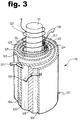
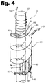
- the coil 112 according to the invention illustrated by these drawings is of the "cigar-shaped" type, i.e., it has a magnetic core 120 of cylindrical shape and a primary winding 121 and a secondary winding 122 that are both coaxial with it.
- a coil of the "cigar-shaped" type is described, for example, in the European patent application No. EP-97 830 306.3 by the same applicant.
- the principal characteristics of the invention do not depend on the particular coil model taken into consideration and can apply also to other structures known in the technical field.
- the primary winding 121 consists of two electrically insulated metallic armatures 123 and 124 that face each other and are separated by an insulating dielectric 125. These two armatures have the form of a ribbon and are wound coaxially with the magnetic core 120 to form a multiplicity of electric turns in accordance with two possible winding patterns.
- the ribbon is wound as a cylindrical spiral surrounding the magnetic core 120 and the secondary winding 122.
- An additional layer 126 of insulating dielectric is used to separate the armatures of the various concentric turns that come to face each other.
- the ribbon is wound in the manner of a helix coaxial with the core 120.
- a second layer 126 of insulating dielectric is used to insulate the armatures of the primary winding as much as possible from the conductor of the secondary winding, which is likewise coaxial with the core and wound inside the primary winding.
- each wound armature 123 or 124 behaves like a series of turns carrying a current and therefore constitutes an inductor in the truest sense of the term. At one and the same time an electric capacity comes into being between these selfsame facing armatures separated by the dielectric 125, so that the said armatures will also form the equivalent of a capacitor.
- Appropriate terminals are attached to the armatures 123 and 124, thus making it possible for the whole of the primary winding 121 to be connected to the external electronic circuits.
- a first terminal 131 and a second terminal 132 are attached to the armature 123 , at the two ends of the winding, and inductive behaviour can therefore be recognized between these terminals.
- a third terminal 133 is attached to the armature 124 at the particular end of the winding that is more readily accessible; a capacitive behaviour becomes established between this terminal and a terminal of the other winding.
- the physical terminal 131 corresponds to the electric terminal designated in the circuit diagrams by the letter A
- the physical terminal 132 coresponds to the electric terminal B
- the physical terminal 133 corresponds to the electric terminal C.
- only two of these terminals are used to connect the coil to the external electronic circuits.
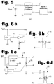
- FIG 5 shows a generalized circuit diagram of an entire ignition system - irrespective of whether it is of the inductive or the capacitor-discharge type - that includes the driving and control module 50 and the ignition coil in accordance with the invention 112. These two blocks are described in greater detail in Figures 6a and 6d.
- the driving and control module 50 is made up as shown by the circuit diagram of Figure 6a (derived directly from the circuit of Figure 1) and is connected to the terminals A and B of the electrical equivalent of the coil 112 illustrated by Figure 6b.
- the terminal 133 (C) of the primary winding is left free, so that the armature 124 does not play any part at all and the armature 123 alone behaves like an ordinary inductor magnetically coupled with the secondary winding 122.
- the driving and control module 50 is made up as shown by the circuit diagram of Figure 6c (derived directly from the circuit of Figure 2) and is connected to the terminals C and B of the electric equivalent of the coil 112 illustrated by Figure 6d.
- the terminal 131 (A) is left free, with the result that the capacitance between the two armatures and the inductance provided by the armature 123 wound around the core will be connected in series between the other two terminals.
- one and the same coil can be used with the two distinct circuit layouts of the driving and control module 50 by simply choosing the appropriate terminals according to the type of ignition system it is proposed to realize. Nor is it to be excluded that in some future application even the driving and control module 50 could be reduced to some common layout valid for both alternatives, thus rendering possible complete interchangeability between the two described ignition systems.
Landscapes
- Engineering & Computer Science (AREA)
- Power Engineering (AREA)
- Ignition Installations For Internal Combustion Engines (AREA)
Priority Applications (1)
| Application Number | Priority Date | Filing Date | Title |
|---|---|---|---|
| EP97830451A EP0902442A1 (de) | 1997-09-15 | 1997-09-15 | Spule mit induktivem und kapazitivem Verhalten |
Applications Claiming Priority (1)
| Application Number | Priority Date | Filing Date | Title |
|---|---|---|---|
| EP97830451A EP0902442A1 (de) | 1997-09-15 | 1997-09-15 | Spule mit induktivem und kapazitivem Verhalten |
Publications (1)
| Publication Number | Publication Date |
|---|---|
| EP0902442A1 true EP0902442A1 (de) | 1999-03-17 |
Family
ID=8230771
Family Applications (1)
| Application Number | Title | Priority Date | Filing Date |
|---|---|---|---|
| EP97830451A Withdrawn EP0902442A1 (de) | 1997-09-15 | 1997-09-15 | Spule mit induktivem und kapazitivem Verhalten |
Country Status (1)
| Country | Link |
|---|---|
| EP (1) | EP0902442A1 (de) |
Cited By (3)
| Publication number | Priority date | Publication date | Assignee | Title |
|---|---|---|---|---|
| WO2015119916A1 (en) * | 2014-02-04 | 2015-08-13 | Michael Hopkins | Reservoir recovery energy flux coupling cell, unit, systems, and method |
| US20240038497A1 (en) * | 2022-07-29 | 2024-02-01 | COMET Technologies USA, Inc. | Compound helical inductor coil |
| CN119093761A (zh) * | 2024-11-05 | 2024-12-06 | 益能电焰科技(深圳)有限公司 | 一种升压电路模块和电焰灶 |
Citations (5)
| Publication number | Priority date | Publication date | Assignee | Title |
|---|---|---|---|---|
| GB982561A (en) * | 1960-04-06 | 1965-02-10 | Ass Elect Ind | Improvements in and relating to helically wound coils |
| GB2137427A (en) * | 1983-03-28 | 1984-10-03 | Mcculloch Corp | Electrical energy storage and transfer devices |
| WO1989005035A1 (en) * | 1987-11-18 | 1989-06-01 | Ducati Energia S.P.A. | Wound capacitor device with controlled impedance |
| WO1989010622A1 (en) * | 1988-04-18 | 1989-11-02 | Ducati Energia S.P.A. | Improved capacitor with controlled impedance |
| EP0742369A1 (de) * | 1995-05-12 | 1996-11-13 | MAGNETI MARELLI S.p.A. | Auslöscheschaltung für Zündvorrichtung |
-
1997
- 1997-09-15 EP EP97830451A patent/EP0902442A1/de not_active Withdrawn
Patent Citations (5)
| Publication number | Priority date | Publication date | Assignee | Title |
|---|---|---|---|---|
| GB982561A (en) * | 1960-04-06 | 1965-02-10 | Ass Elect Ind | Improvements in and relating to helically wound coils |
| GB2137427A (en) * | 1983-03-28 | 1984-10-03 | Mcculloch Corp | Electrical energy storage and transfer devices |
| WO1989005035A1 (en) * | 1987-11-18 | 1989-06-01 | Ducati Energia S.P.A. | Wound capacitor device with controlled impedance |
| WO1989010622A1 (en) * | 1988-04-18 | 1989-11-02 | Ducati Energia S.P.A. | Improved capacitor with controlled impedance |
| EP0742369A1 (de) * | 1995-05-12 | 1996-11-13 | MAGNETI MARELLI S.p.A. | Auslöscheschaltung für Zündvorrichtung |
Cited By (6)
| Publication number | Priority date | Publication date | Assignee | Title |
|---|---|---|---|---|
| WO2015119916A1 (en) * | 2014-02-04 | 2015-08-13 | Michael Hopkins | Reservoir recovery energy flux coupling cell, unit, systems, and method |
| US20190237998A1 (en) * | 2014-02-04 | 2019-08-01 | Michael Hopkins | Reservoir recovery energy flux coupling cell, unit, systems, and method |
| US10666089B2 (en) * | 2014-02-04 | 2020-05-26 | Michael Hopkins | Reservoir recovery energy flux coupling cell, unit, systems, and method |
| US20240038497A1 (en) * | 2022-07-29 | 2024-02-01 | COMET Technologies USA, Inc. | Compound helical inductor coil |
| US12646686B2 (en) * | 2022-07-29 | 2026-06-02 | COMET Technologies USA, Inc. | Compound helical inductor coil |
| CN119093761A (zh) * | 2024-11-05 | 2024-12-06 | 益能电焰科技(深圳)有限公司 | 一种升压电路模块和电焰灶 |
Similar Documents
| Publication | Publication Date | Title |
|---|---|---|
| US5947093A (en) | Hybrid ignition with stress-balanced coils | |
| EP0387993B1 (de) | Zündanordnung für Brennkraftmaschine mit einem Primärwicklungsmodul | |
| JP2002502106A (ja) | 高パルス速度発火源 | |
| US4561707A (en) | Current-sheet inductor network and pulse-forming systems | |
| CN101517668B (zh) | 用于能量储存和能量转换的装置 | |
| US6215385B1 (en) | Ignition coil with primary winding outside of secondary winding | |
| EP0156917B1 (de) | Hochenergetische zündvorrichtung | |
| EP0224452A1 (de) | Zündsystem für Brennkraftmaschine | |
| US7178513B2 (en) | MCU based high energy ignition | |
| WO2003089784A2 (en) | Improved mcu based high energy ignition | |
| EP3104379B1 (de) | Funkenzündungstransformator für nichtlinearen sekundärstrom | |
| US5093770A (en) | Electrical energy storage system | |
| US6422225B1 (en) | Ignition coil and method of making | |
| US6292082B1 (en) | Ignition device for an internal combustion engine | |
| JP2002039042A (ja) | 内燃機関用点火コイル装置 | |
| US6222435B1 (en) | Stick coil for igntion systems | |
| EP0742369A1 (de) | Auslöscheschaltung für Zündvorrichtung | |
| US5156136A (en) | Ignition coil | |
| JP2997577B2 (ja) | 内燃機関用点火コイル | |
| EP0893599A1 (de) | Zündspule mit offenem Kern und zentralem Luftspalt | |
| US20010019297A1 (en) | Rod ignition transformer for internal-combustion engines | |
| JP2001257085A (ja) | 放電灯起動装置 | |
| JPH1074643A (ja) | 高圧放電灯点灯装置の高電圧発生コイル | |
| RU2285307C2 (ru) | Катушка зажигания для двигателя внутреннего сгорания (варианты) | |
| JP2002260938A (ja) | 内燃機関用点火コイル |
Legal Events
| Date | Code | Title | Description |
|---|---|---|---|
| PUAI | Public reference made under article 153(3) epc to a published international application that has entered the european phase |
Free format text: ORIGINAL CODE: 0009012 |
|
| AK | Designated contracting states |
Kind code of ref document: A1 Designated state(s): AT BE CH DE DK ES FI FR GB GR IE IT LI LU MC NL PT SE |
|
| AX | Request for extension of the european patent |
Free format text: AL;LT;LV;RO;SI |
|
| AKX | Designation fees paid | ||
| STAA | Information on the status of an ep patent application or granted ep patent |
Free format text: STATUS: THE APPLICATION IS DEEMED TO BE WITHDRAWN |
|
| 18D | Application deemed to be withdrawn |
Effective date: 19991001 |