EP0902444A1 - Appareils pour le traitement magnétique de media liquides ou gazeux et applications utilisant ceux-ci - Google Patents
Appareils pour le traitement magnétique de media liquides ou gazeux et applications utilisant ceux-ci Download PDFInfo
- Publication number
- EP0902444A1 EP0902444A1 EP98115708A EP98115708A EP0902444A1 EP 0902444 A1 EP0902444 A1 EP 0902444A1 EP 98115708 A EP98115708 A EP 98115708A EP 98115708 A EP98115708 A EP 98115708A EP 0902444 A1 EP0902444 A1 EP 0902444A1
- Authority
- EP
- European Patent Office
- Prior art keywords
- arrangement according
- magnetic
- ionization
- pole
- modules
- Prior art date
- Legal status (The legal status is an assumption and is not a legal conclusion. Google has not performed a legal analysis and makes no representation as to the accuracy of the status listed.)
- Withdrawn
Links
Images



Classifications
-
- C—CHEMISTRY; METALLURGY
- C02—TREATMENT OF WATER, WASTE WATER, SEWAGE, OR SLUDGE
- C02F—TREATMENT OF WATER, WASTE WATER, SEWAGE, OR SLUDGE
- C02F1/00—Treatment of water, waste water, or sewage
- C02F1/48—Treatment of water, waste water, or sewage with magnetic or electric fields
- C02F1/481—Treatment of water, waste water, or sewage with magnetic or electric fields using permanent magnets
- C02F1/482—Treatment of water, waste water, or sewage with magnetic or electric fields using permanent magnets located on the outer wall of the treatment device, i.e. not in contact with the liquid to be treated, e.g. detachable
-
- B—PERFORMING OPERATIONS; TRANSPORTING
- B01—PHYSICAL OR CHEMICAL PROCESSES OR APPARATUS IN GENERAL
- B01J—CHEMICAL OR PHYSICAL PROCESSES, e.g. CATALYSIS OR COLLOID CHEMISTRY; THEIR RELEVANT APPARATUS
- B01J19/00—Chemical, physical or physico-chemical processes in general; Their relevant apparatus
- B01J19/08—Processes employing the direct application of electric or wave energy, or particle radiation; Apparatus therefor
- B01J19/087—Processes employing the direct application of electric or wave energy, or particle radiation; Apparatus therefor employing electric or magnetic energy
-
- F—MECHANICAL ENGINEERING; LIGHTING; HEATING; WEAPONS; BLASTING
- F02—COMBUSTION ENGINES; HOT-GAS OR COMBUSTION-PRODUCT ENGINE PLANTS
- F02M—SUPPLYING COMBUSTION ENGINES IN GENERAL WITH COMBUSTIBLE MIXTURES OR CONSTITUENTS THEREOF
- F02M27/00—Apparatus for treating combustion-air, fuel, or fuel-air mixture, by catalysts, electric means, magnetism, rays, sound waves, or the like
- F02M27/04—Apparatus for treating combustion-air, fuel, or fuel-air mixture, by catalysts, electric means, magnetism, rays, sound waves, or the like by electric means, ionisation, polarisation or magnetism
- F02M27/045—Apparatus for treating combustion-air, fuel, or fuel-air mixture, by catalysts, electric means, magnetism, rays, sound waves, or the like by electric means, ionisation, polarisation or magnetism by permanent magnets
-
- F—MECHANICAL ENGINEERING; LIGHTING; HEATING; WEAPONS; BLASTING
- F23—COMBUSTION APPARATUS; COMBUSTION PROCESSES
- F23K—FEEDING FUEL TO COMBUSTION APPARATUS
- F23K5/00—Feeding or distributing other fuel to combustion apparatus
- F23K5/02—Liquid fuel
- F23K5/08—Preparation of fuel
-
- H—ELECTRICITY
- H01—ELECTRIC ELEMENTS
- H01F—MAGNETS; INDUCTANCES; TRANSFORMERS; SELECTION OF MATERIALS FOR THEIR MAGNETIC PROPERTIES
- H01F7/00—Magnets
- H01F7/02—Permanent magnets [PM]
- H01F7/0273—Magnetic circuits with PM for magnetic field generation
- H01F7/0278—Magnetic circuits with PM for magnetic field generation for generating uniform fields, focusing, deflecting electrically charged particles
-
- B—PERFORMING OPERATIONS; TRANSPORTING
- B01—PHYSICAL OR CHEMICAL PROCESSES OR APPARATUS IN GENERAL
- B01J—CHEMICAL OR PHYSICAL PROCESSES, e.g. CATALYSIS OR COLLOID CHEMISTRY; THEIR RELEVANT APPARATUS
- B01J2219/00—Chemical, physical or physico-chemical processes in general; Their relevant apparatus
- B01J2219/08—Processes employing the direct application of electric or wave energy, or particle radiation; Apparatus therefor
- B01J2219/0803—Processes employing the direct application of electric or wave energy, or particle radiation; Apparatus therefor employing electric or magnetic energy
- B01J2219/085—Processes employing the direct application of electric or wave energy, or particle radiation; Apparatus therefor employing electric or magnetic energy creating magnetic fields
- B01J2219/0852—Processes employing the direct application of electric or wave energy, or particle radiation; Apparatus therefor employing electric or magnetic energy creating magnetic fields employing permanent magnets
Definitions
- the invention first relates to an arrangement for magnetic Ionization of liquid or gaseous media.
- a hydrocarbon Fuel thought. It is known to do this with either Magnetic fields generated electromagnetically or by iron magnets in a liquid fuel line build up permanent magnetic field and thus the fuel magnetically ionize. This changes the orientation of the hydrocarbon molecules in the fuel.
- ionization also called ionization Ions by separation and / or attachment of one or more Electrons formed on a neutral atom or molecule. In the case of separation, the ion formed is one or several times positively charged, in the case of attachment one or multiple negative, depending on whether one or more than one electron was separated or attached.
- the ionization occurs due to the field ionization, in which strong inhomogeneous Fields bound in an electrical / magnetic way Detach electrons from their binding potential.
- the separation of ions turns the hydrocarbon molecules positively charged to the inherently negative to be able to draw charged oxygen with less energy.
- brackets are, like the later versions show practical handling, require little space and create an optimal and constantly in one direction going, attracting magnetization of the wire cross-section and thus the medium flowing in it. This attractive On the one hand, magnetic field results in a correspondingly strong ionization. It also creates a certain attraction between the two brackets in the operating position reached. This attraction is then significantly increased if the pipeline is made of steel. It is a Another advantage of the invention that even with a pipe the magnetic force generated inside the tube is strong is enough, despite that given by the pipe wall Shielding a sufficiently large magnetic flux density in the Build up pipe cross-section.
- the use is also essential of rare earth magnets or equivalent magnetic materials. They have a much higher level than iron magnetic flux density, e.g.
- Claim 2 which is still perfected according to claim 3 can be both for an advantageous attachment and Holder of the permanent magnets as well as for a magnetic one Shielded to the outside.
- This shield prevents that lines of magnetic force move outwards.
- a Main field of application of the invention is the ionization of Fuels for motor vehicles and this is the arrangement according to the invention on the supply lines of the fuel has to be attached, namely would have to appear externally Magnetic lines of force the result that they in the motor vehicle, especially in the engine compartment, in many forms Disrupt electronics or even render them unusable.
- the Magnets in their direction and thus in the main direction of the magnetic field formed by them positioned so that over the wire cross-section an almost uniform magnetic field is created. This can be structurally-constructive in simple Completed by the features of claim 5 become.
- the invention can be used in various ways or applicable.
- it is liquid or gaseous Fuels and thereby fuels of an internal combustion engine thought (see claim 10).
- claim 13 is also the use for magnetic ionization of the fuel a heating conceivable, and according to claim 16 of Gases of a gas heater.
- Claim 20 contains advantageous in the practice of the invention Materials for the permanent magnets used.
- Claim 18 is an arrangement according to claim 17 on Hot water outlet of a water heater, e.g. a boiler, intended. It is particularly important to a central Domestic hot water heater thought, its hot water outlet over longer lines to the individual tapping points of a building is fed. In particular heated, calcareous This is because water tends to become blocked when pipes flow through it to start on their inner walls.
- the invention also relates to claims 21 to 23 with a reinforcement of the pole pieces, which are attached to the outside of the permanent magnets. This has a corresponding reinforcement of the above explained magnetic shield to the outside result. This can occur both when ionizing calcareous water as well as in the ionization of hydrocarbonaceous Fuel can be used successfully.
- Fig. 1 shows in cross section the structure of a holder the invention between a lower housing part 1 and a upper housing part 2, the edges 3 with each other are connected.
- These permanent magnets are made of a rare earth magnet material, e.g. Neodymium-iron-boron alloy (NdFeB) or samarium cobalt.
- the length of the magnet 5 is the dash-dotted representation in Fig. 3 can be seen. They extend essentially over the entire length the length L of the bracket.
- the pole piece 4 is close according to this embodiment its central longitudinal line 6 angled at points 7, so that on the surfaces created by these bends 8th the permanent magnets 5 attached and with their magnetic Longitudinal axis 9 are aligned so that after Attaching the bracket to a medium leading Pipeline these longitudinal axes 9 approximately in the central longitudinal axis 10 meet the pipe 11 and a corresponding one Form an angle with each other (see Fig. 4). Because mounts with given dimensions on lines 11 different Diameter must be attached, the above Meeting the magnetic longitudinal axes 9 exactly in the central longitudinal axis 10 the pipeline only with a suitable outer diameter the pipe 11 may be the case. Nevertheless, the Magnet lines 13 indicated in FIG.
- FIG. 4 there are two modules on the pipeline attached to opposite sides and a "north" module A in FIG. 4 above and a “south” module B in Fig. 4 below, which the permanent magnets 5 with the desired magnetic polarity and the already explained hold advantageous position on the pipe 11.
- the permanent magnets 5 With the desired magnetic polarity and the already explained hold advantageous position on the pipe 11.
- the result is a rectified and attractive permanent magnetic Field through the line cross section 12 with the desired consequence of magnetic ionization of the Medium. It is essential that magnetization always in the same direction. This is through the Positioning of the magnets 5 reached, the magnets 5 of the upper module A in FIG. 4 with its N poles to the pipeline are directed while the magnets 5 of the in Fig. 4 lower modules B with their S poles to the pipeline 11 are aligned.
- Magnetic field lines 13 magnetic field lines from the in 4 top left N-pole (module A) that in Fig. 4th lower right S pole (module B), as well as from the in Fig. 4 top right N pole to the left in Fig. 4 S pole below.
- Number 13 ' also magnetic field lines from the top right located N pole to the S pole located on the lower right, as well from the top left N pole to the bottom left S pole.
- This is an almost complete enforcement of cross section 12 with magnetic field lines 13, 13 '.
- the presence of an attractive magnetic field an almost straight course of the magnetic field lines between the N poles and the S poles (see Fig. 4).
- the aforementioned, together forming the magnetic field 13, 13 ' N and S poles are roughly at the corners of a rectangle or squares. It also creates an attractive magnetic field built up.
- the two modules or brackets A, B have, as well 4 shows, preferably the same sizes and dimensions, but where the strength of the magnetic force by the above choice the length of the magnets adapted to the respective requirements can be.
- the lower housing part 1 in FIG. 1 the 4 intended for contact with the respective pipeline, angled so concavely that both angles about parallel to the angled regions 8 of the pole shoes 4 run.
- the each pole piece 4 attached magnets 5 with their respective pole exit surfaces practically on the lower Fit housing part 1. This results in the operating situation the desired alignment of the longitudinal central axis 9 the magnets (see Fig. 4).
- the pole shoes 4 are of such a steel plate Thickness, e.g. 5 mm, designed to be the permanent magnet 5 shield magnetically from the outside.
- the pole pieces are either clamped between the two housing parts 1, 2 or with at least one of the housing parts by gluing connected.
- a preferred embodiment of an adhesive bond consists in inserting an appropriate amount of silicone. This can be done according to paragraph 16 between the top Housing part 2 and the pole piece 4, and by a silicone compound 17 between the lower housing part 1 and the pole piece 4 happen.
- the two housing parts 1, 2 are made of plastic.
- the two brackets separate modules, which either by the magnetic force after placing on the line 11 from hold on to it yourself.
- the drawing cannot Cable ties shown are provided, which by lateral, eyelet-like slots 14 of the lower housing part 1 inserted and around the two in the operating position (Fig. 4) existing brackets looped around and strapped become.
- the cable ties are placed in the corresponding ones Recesses 18 in the edge of the upper part 2.
- the lower housing part 1 can have a center over its Have longitudinally extending web 19, the to serves to stiffen it.
- the two brackets on one of their long sides can connect with each other like a hinge and thereby in one To maintain distance, which is approximately their distance according to FIG. 4 corresponds (not shown in the drawing).
- FIG. 5 shows that one of the Contact surface 1 'of each lower housing part 1 a Strip 15 of a preferably elastically compressible Material, e.g. a plastic foam, can stick. This is useful if you have one in diameter much smaller pipe than shown in Fig. 4 equip with the same brackets and thereby about The course of the magnetic longitudinal axes 9 according to FIG. 4 likewise wants to achieve.
- a preferably elastically compressible Material e.g. a plastic foam
- these modules between the fuel filter and Arrange carburetor / injection pump. This could also be the case between the injection pump and the injector.
- A is another area of application of the invention the fuel supply in a heating system.
- the magnetic ionization takes place before the oil filter, if an oil heater is provided. It would be one too Oil heating the magnetic ionization between the oil filter and Burner nozzle possible. In the case of gas heating, the magnetic ionization of the gas line in front of the burner nozzle.
- Fig. 6 shows a building 21 with a hot water heater 22. From the ground 23 forth with the line 24 is cold water introduced into building 21. This input line 24 is preferably in the area 24 'within the building, with a provided magnetic ionization arrangement consisting of two Modules A, B is composed (see in the individual Fig. 7). If it is technically / spatially possible, the arrangement can from the two modules A, B also on the section of Line 24 may be provided, which is outside the building 21 is located.
- the cold water line 24 leads to the hot water heater 24.
- the outgoing hot water outlet pipe 24 ' can close to their outlet 22' from the domestic water heater 22 also with a module arrangement A, B be provided. This can also be used at this point appropriate magnetic ionization of lime deposits from the escaping hot water on the inner walls of the pipe avoided or at least largely reduced.
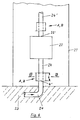
- Fig. 7 shows in cross section the structure of an arrangement the invention in the form of a holder which consists of two modules A, B exists. Regarding details of the structure referred to the explanation of FIGS. 1 and 4.
- the pole shoes 6 are of such a steel plate Thickness, e.g. 5 mm, designed to be the magnetic force of the Shield permanent magnets 5 upwards.
- An additional Shielding can still be done by filling in each of Fig. 7 Areas 14 indicated by dash-dotted lines by means of themselves the length L extending steel pieces take place.
- 8 could the pole piece 6 by an additional Pole 6 'reinforced in its magnetic shielding effect become.
- the additional pole piece 6 ' is corresponding the cross-section of the pole piece 6 angled and exists also made of steel. It has the length of the pole piece 6.
- the two previous versions of the pole pieces according to 7 and 8 apply to both modules and brackets A and B.
- the pole pieces are either between the two housing parts 1, 2 clamped or with at least one of the housing parts connected by gluing.
Landscapes
- Engineering & Computer Science (AREA)
- Chemical & Material Sciences (AREA)
- Mechanical Engineering (AREA)
- Combustion & Propulsion (AREA)
- Organic Chemistry (AREA)
- Chemical Kinetics & Catalysis (AREA)
- General Engineering & Computer Science (AREA)
- General Health & Medical Sciences (AREA)
- Health & Medical Sciences (AREA)
- Toxicology (AREA)
- Life Sciences & Earth Sciences (AREA)
- Hydrology & Water Resources (AREA)
- Environmental & Geological Engineering (AREA)
- Water Supply & Treatment (AREA)
- Physics & Mathematics (AREA)
- Electromagnetism (AREA)
- Power Engineering (AREA)
- Water Treatment By Electricity Or Magnetism (AREA)
Applications Claiming Priority (4)
| Application Number | Priority Date | Filing Date | Title |
|---|---|---|---|
| DE1997139629 DE19739629B4 (de) | 1997-09-10 | 1997-09-10 | Anordnung zur magnetischen Ionisierung eines kohlenwasserstoffhaltigen Treibstoffs, sowie deren Verwendung |
| DE19739629 | 1997-09-10 | ||
| DE1998112667 DE19812667A1 (de) | 1997-09-10 | 1998-03-23 | Verfahren zur magnetischen Ionisierung und Anordnung zur Durchführung dieses Verfahrens |
| DE19812667 | 1998-03-23 |
Publications (1)
| Publication Number | Publication Date |
|---|---|
| EP0902444A1 true EP0902444A1 (fr) | 1999-03-17 |
Family
ID=26039830
Family Applications (1)
| Application Number | Title | Priority Date | Filing Date |
|---|---|---|---|
| EP98115708A Withdrawn EP0902444A1 (fr) | 1997-09-10 | 1998-08-20 | Appareils pour le traitement magnétique de media liquides ou gazeux et applications utilisant ceux-ci |
Country Status (2)
| Country | Link |
|---|---|
| EP (1) | EP0902444A1 (fr) |
| DE (1) | DE19812667A1 (fr) |
Cited By (8)
| Publication number | Priority date | Publication date | Assignee | Title |
|---|---|---|---|---|
| FR2782279A1 (fr) * | 1998-08-13 | 2000-02-18 | Yves Duveau | Dispositif de reequilibrage des champs de coherence des molecules de fluides en circulation et ses applications |
| WO2000062592A3 (fr) * | 1999-03-30 | 2001-03-01 | Stephen Mongan | Procede et appareil permettant d'ameliorer l'efficacite d'un systeme de production d'energie a chaudiere a vapeur |
| WO2001047628A1 (fr) * | 1999-12-24 | 2001-07-05 | Yves Duveau | Dispositif de reequilibrage des champs de coherence des molecules de fluides en circulation et ses applications |
| FR2859394A1 (fr) * | 2003-08-13 | 2005-03-11 | Jen Chieh Wang | Epurateur avec dispositif de rearrangement moleculaire |
| EP1634642A1 (fr) * | 2004-09-01 | 2006-03-15 | Japan System Planning Co., Ltd. | Dispositif d'activation de fluide |
| WO2007006269A1 (fr) * | 2005-07-07 | 2007-01-18 | Tonio Meier | Dispositif et procede pour traiter une biomasse a l'aide d'aimants permanents |
| DE10255135B4 (de) * | 2001-12-03 | 2008-06-05 | Götz, Alfred | Vorrichtung zur Modifikation eines strömungsfähigen Brennstoffs vor dessen Verbrennung |
| DE202013103935U1 (de) | 2013-08-30 | 2013-11-07 | Roe-Novatio Gmbh | Vorrichtung zur Modifizierung eines strömungsfähigen Brennstoffes |
Citations (3)
| Publication number | Priority date | Publication date | Assignee | Title |
|---|---|---|---|---|
| US5366623A (en) * | 1992-09-11 | 1994-11-22 | Colonel Clair | Apparatus for magnetically treating a fluid |
| WO1996010692A1 (fr) * | 1994-10-04 | 1996-04-11 | Magno-Flo Limited | Traitement magnetique de fluides |
| DE4436435A1 (de) * | 1994-10-12 | 1996-04-18 | Sps Engineering & Maschinenbau | Kalkumwandler |
-
1998
- 1998-03-23 DE DE1998112667 patent/DE19812667A1/de not_active Withdrawn
- 1998-08-20 EP EP98115708A patent/EP0902444A1/fr not_active Withdrawn
Patent Citations (3)
| Publication number | Priority date | Publication date | Assignee | Title |
|---|---|---|---|---|
| US5366623A (en) * | 1992-09-11 | 1994-11-22 | Colonel Clair | Apparatus for magnetically treating a fluid |
| WO1996010692A1 (fr) * | 1994-10-04 | 1996-04-11 | Magno-Flo Limited | Traitement magnetique de fluides |
| DE4436435A1 (de) * | 1994-10-12 | 1996-04-18 | Sps Engineering & Maschinenbau | Kalkumwandler |
Cited By (9)
| Publication number | Priority date | Publication date | Assignee | Title |
|---|---|---|---|---|
| FR2782279A1 (fr) * | 1998-08-13 | 2000-02-18 | Yves Duveau | Dispositif de reequilibrage des champs de coherence des molecules de fluides en circulation et ses applications |
| WO2000062592A3 (fr) * | 1999-03-30 | 2001-03-01 | Stephen Mongan | Procede et appareil permettant d'ameliorer l'efficacite d'un systeme de production d'energie a chaudiere a vapeur |
| WO2001047628A1 (fr) * | 1999-12-24 | 2001-07-05 | Yves Duveau | Dispositif de reequilibrage des champs de coherence des molecules de fluides en circulation et ses applications |
| DE10255135B4 (de) * | 2001-12-03 | 2008-06-05 | Götz, Alfred | Vorrichtung zur Modifikation eines strömungsfähigen Brennstoffs vor dessen Verbrennung |
| FR2859394A1 (fr) * | 2003-08-13 | 2005-03-11 | Jen Chieh Wang | Epurateur avec dispositif de rearrangement moleculaire |
| EP1634642A1 (fr) * | 2004-09-01 | 2006-03-15 | Japan System Planning Co., Ltd. | Dispositif d'activation de fluide |
| WO2007006269A1 (fr) * | 2005-07-07 | 2007-01-18 | Tonio Meier | Dispositif et procede pour traiter une biomasse a l'aide d'aimants permanents |
| EA013695B1 (ru) * | 2005-07-07 | 2010-06-30 | Тонио Майер | Устройство и способ обработки биомассы с помощью постоянных магнитов |
| DE202013103935U1 (de) | 2013-08-30 | 2013-11-07 | Roe-Novatio Gmbh | Vorrichtung zur Modifizierung eines strömungsfähigen Brennstoffes |
Also Published As
| Publication number | Publication date |
|---|---|
| DE19812667A1 (de) | 1999-09-30 |
Similar Documents
| Publication | Publication Date | Title |
|---|---|---|
| DE69318693T2 (de) | Magnetischer Konditionierer zur Behandlung von Flüssigkeiten | |
| DE69901035T2 (de) | Ventilanordnung | |
| CH637448A5 (de) | Vorrichtung zur magnetischen behandlung von fluids. | |
| EP0259408B1 (fr) | Agencement de traitement d'eau | |
| DE3135208A1 (de) | Kathodenanordnung zur abstaeubung von material von einem target in einer kathodenzerstaeubungsanlage | |
| EP0902444A1 (fr) | Appareils pour le traitement magnétique de media liquides ou gazeux et applications utilisant ceux-ci | |
| DE3806708A1 (de) | Kalkumwandlungsanlage fuer wasserdruchflossene rohrleitungssysteme fuer haushalte und industrie | |
| DE69420992T2 (de) | Magnetische Stufen-Antikesselsteinvorrichtung | |
| US5269916A (en) | Pipe protector/fluid ionizer employing magnetic condenser for producing concentrated force lines perpendicular to fluid flow | |
| DE60018941T2 (de) | Vorrichtung zur magnetischen modifizierung von flüssigkkeiten | |
| DE19739629B4 (de) | Anordnung zur magnetischen Ionisierung eines kohlenwasserstoffhaltigen Treibstoffs, sowie deren Verwendung | |
| DE4223628A1 (de) | Vorrichtung zur physikalischen Flüssigkeitsbehandlung | |
| DE60313635T2 (de) | Magnetische konditionierungsvorrichtung für dieselbrennstoff | |
| EP0723822A1 (fr) | Appareil de nettoyage des tuyaux d'eau | |
| DE3503691A1 (de) | Magnet-aktivator | |
| AT511345B1 (de) | Vorrichtung zum aufbereiten von gasförmigen oder flüssigen energieträgern | |
| EP1082269B1 (fr) | Systeme de traitement physique de liquide | |
| AT410702B (de) | Magnetischer aufbereiter für fluide brennstoffe | |
| EP1046420A1 (fr) | Dispositif pour le traitement de liquides | |
| DE20101107U1 (de) | Magnetquelle und Kühler | |
| DE4320414A1 (de) | Vorrichtung zur Vermeidung von Verockerungen in Pumpen und Anlagen | |
| WO2018177830A1 (fr) | Ensemble de véhicule automobile comprenant un couvercle de boîte à eau magnétique | |
| DE9309223U1 (de) | Vorrichtung zur Vermeidung von Verockerungen in Pumpen und Anlagen | |
| AT2077U1 (de) | Physikalisches wasserbehandlungssystem | |
| DE29720121U1 (de) | Schmutzabscheider für Rohrleitungen und daran angeschlossene Aggregate |
Legal Events
| Date | Code | Title | Description |
|---|---|---|---|
| PUAI | Public reference made under article 153(3) epc to a published international application that has entered the european phase |
Free format text: ORIGINAL CODE: 0009012 |
|
| AK | Designated contracting states |
Kind code of ref document: A1 Designated state(s): AT BE CH CY DE DK ES FI FR GB GR IE IT LI LU MC NL PT SE |
|
| AX | Request for extension of the european patent |
Free format text: AL;LT;LV;MK;RO;SI |
|
| AKX | Designation fees paid | ||
| STAA | Information on the status of an ep patent application or granted ep patent |
Free format text: STATUS: THE APPLICATION IS DEEMED TO BE WITHDRAWN |
|
| 18D | Application deemed to be withdrawn |
Effective date: 19990918 |
|
| REG | Reference to a national code |
Ref country code: DE Ref legal event code: 8566 |