EP0902456A2 - Korrosionsbeständiges System und Verfahren für ein Plasmaätzgerät - Google Patents
Korrosionsbeständiges System und Verfahren für ein Plasmaätzgerät Download PDFInfo
- Publication number
- EP0902456A2 EP0902456A2 EP98112568A EP98112568A EP0902456A2 EP 0902456 A2 EP0902456 A2 EP 0902456A2 EP 98112568 A EP98112568 A EP 98112568A EP 98112568 A EP98112568 A EP 98112568A EP 0902456 A2 EP0902456 A2 EP 0902456A2
- Authority
- EP
- European Patent Office
- Prior art keywords
- corrosion
- resistant
- gas
- oil
- etching apparatus
- Prior art date
- Legal status (The legal status is an assumption and is not a legal conclusion. Google has not performed a legal analysis and makes no representation as to the accuracy of the status listed.)
- Withdrawn
Links
Images



Classifications
-
- H—ELECTRICITY
- H01—ELECTRIC ELEMENTS
- H01J—ELECTRIC DISCHARGE TUBES OR DISCHARGE LAMPS
- H01J37/00—Discharge tubes with provision for introducing objects or material to be exposed to the discharge, e.g. for the purpose of examination or processing thereof
- H01J37/32—Gas-filled discharge tubes
- H01J37/32009—Arrangements for generation of plasma specially adapted for examination or treatment of objects, e.g. plasma sources
- H01J37/32192—Microwave generated discharge
-
- H—ELECTRICITY
- H01—ELECTRIC ELEMENTS
- H01J—ELECTRIC DISCHARGE TUBES OR DISCHARGE LAMPS
- H01J37/00—Discharge tubes with provision for introducing objects or material to be exposed to the discharge, e.g. for the purpose of examination or processing thereof
- H01J37/32—Gas-filled discharge tubes
- H01J37/32431—Constructional details of the reactor
- H01J37/32458—Vessel
- H01J37/32477—Vessel characterised by the means for protecting vessels or internal parts, e.g. coatings
Definitions
- the present invention relates to an corrosion-resistant system and method for a plasma etching apparatus in which a relatively thick portion(s) on a surface of an object to be etched are locally etched.
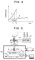
- Fig. 5 is a cross section showing an example of a known plasma etching apparatus
- Fig. 6 is a diagram showing the state of oscillation of a micro wave.
- the plasma etching apparatus performs plasma-discharge using a micro wave.
- a mixed gas containing a halogen-based gas such as CF 4 (carbon tetrafluoride) is supplied to a quartz discharge tube 110 which is mounted on an upper surface of a chamber 100.
- the micro wave M of about 500W is generated or oscillated continuously by a micro wave oscillator 120 toward a wave guide 121, so that the mixed gas in the quarts discharge tube 110 is made into a plasma state, thus producing active species such as fluorine radicals which contribute to etching a silicon wafer W.
- the silicon wafer W is fixedly mounted on a stage 101 which is driven to move in an X-Y direction (i.e., the right and left direction as well as the front and rear direction of the sheet of Fig. 5) by means of an X-Y drive mechanism 130.
- an X-Y direction i.e., the right and left direction as well as the front and rear direction of the sheet of Fig. 5
- a movable stand 132 carrying thereon a stage 101 is driven to move in an X-axis direction by means of a drive motor 131 and in a Y-axis direction by means of a drive motor 133 mounted on the movable stand 132.
- the active species such as fluorine radicals generated by the plasma discharge is jetted from an ejection opening 110a of a quartz discharge tube 110 onto a silicon wafer W.
- the X-Y drive mechanism 130 moves a relatively thick portion of the silicon wafer W (i.e., a portion which forms a surface of the silicon wafer W is formed, and which is relatively thicker than a specified thickness) right under the ejection opening 110a of the quartz discharge tube 110 so that the relatively thick portion can be partially or locally etched.
- part of the active species gas G jetted from the ejection opening 110a might diffuse to etch an inner wall of the chamber 100 as well as the X-Y drive mechanism 130.
- the plasma etching apparatus employs an corrosion-resistant technique.
- the inner wall of the chamber 100 and the X-Y drive mechanism 130 are subjected to corrosion-resistant coating so that they can be prevented from being etched by the active species gas G. Furthermore, even if those portions such as threaded portions, rails, bearings of the X-Y drive mechanism 130, rotation shafts of the drive motors 131, 133 and so on, which are in sliding contact with other elements, are applied with corrosion-resistant coatings, such corrosion-resistant coatings would be liable to be peeled off during a long period of use. Thus, those contacting and sliding portions are coated with a corrosion-resistant oil which does not flake off due to repeated sliding actions.
- the above-mentioned plasma etching apparatus and corrosion-resistant technique have the following problems.
- a first problem is that since the plasma etching apparatus is constructed such that a micro wave M is oscillated or generated continuously so as to produce plasma discharge, as illustrated in Fig. 6, the effective period or life time of the quartz discharge tube 110 is short and the etching rate with respect to the silicon wafer W is low, and the silicon wafer W during etching is liable to be contaminated.
- Fig. 7 is a cross section showing the state of corrosion of the quartz discharge tube 110.
- a mixed gas containing a CF 4 (carbon tetrafluoride) gas for instance is plasma-discharged, there will be generated an active species gas G which contains CF 3 radicals, F radicals, CF 3 cations or positive ions, F anions or negative ions, etc. These radials, positive and negative ions contribute to the localized etching of the silicon wafer W.
- CF 4 carbon tetrafluoride
- the quartz discharge tube 110 continuously absorbs the micro wave, resulting in a rapid rise of the heating temperature of the quartz discharge tube 110.
- the reaction of the active species gas G and a SiO 2 (silicon dioxide) component of the quartz discharge tube 110 is promoted, as shown in Fig. 7, so that the inner wall of the quartz discharge tube 110 is subjected to corrosion, thus forming a hole or holes through the quartz discharge tube 110 in a relatively short period of time.
- the active species gas G reacts with the quarts discharge tube 110 to turn into a SiF 4 (silicon tetrafluoride) gas, thereby reducing the density of the active species gas G ejected to the silicon wafer W to lower the etching rate of the silicon wafer W.
- SiF 4 silicon tetrafluoride
- a second problem is that the above-mentioned corrosion-resistant technique does not provide a satisfactory corrosion resistant effect.
- the X-Y drive mechanism 130 is constructed of various members assembled, so it is impossible to coat every component member with a corrosion-resistant oil.
- the corrosion-resistant oil applied to the sliding portions gradually evaporates so that the base portions underlying the corrosion-resistant coatings are exposed during a long period of use. In order to avoid this, it is necessary to disassemble the chamber 100 and the X-Y drive mechanism 130 regularly or at a predetermined interval and re-coat them with the corrosion-resistant oil.
- the present invention is intended to obviate the above-described problems, and has for its object to provide a corrosion-resistant system and a corrosion-resistant method for a plasma etching apparatus which are capable of reducing or improving the corrosion or erosion phenomena of a discharge tube of the plasma etching apparatus, other equipment or elements in a chamber used for localized etching.
- a corrosion-resistant system for a plasma etching apparatus in which a reactive gas in a discharge tube is plasma-discharged by using a micro wave or a high-frequency wave to produce an active species gas by means of which a relatively thick portion of an object to be etched is locally etched, the corrosion-resistant system comprising:
- the micro wave or the high-frequency wave is oscillated from the oscillation means under the control of the oscillation control means, so that a temperature rise of the discharge tube is decreased in comparison with a continuous oscillation, accordingly suppressing reactions between active species in a plasma and the discharge tube.
- the duty ratio of the pulsed micro wave or high-frequency wave is set to 75% or less, and the pulse frequency of the pulsed micro wave or high-frequency wave is set to 10 kHz or more.
- the pulsed micro wave or high-frequency wave of the duty ratio of 75% or less is oscillated at the pulse frequency of 10 kHz or more.
- the reactive gas includes a halogen-based gas.
- the relatively thick portion of the object to be etched is locally etched effectively by active species, while suppressing the reactions between the discharge tube and the active species of the halogen-based gas.
- the halogen-based gas comprises one selected from the group consisting of a carbon tetrafluoride gas, a sulfur hexafluoride gas, a nitrogen trifluoride gas, and a gas of other fluorocarbon substances.
- the relatively thick portion of the object to be etched is locally etched effectively by active species, while suppressing reactions of the discharge tube with the carbon tetrafluoride gas, the sulfur hexafluoride gas, the nitrogen trifluoride gas, and the gas of other fluorocarbon substances.
- the discharge tube comprises one selected from the group consisting of a quartz discharge tube, a sapphire discharge tube and an alumina discharge tube.
- an corrosion-resistant method for a plasma etching apparatus in which a reactive gas in a discharge tube is plasma-discharged to produce an active species gas by means of which a relatively thick portion of an object to be etched is locally etched,
- the duty ratio of the pulsed micro wave or high-frequency wave is set to 75% or less, and the pulse frequency of the pulsed micro wave or high-frequency wave is set to 10 kHz or more.
- the reactive gas includes a halogen-based gas.
- the halogen-based gas comprises one selected from the group consisting of a carbon tetrafluoride gas, a sulfur hexafluoride gas, a nitrogen trifluoride gas, and a gas of other fluorocarbon substances.
- the discharge tube comprises one selected from the group consisting of a quartz discharge tube, a sapphire discharge tube and an alumina discharge tube.
- an corrosion-resistant system for a plasma etching apparatus comprising:
- the halogen-based gas comprises one selected from the group consisting of a carbon tetrafluoride gas, a sulfur hexafluoride gas, a nitrogen trifluoride gas and a gas of other fluorocarbon substances
- the corrosion-resistant oil comprises a perfluoropolyether oil which is resistant to fluorine.
- the fluorine-containing active species gas diffuses which comprises one selected from the group consisting of a carbon tetrafluoride gas, a sulfur hexafluoride gas, a nitrogen trifluoride gas and a gas of other fluorocarbon substances, such diffusion is blocked by the perfluoropolyether oil which is resistant to fluorine, thus preventing the position control and drive mechanism from being corroded or eroded by the fluorine-containing active species gas.
- the system further comprises:
- the foreign matters mixed in the circulating corrosion-resistant oil can be removed by the filtering means, so that the cleanliness of the corrosion-resistant oil can be maintained for an extended period of time.
- the system further comprises:
- the system further comprises:
- the system further comprises cooling means for cooling the corrosion-resistant oil to a predetermined temperature.
- the corrosion-resistant oil is always maintained at a predetermined temperature by virtue of the cooling means.
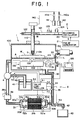
- Fig. 1 schematically illustrates in cross section a corrosion-resistant system for a plasma etching apparatus constructed in accordance with a first embodiment of the present invention.
- the same or corresponding elements of this embodiment as those of Fig. 5 are identified with the same references or symbols.
- a reference numeral 1 designates a plasma etching apparatus
- a reference numeral 2 a corrosion-resistant system according to a first aspect of the present invention
- a reference numeral 3 designates a corrosion-resistant system according to a third aspect of the invention.
- the plasma etching apparatus 1 is substantially of the same construction as that of the plasma etching apparatus shown in Fig. 5.
- the plasma etching apparatus 1 includes a quartz discharge tube 110 mounted on an upper portion of a chamber 100, a wave guide 121 disposed outside of the quartz discharge tube 110, a micro wave oscillators 20 to be described later in detail for oscillating or generating a predetermined micro wave M in the wave guide 121, and an X-Y drive mechanism 130 disposed in the chamber 100.
- the quartz discharge tube 110 is an elongated tubing formed of SiO 2 and has an ejection opening 110a located inside the chamber 100.
- Gas cylinders 141, 142 are connected to the quartz discharge tube 110 through supply pipes 140.
- a CF 4 gas and an O 2 gas are stored in the gas cylinder 141, 142, respectively.
- valves in the supply tubes 140 are opened, the CF 4 gas and the O 2 gas in the gas cylinders 141, 142 are controlled in their flow rates by means of mass flow controllers 141a, 142a, respectively, and mixed with each other to form a mixed reactive gas, which is then supplied to the quartz discharge tube 110.
- the wave guide 121 transmits the micro wave M generated by the micro wave oscillator 20.
- a reflecting plate 122 Inside one end (i.e., the left-hand side end in Fig. 1) of the wave guide 121, there is disposed a reflecting plate 122 in the form of a short plunger which serves to reflect the Micro wave M to thereby form a standing wave.
- disposed in the wave guide 121 are three stub tuners 123 for matching the phase of the micro wave M, and an isolator 124 which bends the reflected micro wave M transmitted to the micro wave oscillator 20 at an angle of 90° with respect to the transmission direction thereof (i.e.,in the direction of the surface of Fig. 1).
- the X-Y drive mechanism 130 comprises a movable stand 132 mounted on a rail 132a on a bottom 100a of the chamber 100 for sliding movement relative thereto, a drive motor 131 for driving the movable stand 132 in an X direction (i.e., in the front and rear direction of Fig. 1) along the rail 132a, and a drive motor 133 mounted on the movable stand 132 for moving the stage 101 in a Y direction (i.e., in the right and left direction of Fig. 1) while supporting the stage 101.
- the drive motors 131, 133 are driven to operate under the control of a computer 135.
- the corrosion-resistant system 2 serves to generate a pulsed micro wave M in the wave guide 121.
- the corrosion-resistant system 2 has an oscillation means in the form of the micro wave oscillator 20, and an oscillation control means in the form of a pulse generator 21.
- the micro wave oscillator 20 can be a well-known device which is turned on to generate a continuous micro wave M when it receives a drive signal S of the high level from the pulse generator 21.
- the micro wave oscillator 20 can generate the continuous micro wave M in the power range of from 100 W to 1 kW.
- the pulse generator 21 generates the pulsed drive signal S for driving the micro wave oscillator 20.
- the pulse width and the pulse frequency of the drive signal S can be arbitrarily adjusted.
- the micro wave oscillator 20 when the pulsed drive signal S is input to the micro wave oscillator 20, as shown in Fig. 2(a), the micro wave oscillator 20 is turned on upon rising of a rectangular wave of the drive signal S, as shown in Fig. 2(b). On the other hand, when the drive signal S falls into the L level, the micro wave oscillator 20 is turned into an Off state.
- the micro wave oscillator 20 continuously oscillates the micro wave M of the power ranging from 100 W to 1 kW only for the length of time of a rectangular wave of the drive signal S. Accordingly, the micro wave oscillator 20 oscillates the pulsed micro wave M in synchronization with the drive signal S from the pulse generator 21, so that changing the pulse width and the frequency of the drive signal S can adjust the duty ratio and the pulse frequency of the micro wave M.
- the corrosion-resistant system 3 serves to prevent the corrosion or erosion of the chamber 100 and the X-Y drive mechanism 130 which constitutes a position control and drive mechanism for controlling the position of an object to be etched.
- the corrosion-resistant system 3 includes a corrosion-resistant oil A in the chamber 100 in which the X-Y drive mechanism 130 is soaked or immersed, a fluid passage in the form of a circulation pipe 30 for circulation of the corrosion-resistant oil A, a filtering means 31, and a valve controller 32 to which an oil level sensor 33, a pH sensor 34, and a pressure sensor 35 are connected.
- the valve controller 32 constitutes a first controller and a second controller as claimed of the present invention.
- the inner wall of the chamber 100 and the surface of the stage 101 are subjected to corrosion-resistant coating such as Teflon coating.
- corrosion-resistant coating such as Teflon coating.
- the corrosion-resistant oil A is stored in the chamber 100 thus applied with the corrosion-resistant coating.
- the corrosion-resistant oil A can be perfluoropolyether oil such as for example FOMBLIN made and sold by the MONTEFLUOS Company, R-95 made and sold by the ULVAC Company, or the like.
- the corrosion-resistant oil A has a property to hardly react with the active species such as F radicals based on halogen-based gases.
- the vapor pressure of the corrosion-resistant oil A is about 10 -13 Torr of which the influence on the etching process can be neglected.
- a pump 4 is mounted on the circulation pipe 30 for circulating the corrosion-resistant oil A through the circulation pipe 30, as indicated by an arrow in Fig. 1.
- the pump 4 is connected with a supply pipe 40 through which the corrosion-resistant oil A in the tank 41 is supplied to the chamber 100 when a valve 50 is opened, the valve 50 cooperating with the pump 4 to constitute an oil feeder means.
- the filtering means 31 serves to filter foreign matter in the form of particles created or contained in the corrosion-resistant oil A.
- the filtering means 31 has two filters 31a and 31b.
- an upstream portion of the circulation pipe 30 is bifurcated into two branch pipes 30a, 30b, and a downstream of the circulation pipe 30is also bifurcated into two branch pipes 30a', 30b'.
- the filter 31a is disposed between and detachably connected with the pipes 30a, 30a'.
- the filter 31b is disposed between and detachably connected with the pipes 30b, 30b'.
- a discharge pipe 42 is mounted to the upstream portion of such a filtering means 31, so that the corrosion-resistant oil A is discharged or exhausted to a tank 43 through the discharge pipe 42 upon opening of an oil discharge means in the form of a valve 53.
- the valve controller 32 serves to control the opening and closing of the valves 50 - 53 based on the detection signals from the oil level sensor 33, the pH sensor 34, and the pressure sensor 35.
- the oil level sensor 33 is mounted on a sidewall of the chamber 100 for generating a detection output signal S1 representative of the detected level or surface position of the corrosion-resistant oil A to the valve controller 32.
- the valve controller 32 determines, upon reception of the detection signal S1, whether the oil level indicated by the detection signal S is a reference level or position L. Then, the valve controller 32 opens the valve 53 when it is determined that the detected oil level indicated by the detection signal S1 is lower than the reference level L, and closes the valve 50 when it is determined that the detected oil level substantially matches or is equal to the reference level L. In addition, the valve controller 32 opens the valve 53 when it is determined that the detected oil level is higher than the reference level L.
- the pH sensor 34 is provided at the upstream portion of the filtering means 31 for detecting the pH of the corrosion-resistant oil A which flows in the circulation pipe 30.
- the pH sensor 34 When the pH of the corrosion-resistant oil A is equal to or less than a predetermined reference pH value (e.g., pH 3), the pH sensor 34 outputs a detection signal S2 to the valve controller 32.
- the valve controller 32 functions to open the valve 53 while closing both the valves 51a, 51b and the valves 52a, 52b upon receipt of the detection signal S2 from the pH sensor 34, and close the valve 53 and open the valve 50 and the valves 51a, 51b (or the valves 52a, 52b) after the lapse of a predetermined time at which the corrosion-resistant oil A is expected to be completely discharged.
- the pressure of the corrosion-resistant oil A at the upstream side of the clogged filter observes or detects this pressure rise, and generates a detection signal S3 to the valve controller 32 when the pressure of the corrosion-resistant oil A rises above a predetermined pressure value.
- the valve controller 32 closes the now open ones of the valve 51a, 51b and valves 52a, 52b and opens the now closed ones of the valves 51a, 51b and valves 52a, 52b upon receipt of the detection signal S3 from the pressure sensor 35.
- a cooling device 36 is mounted on a pipe portion at an upstream portion of the pump 4 for cooling the corrosion-resistant oil A. Specifically, the cooling device 36 observes or monitors the temperature of the corrosion-resistant oil A by means of the temperature sensor 36a mounted on the circulation pipe 30, and cools the corrosion-resistant oil A so as to prevent the vapor pressure of the corrosion-resistant oil A from being raised excessively due to a rise in the temperature thereof.
- the CF 4 gas in the gas cylinder 141 and the O 2 gas in the gas cylinder 142 are supplied in a mixed state to the quartz discharge tube 110 with their flow rates being controlled by means of the mass flow controllers 141a, 142a. Thereafter, the micro wave oscillator 20 is energized to oscillate a micro wave M through which the mixed gas comprising the CF gas and the O 2 gas is plasma-discharged. As a result, there is generated an active species gas G such as CF 3 radicals and F radicals which is ejected to an object to be etched in the form of a silicon wafer W from the ejection opening 110a of the quartz discharge tube 110.
- an active species gas G such as CF 3 radicals and F radicals which is ejected to an object to be etched in the form of a silicon wafer W from the ejection opening 110a of the quartz discharge tube 110.
- the X-Y drive mechanism 130 is controlled by the computer 135 to move the silicon wafer W such that the relatively thick portion on the surface of the silicon wafer W comes right under the ejection opening 110a of the quartz discharge tube 110. In this state, the relatively thick portion of the silicon wafer W is etched by the active species gas G.
- the drive signal S as shown in Fig. 2(a) is input from the pulse generator 21 to the micro wave oscillator 20 to thereby generate a pulsed micro wave M, as shown in Fig. 2(b), by means of which the mixed gas in the quartz discharge tube 110 is plasma-discharged.
- the drive signal S of the pulse generator 21 is adjusted so as to set the duty ratio and the pulse frequency of the micro wave M to respective desired values, and at the same time, the phase of the micro wave M is adjusted by the three stub tuners 123 so that the maximum power of the micro wave M is concentrated in the quartz discharge tube 110.
- Figs. 3(a) and 3(b) show, in cross section, the different states of the plasma generated by the pulsed micro wave M.
- Fig. 3(a) shows the state of a high density plasma generated upon turning on of the micro wave M
- Fig. 3(b) shows the state of the plasma remaining upon turning off of the micro wave M.
- a pulsed micro wave M is oscillated, and upon turning on of the pulsed micro wave M, i.e., when the pulse M1 shown in Fig. 2(b) is applied to the quartz discharge pipe 110, a plasma P is generated in the quartz discharge tube 110, as shown in Fig. 3(a).
- This plasma P maintains its excited state only for a period of time T1 corresponding to the width of the pulse M1, during which active species gases G such as CF 3 radicals, F radicals, etc., are jetted from the ejection opening 110a of the quartz discharge tube 110 toward the silicon wafer W.
- active species gases G such as CF 3 radicals, F radicals, etc.
- the plasma discharge is effected in a pulsed manner.
- Fig. 4 diagrammatically illustrates a rise in the temperature of the quartz discharge tube 110.
- the number or frequency of reactions between the active species gas G in the plasma P and the quartz discharge tube 110 is quite limited in comparison with the conventional apparatus, thus reducing the corrosion or erosion degree of the quartz discharge tube 110 due to the active species gas G and hence increasing the useful life of the quartz discharge tube 110.
- the generation of particles occurring upon erosion or corrosion of the quartz discharge tube 110 decreases sharply, too, so there will be little or no contamination of the silicon wafer W due to particles.
- the active species gas G of a desired density can be ejected to the silicon wafer W, thus making it possible to ensure a desired etching rate of the silicon wafer W.
- micro wave oscillator 20 is turned on in an intermittent manner, it is possible to reduce the electric power consumption during oscillation of the micro wave M.
- a pulsed micro wave M having an output power of about 500 W is oscillated at the duty ratio of 75 % and at the pulse frequency of 10 kHz to generate an active species gas G, which is then ejected to a silicon wafer W having particles attached thereto, the number of the particles having a diameter of less than 1 ⁇ m being not greater than 100 at the original state of the silicon wafer.
- the corrosion-resistant time of the quartz discharge tube 110 and the number of particles attached to the silicon wafer W after the above treatment are examined.
- the quartz discharge tube 110 was destroyed in about 40 hours, and the number of attached particles after about 100 hours also exceeded more than a predetermined measurement limit.
- the corrosion-resistant period of the quartz discharge tube 110 can be increased, and the contamination of the silicon wafer W can be decreased sharply.
- the time of the pulse width T1 of the micro wave M as indicated in Fig. 2(b) be short, but if it is too short, it is impossible to obtain an active species gas G of a desired density.
- a plasma P of a high density as indicated in Fig. 3(a) is produced in the quartz discharge tube 110 during the on-time or oscillation of the micro wave M, i.e., during the time T1 of the pulse width of the micro wave M as indicated in Fig. 2(b).
- the plasma P disappears when the oscillation of the micro wave M is turned off or stopped, i.e., during the period of time T2 indicated in Fig. 2(b).
- the plasma P does not disappear immediately upon turning off of the micro wave M, but there remain charged particles such as ions, electrons, etc., which constitute the plasma P, for some time. For this reason, it is considered that a plasma can be ignited readily by turning on the oscillation of the micro wave M before the charged particles disappear.
- the inventors reached the following conclusion. Namely, as a result of consideration about the duty ratio and the pulse frequency of the micro wave M, which are capable of obtaining a desired density of the active species gas while enhancing the corrosion-resistant effect of the quartz discharge tube 110, as well as the duty ratio and the pulse frequency of the micro wave M, which are capable of expediting smooth plasma discharge while suppressing the rising of the heating temperature of the quartz discharge tube 110 with a limited amount of power consumption, it is preferable to employ a micro wave M having the duty ratio of not greater than 75 % and the pulse frequency of not less than 10 kHz.
- That portion of the active species gas G of a predetermined density ejected from the ejection opening 110a of the quartz discharge tube 110 which diffuses without contributing to the etching of the silicon wafer W is about to etch the inner wall of the chamber 100 and the stage 101.
- the active species gas G is blocked by the corrosion-resistant coatings, so neither the inner wall of the chamber 100 nor the stages 101 are subjected to etching.
- the active species gas G flowing toward the X-Y drive mechanism 130 is about to etch it due to its activity, but it is blocked from advancing toward the X-Y drive mechanism 130 by means of the corrosion-resistant oil A in which the X-Y drive mechanism 130 is immersed.
- the component elements of the X-Y drive mechanism 130 are prevented from being etched by the active species gas G.
- the pump 4 is driven to operate with the valves 50, 52a, 52b, 53 being closed and the valves 51a and 51b opened, so that the corrosion-resistant oil A is thereby forced to circulate through the circulation pipe 30.
- the pressure at the upstream side of the filter 31a e.g., the pressure of the corrosion-resistant oil A near the pressure sensor 35 rises to reach a predetermined pressure value.
- a detection signal S3 is output from the pressure sensor 35 to the valve controller 32, so that the valves 51a, 51b are closed and the valves 52a, 52b are opened under the control of the valve controller 32.
- the corrosion-resistant oil A circulating through the circulation pipe 30 comes to pass through the filter 31b by way of the pipe 30b.
- the clogged filter 31a is disconnected and removed from the pipes 30a, 30a' and replaced with a new filter 31a which is mounted and connected between the pipes 30a and 30a', whereby it is possible to always circulate the corrosion-resistant oil A in a clean state.
- a detection signal S2 is input from the pH sensor 34 to the valve controller 32, so that the valves 51a, 51b and the valves 52a, 52b are closed, and the valve 53 is opened, thereby causing the corrosion-resistant oil A to be discharged or exhausted from the discharge pipe 42 to the tank 43.
- the oil level sensor 33 is maintained in an off state, so that the valve 53 is closed and the valve 52a, 52b are opened after the corrosion-resistant oil A in the chamber 100 and the circulation pipe 30 has been completely exhausted.
- the oil level sensor 33 is turned on so that a detection signal S1 is output from the oil level sensor 33 to the valve controller 32, whereby the valve 50 is opened to supply a new corrosion-resistant oil A in the tank 41 to the chamber 100 through the supply pipe 40.
- the valve 50 is closed.
- the valve controller 32 opens the valve 50 based on a detection signal S1 from the oil level sensor 33, thereby supplying the corrosion-resistant oil A in the tank 41 to the chamber 100.
- the oil level or surface position of the corrosion-resistant oil A in the chamber 100 is always kept to the reference level L.
- the X-Y drive mechanism 130 is subjected to corrosion-resistant treatments or coatings, and the cleanliness of the corrosion-resistant oil A is always maintained clean, and the pH value thereof is also kept substantially constant.
- the plasma etching apparatus 1 was operated for 23 hours without circulating the corrosion-resistant oil A, and then the chamber 100 was opened or released to the ambient atmosphere for 1 hour. Such a severe cyclic operation was carried out for 10 days in a continuous manner. After this long-run operation, the X-Y drive mechanism 130 was disassembled for examination of the level of corrosion or erosion thereof. The X-Y drive mechanism 130 was not corroded at all except for a slight change in the color of the corrosion-resistant oil A, and hence a satisfactory corrosion-resistant effect was obtained.
- water was mixed into the corrosion-resistant oil A at the weight ratio (i.e., ratio of water to oil) of 1 %, and a similar operation was done with the exception that when the pH of the corrosion-resistant oil A decreased to a value of 3 or less, the deteriorated corrosion-resistant oil A was exchanged for a new corrosion-resistant oil under the control of the pH sensor 34 and the valve controller 32. As a result of this operation, it was found that there took place no oxidation phenomenon at all.
- weight ratio i.e., ratio of water to oil
- the CF 4 gas was used for the halogen-based gas constituting the reactive gas, but a SF 6 (sulfur hexafluoride) gas, a NF 3 (nitrogen trifluoride) gas, and other fluorocarbon substances can instead be used, while providing the same or similar corrosion-resistant effect with respect to the active species gas produced from these gases.
- SF 6 sulfur hexafluoride
- NF 3 nitrogen trifluoride
- the plasma etching apparatus oscillating a micro wave has been described, the present invention is applicable to a variety of plasma etching apparatuses which are capable of oscillating a high-frequency wave to generate plasma discharge.
- the quartz discharge tube 110 is subjected to corrosion-resistant treatments or coatings, but every discharge tube such as a sapphire discharge tube, an alumina discharge tube, etc., which might be etched by active species gases, can be treated by corrosion-resistant coatings.
- the corrosion-resistant coating has been applied to the inner wall of the chamber 100 and the stage 101 alone which are not soaked in the corrosion-resistant oil A, but the X-Y drive mechanism 130, the valves 50 - 53, etc., which are soaked in the corrosion-resistant oil A, can also be applied with corrosion-resistant coatings, thus improving the overall corrosion-resistant effect
- the perfluoropolyether oil has been used for the corrosion-resistant oil
- any corrosion-resistant oil can be employed which has a vapor pressure equal to or less than 10 -6 Torr, and hence the corrosion-resistant oil to be used is not limited to the perfluoropolyether oil.
- the present invention provides the following remarkable advantages.
- the discharge tube is only exposed to a plasma for a period of time corresponding to a pulse width of a micro wave or a high-frequency wave, so the temperature of the discharge tube heated by such a plasma does not rise rapidly.
- the corrosion or erosion of the discharge tube can be reduced, accordingly prolonging the useful life of the discharge tube.
- an object to be etched can be etched by a desired etching rate.
- the reduced corrosion or erosion of the discharge tube serves to suppress the generation of particles of impurities etc., thus decreasing the contamination of an object to be etched.
- micro wave or the high-frequency wave oscillated in a pulsed manner serves to reduce the electric power consumption.
- the chamber and the position control and drive mechanism are covered with the corrosion-resistant coating and the corrosion-resistant oil substantially in a complete manner so as to ensure their corrosion resistance, as a consequence of which the life time of the plasma etching apparatus can be prolonged and the frequency of maintenance can be reduced.
- the level or surface of the corrosion-resistant oil can always be maintained constant, thus preventing exposure of the position control and drive mechanism. This serves to prevent the position control and drive mechanism from being corroded or eroded by the active species gas in a reliable manner.
- the corrosion-resistant oil is discharged or exhausted from the chamber by an oil discharge means when the pH of the corrosion-resistant oil decreases below the predetermined reference pH value, as a consequence of which it is possible to avoid such a situation that the position control and drive mechanism would be oxidized by acids in the corrosion-resistant oil.
Landscapes
- Physics & Mathematics (AREA)
- Engineering & Computer Science (AREA)
- Plasma & Fusion (AREA)
- Chemical & Material Sciences (AREA)
- Analytical Chemistry (AREA)
- Drying Of Semiconductors (AREA)
- ing And Chemical Polishing (AREA)
- Preventing Corrosion Or Incrustation Of Metals (AREA)
Applications Claiming Priority (3)
| Application Number | Priority Date | Filing Date | Title |
|---|---|---|---|
| JP256075/97 | 1997-09-04 | ||
| JP9256075A JPH1180975A (ja) | 1997-09-04 | 1997-09-04 | プラズマエッチング装置の耐食システム及びその方法 |
| JP25607597 | 1997-09-04 |
Publications (2)
| Publication Number | Publication Date |
|---|---|
| EP0902456A2 true EP0902456A2 (de) | 1999-03-17 |
| EP0902456A3 EP0902456A3 (de) | 2002-06-19 |
Family
ID=17287549
Family Applications (1)
| Application Number | Title | Priority Date | Filing Date |
|---|---|---|---|
| EP98112568A Withdrawn EP0902456A3 (de) | 1997-09-04 | 1998-07-07 | Korrosionsbeständiges System und Verfahren für ein Plasmaätzgerät |
Country Status (5)
| Country | Link |
|---|---|
| US (1) | US6316369B1 (de) |
| EP (1) | EP0902456A3 (de) |
| JP (1) | JPH1180975A (de) |
| KR (1) | KR100281950B1 (de) |
| TW (1) | TW426755B (de) |
Cited By (1)
| Publication number | Priority date | Publication date | Assignee | Title |
|---|---|---|---|---|
| WO2008151335A1 (de) * | 2007-06-13 | 2008-12-18 | Ulrich Traxlmayr | Vorrichtung zur erzeugung von plasma oder radikalen mittels mikrowellen |
Families Citing this family (6)
| Publication number | Priority date | Publication date | Assignee | Title |
|---|---|---|---|---|
| US6451217B1 (en) * | 1998-06-09 | 2002-09-17 | Speedfam-Ipec Co., Ltd. | Wafer etching method |
| KR102064914B1 (ko) | 2013-03-06 | 2020-01-10 | 삼성전자주식회사 | 식각 공정 장치 및 식각 공정 방법 |
| JP7233348B2 (ja) * | 2019-09-13 | 2023-03-06 | 東京エレクトロン株式会社 | プラズマ処理装置及びプラズマ処理方法 |
| CN112908822B (zh) * | 2019-12-04 | 2024-04-05 | 中微半导体设备(上海)股份有限公司 | 形成耐等离子体涂层的方法、零部件和等离子体处理装置 |
| WO2021222726A1 (en) * | 2020-05-01 | 2021-11-04 | Mattson Technology, Inc. | Methods and apparatus for pulsed inductively coupled plasma for surface treatment processing |
| CN117990600B (zh) * | 2024-01-31 | 2024-07-09 | 江苏博兰杰石英科技有限公司 | 一种石英瓶耐腐蚀性检测装置 |
Family Cites Families (21)
| Publication number | Priority date | Publication date | Assignee | Title |
|---|---|---|---|---|
| US3323947A (en) * | 1964-12-17 | 1967-06-06 | Bell Telephone Labor Inc | Method for making electrode connections to potassium tantalate-niobate |
| GB2105729B (en) * | 1981-09-15 | 1985-06-12 | Itt Ind Ltd | Surface processing of a substrate material |
| JPS6175529A (ja) * | 1984-09-21 | 1986-04-17 | Toshiba Corp | ドライエツチング方法及び装置 |
| GB2212974B (en) | 1987-11-25 | 1992-02-12 | Fuji Electric Co Ltd | Plasma processing apparatus |
| US5024716A (en) | 1988-01-20 | 1991-06-18 | Canon Kabushiki Kaisha | Plasma processing apparatus for etching, ashing and film-formation |
| US5015330A (en) * | 1989-02-28 | 1991-05-14 | Kabushiki Kaisha Toshiba | Film forming method and film forming device |
| EP0395415B1 (de) | 1989-04-27 | 1995-03-15 | Fujitsu Limited | Gerät und Verfahren zur Bearbeitung einer Halbleitervorrichtung unter Verwendung eines durch Mikrowellen erzeugten Plasmas |
| EP0478283B1 (de) | 1990-09-26 | 1996-12-27 | Hitachi, Ltd. | Verfahren und Gerät zur Bearbeitung mittels Mikrowellenplasma |
| US5262610A (en) * | 1991-03-29 | 1993-11-16 | The United States Of America As Represented By The Air Force | Low particulate reliability enhanced remote microwave plasma discharge device |
| US5376224A (en) | 1992-02-27 | 1994-12-27 | Hughes Aircraft Company | Method and apparatus for non-contact plasma polishing and smoothing of uniformly thinned substrates |
| JP3026704B2 (ja) * | 1993-07-29 | 2000-03-27 | 富士通株式会社 | マグネトロン発振出力制御装置及びプラズマ処理方法 |
| EP0648861A1 (de) * | 1993-10-15 | 1995-04-19 | Applied Materials, Inc. | Anlage zur Behandlung von Halbleitern |
| US5468341A (en) * | 1993-12-28 | 1995-11-21 | Nec Corporation | Plasma-etching method and apparatus therefor |
| US5498308A (en) * | 1994-02-25 | 1996-03-12 | Fusion Systems Corp. | Plasma asher with microwave trap |
| US5423942A (en) * | 1994-06-20 | 1995-06-13 | Texas Instruments Incorporated | Method and apparatus for reducing etching erosion in a plasma containment tube |
| JP3438109B2 (ja) * | 1994-08-12 | 2003-08-18 | 富士通株式会社 | プラズマ処理装置及びプラズマ処理方法 |
| US5641375A (en) * | 1994-08-15 | 1997-06-24 | Applied Materials, Inc. | Plasma etching reactor with surface protection means against erosion of walls |
| JP2845163B2 (ja) | 1994-10-27 | 1999-01-13 | 日本電気株式会社 | プラズマ処理方法及びその装置 |
| JPH08335573A (ja) | 1995-04-05 | 1996-12-17 | Tokyo Electron Ltd | プラズマ成膜方法及びその装置 |
| JP3582916B2 (ja) * | 1995-10-14 | 2004-10-27 | スピードファム株式会社 | プラズマエッチング装置 |
| US5936352A (en) | 1995-11-28 | 1999-08-10 | Nec Corporation | Plasma processing apparatus for producing plasma at low electron temperatures |
-
1997
- 1997-09-04 JP JP9256075A patent/JPH1180975A/ja not_active Withdrawn
-
1998
- 1998-07-07 KR KR1019980027193A patent/KR100281950B1/ko not_active Expired - Fee Related
- 1998-07-07 EP EP98112568A patent/EP0902456A3/de not_active Withdrawn
- 1998-08-31 TW TW087114381A patent/TW426755B/zh not_active IP Right Cessation
-
2000
- 2000-03-30 US US09/539,114 patent/US6316369B1/en not_active Expired - Fee Related
Cited By (1)
| Publication number | Priority date | Publication date | Assignee | Title |
|---|---|---|---|---|
| WO2008151335A1 (de) * | 2007-06-13 | 2008-12-18 | Ulrich Traxlmayr | Vorrichtung zur erzeugung von plasma oder radikalen mittels mikrowellen |
Also Published As
| Publication number | Publication date |
|---|---|
| JPH1180975A (ja) | 1999-03-26 |
| US6316369B1 (en) | 2001-11-13 |
| EP0902456A3 (de) | 2002-06-19 |
| TW426755B (en) | 2001-03-21 |
| KR100281950B1 (ko) | 2001-03-02 |
| KR19990029246A (ko) | 1999-04-26 |
Similar Documents
| Publication | Publication Date | Title |
|---|---|---|
| US7115185B1 (en) | Pulsed excitation of inductively coupled plasma sources | |
| KR970000417B1 (ko) | 드라이 에칭방법 및 드라이 에칭장치 | |
| KR101191549B1 (ko) | 기판 세정 방법, 기판 세정 장치 및 프로그램 기록 매체 | |
| JP4880194B2 (ja) | ガスのプラズマ処理装置およびプラズマ処理方法 | |
| JP4490704B2 (ja) | プラズマ処理方法 | |
| EP1162646A2 (de) | Plasmabehandlungsgerät und -verfahren | |
| KR20040105567A (ko) | 유기층 제거 방법 및 장치 | |
| JP2006287228A (ja) | セルフクリーニングが可能な半導体処理装置 | |
| US6316369B1 (en) | Corrosion-resistant system and method for a plasma etching apparatus | |
| KR19990071626A (ko) | 사파이어플라즈마애셔에서기판으로부터잔류물을제거하는방법및그장치 | |
| JP2004531906A (ja) | 半導体処理のための方向付けられたガスの射出装置 | |
| US6708700B2 (en) | Cleaning of semiconductor processing chambers | |
| JP2000200771A (ja) | プラズマ処理方法 | |
| JP4490938B2 (ja) | プラズマ処理装置 | |
| JP2004223365A (ja) | ガス処理装置 | |
| JP4169854B2 (ja) | ウエハ平坦化方法 | |
| JP4673457B2 (ja) | プラズマ処理方法 | |
| JPWO2020012693A1 (ja) | プラズマ処理方法及びプラズマ処理装置 | |
| US5575888A (en) | Sidewall passivation by oxidation during refractory-metal plasma etching | |
| KR102679694B1 (ko) | 부품 세정 장치 및 부품 세정 방법 | |
| JPH06318579A (ja) | ドライクリーニング方法 | |
| JP2005238206A (ja) | 有機ハロゲン化合物放電分解装置およびその方法 | |
| JP2003197605A (ja) | ドライエッチング装置およびそのドライクリーニング方法 | |
| JP2005150258A (ja) | プラズマcvd装置のクリーニング方法 | |
| JP4716763B2 (ja) | プラズマ処理装置 |
Legal Events
| Date | Code | Title | Description |
|---|---|---|---|
| PUAI | Public reference made under article 153(3) epc to a published international application that has entered the european phase |
Free format text: ORIGINAL CODE: 0009012 |
|
| AK | Designated contracting states |
Kind code of ref document: A2 Designated state(s): AT BE CH CY DE DK ES FI FR GB GR IE IT LI LU MC NL PT SE |
|
| AX | Request for extension of the european patent |
Free format text: AL;LT;LV;MK;RO;SI |
|
| PUAL | Search report despatched |
Free format text: ORIGINAL CODE: 0009013 |
|
| RIC1 | Information provided on ipc code assigned before grant |
Free format text: 7H 01J 37/32 A, 7H 01J 37/20 B |
|
| AK | Designated contracting states |
Kind code of ref document: A3 Designated state(s): AT BE CH CY DE DK ES FI FR GB GR IE IT LI LU MC NL PT SE |
|
| AX | Request for extension of the european patent |
Free format text: AL;LT;LV;MK;RO;SI |
|
| STAA | Information on the status of an ep patent application or granted ep patent |
Free format text: STATUS: THE APPLICATION HAS BEEN WITHDRAWN |
|
| 18W | Application withdrawn |
Withdrawal date: 20020906 |