EP0902496A2 - Mode filter for the connection of two electromagnetic waveguides - Google Patents
Mode filter for the connection of two electromagnetic waveguides Download PDFInfo
- Publication number
- EP0902496A2 EP0902496A2 EP98402039A EP98402039A EP0902496A2 EP 0902496 A2 EP0902496 A2 EP 0902496A2 EP 98402039 A EP98402039 A EP 98402039A EP 98402039 A EP98402039 A EP 98402039A EP 0902496 A2 EP0902496 A2 EP 0902496A2
- Authority
- EP
- European Patent Office
- Prior art keywords
- cross
- mode filter
- pipe section
- interior
- filter according
- Prior art date
- Legal status (The legal status is an assumption and is not a legal conclusion. Google has not performed a legal analysis and makes no representation as to the accuracy of the status listed.)
- Granted
Links
Images


Classifications
-
- H—ELECTRICITY
- H01—ELECTRIC ELEMENTS
- H01P—WAVEGUIDES; RESONATORS, LINES, OR OTHER DEVICES OF THE WAVEGUIDE TYPE
- H01P5/00—Coupling devices of the waveguide type
- H01P5/08—Coupling devices of the waveguide type for linking dissimilar lines or devices
- H01P5/082—Transitions between hollow waveguides of different shape, e.g. between a rectangular and a circular waveguide
Definitions
- the invention relates to a mode filter for connecting two electromagnetic waveguides with different cross-sectional shapes, consisting of a piece of pipe that has openings at its ends, the cross sections of which Cross sections correspond to the two different waveguides and its interior passes from one cross-sectional shape to the other, in which the interior of the Pipe piece means to minimize unwanted modes of the transmitted electromagnetic waves are present.
- Waveguides are used because of the low attenuation of those to be transmitted electromagnetic waves especially at higher frequencies, for example as Supply lines used for antennas.
- the damping can, however, under certain circumstances still be too high if, for example, the transmission power is low or if no sufficiently large reflectors can be used.
- the waveguide can then operated overmoded, d. H. with higher frequencies than for their Dimensions provided per se.
- d. H. With higher frequencies than for their Dimensions provided per se.
- the waveguides next to the desired basic fashion also stimulates unwanted, higher modes. That leads to one Ripples of the group delay and the amplitude of the basic mode, d. H. to a Fluctuation in its amplitude. That cannot be completely prevented by the Use of mode filters can be minimized.
- a mode filter as described at the beginning, is made by the company RFS crememetal, Hanover, distributed. With such a mode filter, the unwanted modes uncoupled. For this purpose are in the wall of the mode filter designed as a tube piece Panels attached that lead to absorbers attached to the outside of the pipe section. The Absorbers are cooled during operation.
- the invention has for its object the mode filter described in his Simplify construction.
- This mode filter is very simple. It can be in the usual, for example for Transitions of known technology are made.
- the two flat, electrically conductive Elements that are, for example, sheets or pins can can be easily installed and adjusted, for example, by slots in the pipe section. It has surprisingly found that just by the correctly positioned flat elements the greatest possible suppression of undesired modes is achieved. Become an absorber not required. Cooling is not necessary as there is no significant heating takes place.
- the mode filter can therefore also be used with advantage for high outputs. The Ripple of the group delay and the amplitude of the desired to be transmitted Wave is thus easily acceptable to a wide range of performance Minimum reduced.
- Fig. 1 shows a schematic representation of an arrangement with a mode filter according to the Invention.
- Fig. 4 shows the image of Fig. 2 without interior.
- FIG. 5 shows a section through FIG. 4 along the line V - V.
- Fig. 6 shows a section through Fig. 4 along the line VI - VI.
- Fig. 7 shows a section through Fig. 2 along the line VII - VII.
- the "flat elements" present in the mode filter can be sheets.
- the sheets can also be comb-like in the interior of the mode filter without recesses pointing "tines". However, each element can also be made side by side arranged pins or strips exist.
- the elements are marked with the word "flat" flat structures marked. They run at the same thickness in the pipe section i. w. in the radial direction. Representing all possible embodiments is in following the sheet as a "flat element" described.
- a parabolic reflector 1 of an antenna is shown on the under Interposition of a mode filter 2 an electromagnetic waveguide 3 connected.
- the cross-sectional shapes of the waveguide 3 and the waveguide input the antenna itself is arbitrary.
- Has in the embodiment explained below 5 has an elliptical cross section, while the waveguide entrance 6 is rectangular.
- the mode filter 2 connects accordingly an elliptical waveguide 3 with a rectangular waveguide entrance, the light Dimensions are also significantly smaller than that of the waveguide 3.
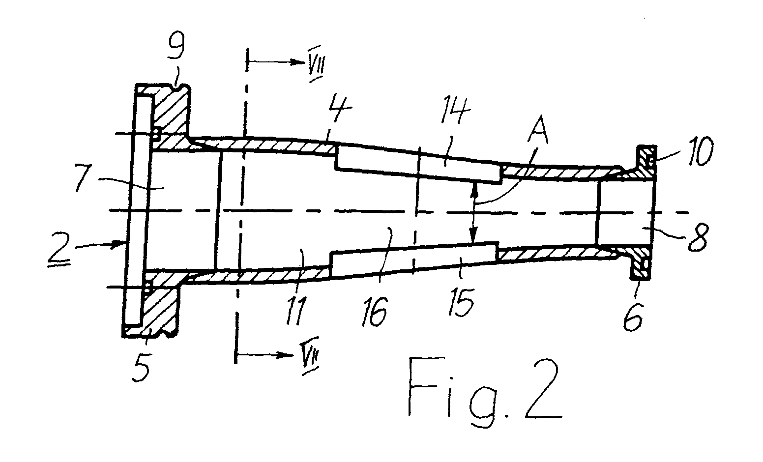
- the mode filter 2 is designed according to FIG. 2 as a pipe section 4, at its two ends Flanges 5 and 6 are attached.
- the flange 5 is used to connect the waveguide 3. He has a central, continuous opening 7 with an elliptical cross section that is the same the electrically effective cross section of the waveguide 3.
- the flange 6 At the opposite end of the pipe section 4 is the flange 6 with a central, continuous opening 8, whose rectangular cross section is equal to the electrically effective cross section of the Waveguide input of the antenna is.
- the mode filter 2 can Reflector 1 are attached.
- In the circumferential grooves 9 and 10 of the two flanges 5 and 6 sealing elements can be arranged.
- the flanges 5 and 6 can be made to size with conventional technology.
- the pipe section 4 is expediently produced by electrodeposition on a core, whose outer contour exactly the desired contour of the interior 11 of the pipe section 4 or the mode filter 2 corresponds.
- the two flanges 5 and 6 are the same galvanized to the pipe section 4 It is also in the manufacture of the pipe section 4 possible, in its wall at two diametrically opposite points Form slots 12 and 13 (Fig. 4), which serve to receive sheets 14 and 15.
- the interior 11 of the pipe section 4 is shaped so that preferably one Continuous, seamless transition from the elliptical cross section of the waveguide 3 to rectangular cross section of the waveguide input of the antenna results.
- the interior 11 could also be provided with steps. There would then be a graded transition from one cross-sectional shape to another.
- the sheets 14 and 15 are arranged. They protrude radially into the pipe section 4 and run in the same axial direction. Their axial length is small in relation to the length of the Pipe section 4.
- the sheets 14 and 15 are aligned with one another and lie one against the other according to FIG. 7 diametrically opposite in the same plane. They are through a space 16 separated from each other, which can be constant over their entire axial length.
- Gap 16 can also be designed conically according to FIG. 2. He can with about conical course also have steps. This is useful, for example, when using Pins in place of the sheets.
- the waveguide 3 and the opening 7 of the flange 5 have an elliptical cross section.
- the sheets 14 and 15 are preferably in the major axis of the ellipse, as in FIG Fig. 7 is shown.
- the distance A between the two sheets 14 and 15 and their axial length are directed according to the frequency of the fundamental wave guided in the waveguide 3. It is adjusted by two sheets 14 and 15 dimensioned so that undesirable higher modes largely are suppressed and that their influence on the fundamental wave is minimized. That means, that the size of the "ripples" created by superimposing the different modes is kept as small as possible so that the ripple of the fundamental wave within narrow limits can be held.
- the sheets 14 and 15 are made of electrically highly conductive material, such as copper or Aluminum. In a preferred embodiment, they are made of bronze or brass manufactured. You can use for example after completion of the pipe section 4 connected flanges 5 and 6 through the slots 12 and 13 of the pipe section 4 in the same can be inserted. Your position, i.e. their distance A from each other will for example, by means of a template protruding into the pipe section 4. In in this position, the sheets 14 and 15 are firmly connected to the pipe section 4, for example soldered. Finally, 4 projecting parts the sheets 14 and 15 are separated so that there is a smooth surface for the pipe section 4 results.
- the template only needs once for a certain type of mode filter to be made. It can then be used to produce a large reproducible Number of mode filters can be used.
- the sheets 14 and 15 as well as the flanges 5 and 6 when galvanizing the pipe section 4 with be electroplated.
- the corresponding core needs for one type of mode filter as well as the template mentioned above, to be made only once.
Landscapes
- Control Of Motors That Do Not Use Commutators (AREA)
- Filters And Equalizers (AREA)
Abstract
Es wird ein Modenfilter zur Verbindung von zwei elektromagnetischen Hohlleitern mit
unterschiedlichen Querschnittsformen angegeben. Es besteht aus einem Rohrstück (4), das
an seinen Enden Öffnungen hat, deren Querschnitte den Querschnitten der beiden
unterschiedlichen Hohlleiter entsprechen und dessen Innenraum (11) von der einen
Querschnittsform in die andere übergeht. Im Innenraum des Rohrstücks (4) sind zur
Minimierung unerwünschter Moden der zu übertragenden elektromagnetischen Wellen im
Übergangsbereich zwischen den beiden Querschnittsformen zwei in radialer Richtung in
dasselbe hineinragende und in seiner Achsrichtung verlaufende, flache Elemente (14,15)
aus elektrisch gut leitendem Material angebracht. Die Elemente (14,15) sind von der
Wandung des Rohrstücks (4) ausgehend durch einen Zwischenraum (16) voneinander
getrennt und miteinander fluchtend in der gleichen Ebene einander diametral gegenüber
liegend angeordnet. Ihre axiale Länge ist kurz im Verhältnis zur Länge des Rohrstücks (4)
und ebenso wie ihr Abstand (A) voneinander entsprechend einer Minimierung der Welligkeit
von Gruppenlaufzeit und Amplitude der zu übertragenden Welle bemessen, welche durch
Überlagerung aller angeregten Moden hervorgerufen wird.
Description
Die Erfindung bezieht sich auf ein Modenfilter zur Verbindung von zwei elektromagnetischen Hohlleitern mit unterschiedlichen Querschnittsformen, bestehend aus einem Rohrstück, das an seinen Enden Öffnungen hat, deren Querschnitte den Querschnitten der beiden unterschiedlichen Hohlleiter entsprechen und dessen Innenraum von der einen Querschnittsform in die andere übergeht, bei welchem im Innenraum des Rohrstücks Mittel zur Minimierung unerwünschter Moden der zu übertragenden elektromagnetischen Wellen vorhanden sind.The invention relates to a mode filter for connecting two electromagnetic waveguides with different cross-sectional shapes, consisting of a piece of pipe that has openings at its ends, the cross sections of which Cross sections correspond to the two different waveguides and its interior passes from one cross-sectional shape to the other, in which the interior of the Pipe piece means to minimize unwanted modes of the transmitted electromagnetic waves are present.
Hohlleiter werden wegen der geringen Dämpfung der zu übertragenden elektromagnetischen Wellen insbesondere bei höheren Frequenzen beispielsweise als Versorgungsleitungen für Antennen verwendet. Die Dämpfung kann aber unter Umständen immer noch zu hoch sein, wenn beispielsweise die Sendeleistung gering ist oder wenn keine ausreichend großen Reflektoren verwendet werden können. Die Hohlleiter können dann übermodiert betrieben werden, d. h. mit höheren Frequenzen als für ihre Abmessungen an sich vorgesehen. Dadurch werden in den Hohlleitern neben dem gewünschten Grundmode auch unerwünschte, höhere Moden angeregt. Das führt zu einer Welligkeit (ripples) der Gruppenlaufzeit und der Amplitude des Grundmodes, d. h. zu einer Schwankung der Amplitude desselben. Das kann nicht vollständig verhindert, durch den Einsatz von Modenfiltern aber minimiert werden.Waveguides are used because of the low attenuation of those to be transmitted electromagnetic waves especially at higher frequencies, for example as Supply lines used for antennas. The damping can, however, under certain circumstances still be too high if, for example, the transmission power is low or if no sufficiently large reflectors can be used. The waveguide can then operated overmoded, d. H. with higher frequencies than for their Dimensions provided per se. As a result, in the waveguides next to the desired basic fashion also stimulates unwanted, higher modes. That leads to one Ripples of the group delay and the amplitude of the basic mode, d. H. to a Fluctuation in its amplitude. That cannot be completely prevented by the Use of mode filters can be minimized.
Ein Modenfilter, wie es eingangs beschrieben ist, wird von der Firma RFS kabelmetal, Hannover, vertrieben. Mit einem solchen Modenfilter werden die unerwünschten Moden ausgekoppelt. Dazu sind in der Wandung des als Rohrstück ausgebildeten Modenfilters Blenden angebracht, die zu außen am Rohrstück befestigten Absorbern führen. Die Absorber werden während des Betriebes gekühlt. A mode filter, as described at the beginning, is made by the company RFS kabelmetal, Hanover, distributed. With such a mode filter, the unwanted modes uncoupled. For this purpose are in the wall of the mode filter designed as a tube piece Panels attached that lead to absorbers attached to the outside of the pipe section. The Absorbers are cooled during operation.
Der Erfindung liegt die Aufgabe zugrunde, das eingangs geschilderte Modenfilter in seinem Aufbau zu vereinfachen.The invention has for its object the mode filter described in his Simplify construction.
Diese Aufgabe wird gemäß der Erfindung dadurch gelöst, daß im Innenraum des Rohrstücks im Übergangsbereich zwischen den beiden Querschnittsformen zwei in radialer Richtung in dasselbe hineinragende und in seiner Achsrichtung verlaufende, flache Elemente aus elektrisch gut leitendem Material angebracht sind, die von der Wandung des Rohrstücks ausgehend durch einen Zwischenraum voneinander getrennt und miteinander fluchtend in der gleichen Ebene einander diametral gegenüber liegend angeordnet sind, deren axiale Länge kurz ist im Verhältnis zur Länge des Rohrstücks und deren axiale Länge sowie ihr Abstand voneinander entsprechend einer Minimierung der Welligkeit von Gruppenlaufzeit und Amplitude der zu übertragenden Welle bemessen sind, welche durch Überlagerung aller angeregten Moden hervorgerufen wird.This object is achieved according to the invention in that in the interior of the Pipe piece in the transition area between the two cross-sectional shapes two in radial Direction in the same protruding and in its axial direction, flat Elements made of electrically highly conductive material are attached by the wall of the Pipe section separated by an intermediate space and with each other are aligned diametrically opposite one another in the same plane, their axial length is short in relation to the length of the pipe section and their axial length and their distance from each other in accordance with a minimization of the ripple of Group transit time and amplitude of the wave to be transmitted are measured by Superposition of all excited modes is caused.
Dieses Modenfilter ist sehr einfach aufgebaut. Es kann in üblicher, beispielsweise für Übergänge bekannter Technik hergestellt werden. Die beiden flachen, elektrisch leitenden Elemente, bei denen es sich beispielsweise um Bleche oder Stifte handelt, können beispielsweise durch Schlitze im Rohrstück leicht montiert und justiert werden. Es hat sich überraschend herausgestellt, daß allein durch die richtig positionierten flachen Elemente eine weitestgehende Unterdrückung unerwünschter Moden erreicht wird. Absorber werden nicht benötigt. Eine Kühlung ist nicht erforderlich, da keine wesentliche Erwärmung stattfindet. Das Modenfilter ist daher mit Vorteil auch für hohe Leistungen verwendbar. Die Welligkeit der Gruppenlaufzeit und der Amplitude der gewünschten, zu übertragenden Welle wird so für einen breiten Leistungsbereich auf einfache Weise auf ein akzeptables Minimum reduziert.This mode filter is very simple. It can be in the usual, for example for Transitions of known technology are made. The two flat, electrically conductive Elements that are, for example, sheets or pins can can be easily installed and adjusted, for example, by slots in the pipe section. It has surprisingly found that just by the correctly positioned flat elements the greatest possible suppression of undesired modes is achieved. Become an absorber not required. Cooling is not necessary as there is no significant heating takes place. The mode filter can therefore also be used with advantage for high outputs. The Ripple of the group delay and the amplitude of the desired to be transmitted Wave is thus easily acceptable to a wide range of performance Minimum reduced.
Ein Ausführungsbeispiel des Erfindungsgegenstandes ist in den Zeichnungen dargestellt.An embodiment of the subject of the invention is shown in the drawings.
Es zeigen:Show it:
Fig. 1 in schematischer Darstellung eine Anordnung mit einem Modenfilter nach der Erfindung.Fig. 1 shows a schematic representation of an arrangement with a mode filter according to the Invention.
Fig. 2 und 3 Längsschnitte durch das Modenfilter in zwei unterschiedlichen Ebenen in vergrößerter Darstellung.2 and 3 longitudinal sections through the mode filter in two different levels in enlarged view.
Fig. 4 das Bild nach Fig 2 ohne Innenleben.Fig. 4 shows the image of Fig. 2 without interior.
Fig. 5 einen Schnitt durch Fig. 4 längs der Linie V - V.5 shows a section through FIG. 4 along the line V - V.
Fig. 6 einen Schnitt durch Fig. 4 längs der Linie VI - VI.Fig. 6 shows a section through Fig. 4 along the line VI - VI.
Fig. 7 einen Schnitt durch Fig. 2 längs der Linie VII - VII. Fig. 7 shows a section through Fig. 2 along the line VII - VII.
Die im Modenfilter vorhandenen "flachen Elemente" können Bleche sein. Die Bleche können ohne Ausnehmungen aber auch kammartig mit in den Innenraum des Modenfilters weisenden "Zinken" ausgeführt sein. Jedes Element kann aber auch aus nebeneinander angeordneten Stiften oder Streifen bestehen. Die Elemente sind mit dem Wort "flach" als flächige Gebilde gekennzeichnet. Sie verlaufen bei gleichbleibender Dicke im Rohrstück i. w. in radialer Richtung. Stellvertretend für alle möglichen Ausführungsformen wird im folgenden das Blech als "flaches Element" beschrieben.The "flat elements" present in the mode filter can be sheets. The sheets can also be comb-like in the interior of the mode filter without recesses pointing "tines". However, each element can also be made side by side arranged pins or strips exist. The elements are marked with the word "flat" flat structures marked. They run at the same thickness in the pipe section i. w. in the radial direction. Representing all possible embodiments is in following the sheet as a "flat element" described.
In Fig. 1 ist ein parabolischer Reflektor 1 einer Antenne dargestellt, an den unter
Zwischenschaltung eines Modenfilters 2 ein elektromagnetischer Hohlleiter 3
angeschlossen ist. Die Querschnittsformen des Hohlleiters 3 und des Hohlleitereingangs
der Antenne sind an sich beliebig. In dem im folgenden erläuterten Ausführungsbeispiel hat
der Hohlleiter 3 gemäß Fig. 5 einen elliptischen Querschnitt, während der Hohlleitereingang
der Antenne gemäß Fig. 6 rechteckig ist. Das Modenfilter 2 verbindet dementsprechend
einen elliptischen Hohlleiter 3 mit einem rechteckigen Hohlleitereingang, dessen lichte
Abmessungen außerdem deutlich kleiner als die des Hohlleiters 3 sind.In Fig. 1, a parabolic reflector 1 of an antenna is shown on the under
Interposition of a
Das Modenfilter 2 ist gemäß Fig. 2 als Rohrstück 4 ausgebildet, an dessen beiden Enden
Flansche 5 und 6 angebracht sind. Der Flansch 5 dient zum Anschluß des Hohlleiters 3. Er
hat eine zentrale, durchgehende Öffnung 7 mit einem elliptischen Querschnitt, der gleich
dem elektrisch wirksamen Querschnitt des Hohlleiters 3 ist. Am gegenüber liegenden Ende
des Rohrstücks 4 befindet sich der Flansch 6 mit einer zentralen, durchgehenden Öffnung
8, deren rechteckiger Querschnitt gleich dem elektrisch wirksamen Querschnitt des
Hohlleitereingangs der Antenne ist. Mittels des Flansches 6 kann das Modenfilter 2 am
Reflektor 1 befestigt werden. In den umlaufenden Nuten 9 und 10 der beiden Flansche 5
und 6 können Dichtungselemente angeordnet werden.The
Die Flansche 5 und 6 können in üblicher Technik maßgenau hergestellt werden.
Zweckmäßig wird das Rohrstück 4 durch galvanische Abscheidung auf einem Kern erzeugt,
dessen äußere Kontur genau der gewünschten Kontur des Innenraums 11 des Rohrstücks
4 bzw. des Modenfilters 2 entspricht. Dabei werden die beiden Flansche 5 und 6 gleich mit
an das Rohrstück 4 angalvanisiert Bei der Herstellung des Rohrstücks 4 ist es auch
möglich, in dessen Wandung an zwei einander diametral gegenüber liegenden Stellen
Schlitze 12 und 13 (Fig. 4) auszuformen, die zur Aufnahme von Blechen 14 und 15 dienen.The
Der Innenraum 11 des Rohrstücks 4 ist so geformt, daß sich vorzugsweise ein
kontinuierlicher, absatzloser Übergang vom elliptischen Querschnitt des Hohlleiters 3 zum
rechteckigen Querschnitt des Hohlleitereingangs der Antenne ergibt. Der Innenraum 11
könnte aber auch mit Stufen versehen sein. Es ergäbe sich dann ein gestufter Übergang
von der einen Querschnittsform zur anderen. In diesem Übergangsbereich des Rohrstücks
4 sind die Bleche 14 und 15 angeordnet. Sie ragen radial in das Rohrstück 4 hinein und
verlaufen in Achsrichtung desselben. Ihre axiale Länge ist klein im Verhältnis zur Länge des
Rohrstücks 4. Die Bleche 14 und 15 fluchten miteinander und liegen einander gemäß Fig. 7
in der gleichen Ebene diametral gegenüber. Sie sind durch einen Zwischenraum 16
voneinander getrennt, der über ihre ganze axiale Länge gleichbleibend sein kann. Der
Zwischenraum 16 kann gemäß Fig. 2 auch konisch ausgeführt sein. Er kann mit etwa
konischem Verlauf auch Stufen aufweisen. Das bietet sich beispielsweise beim Einsatz von
Stiften anstelle der Bleche an. In der dargestellten und beschriebenen Ausführungsform
haben der Hohlleiter 3 und die Öffnung 7 des Flansches 5 einen elliptischen Querschnitt.
Die Bleche 14 und 15 liegen vorzugsweise in der großen Achse der Ellipse, so wie es in
Fig. 7 dargestellt ist.The
Der Abstand A der beiden Bleche 14 und 15 voneinander und ihre axiale Länge richten sich
nach der Frequenz der im Hohlleiter 3 geführten Grundwelle. Er wird durch Justieren der
beiden Bleche 14 und 15 so bemessen, daß unerwünschte höhere Moden weitestgehend
unterdrückt werden und daß deren Einfluß auf die Grundwelle minimiert wird. Das bedeutet,
daß die Größe der durch Überlagerung der unterschiedlichen Moden entstehenden "ripples"
möglichst klein gehalten wird, so daß die Welligkeit der Grundwelle in engen Grenzen
gehalten werden kann.The distance A between the two
Die Bleche 14 und 15 bestehen aus elektrisch gut leitendem Material, wie Kupfer oder
Aluminium. In bevorzugter Ausführungsform werden sie aus Bronze oder Messing
hergestellt. Sie können beispielsweise nach Fertigstellung des Rohrstücks 4 mit
angeschlossenen Flanschen 5 und 6 durch die Schlitze 12 und 13 des Rohrstücks 4 in
dasselbe eingesteckt werden. Ihre Position, d h. ihr Abstand A voneinander, wird dabei
beispielsweise mittels einer in das Rohrstück 4 hineinragenden Schablone eingestellt. In
dieser Position werden die Bleche 14 und 15 mit dem Rohrstück 4 fest verbunden,
beispielsweise verlötet. Abschließend werden über das Rohrstück 4 hinausragende Teile
der Bleche 14 und 15 abgetrennt, so daß sich eine glatte Oberfläche für das Rohrstück 4
ergibt. Die Schablone braucht für einen bestimmten Typ des Modenfilters nur einmal
angefertigt zu werden. Sie kann dann zur reproduzierbaren Herstellung einer großen
Anzahl von Modenfiltern eingesetzt werden.The
In einer anderen Ausführungsform des Herstellungsverfahrens können die Bleche 14 und
15 ebenso wie die Flansche 5 und 6 beim Galvanisieren des Rohrstücks 4 mit
eingalvanisiert werden. Der entsprechende Kern braucht für einen Typ des Modenfilters
ebenso wie die oben erwähnte Schablone nur einmal hergestellt zu werden.In another embodiment of the manufacturing process, the
Claims (8)
Applications Claiming Priority (2)
| Application Number | Priority Date | Filing Date | Title |
|---|---|---|---|
| DE19739589 | 1997-09-10 | ||
| DE19739589A DE19739589A1 (en) | 1997-09-10 | 1997-09-10 | Mode filter for connecting two electromagnetic waveguides |
Publications (3)
| Publication Number | Publication Date |
|---|---|
| EP0902496A2 true EP0902496A2 (en) | 1999-03-17 |
| EP0902496A3 EP0902496A3 (en) | 2000-04-26 |
| EP0902496B1 EP0902496B1 (en) | 2005-10-26 |
Family
ID=7841781
Family Applications (1)
| Application Number | Title | Priority Date | Filing Date |
|---|---|---|---|
| EP98402039A Expired - Lifetime EP0902496B1 (en) | 1997-09-10 | 1998-08-11 | Mode filter for the connection of two electromagnetic waveguides |
Country Status (5)
| Country | Link |
|---|---|
| US (1) | US6130586A (en) |
| EP (1) | EP0902496B1 (en) |
| AU (1) | AU739585B2 (en) |
| BR (1) | BR9803406A (en) |
| DE (2) | DE19739589A1 (en) |
Families Citing this family (3)
| Publication number | Priority date | Publication date | Assignee | Title |
|---|---|---|---|---|
| EP1223636A1 (en) * | 2000-12-19 | 2002-07-17 | Spinner GmbH Elektrotechnische Fabrik | Overmoded hollow waveguide transition and its manufacturing method |
| US7893789B2 (en) | 2006-12-12 | 2011-02-22 | Andrew Llc | Waveguide transitions and method of forming components |
| US9531048B2 (en) | 2013-03-13 | 2016-12-27 | Space Systems/Loral, Llc | Mode filter |
Family Cites Families (9)
| Publication number | Priority date | Publication date | Assignee | Title |
|---|---|---|---|---|
| DE1271229B (en) * | 1965-02-25 | 1968-06-27 | Telefunken Patent | Broadband, low-reflection transition element for connecting an approximately elliptical waveguide to a rigid rectangular waveguide |
| DE2055443C3 (en) * | 1970-11-11 | 1982-02-25 | Licentia Patent-Verwaltungs-Gmbh, 6000 Frankfurt | Polarization converter for microwaves |
| US3818383A (en) * | 1973-02-27 | 1974-06-18 | Andrew Corp | Elliptical-to-rectangular waveguide transition |
| US4100514A (en) * | 1977-04-28 | 1978-07-11 | Gte Sylvania Incorporated | Broadband microwave polarizer device |
| US4344053A (en) * | 1981-02-12 | 1982-08-10 | Litton Systems, Inc. | Mode suppressor for circular waveguides utilizing a plurality of resistance cards |
| US4553112A (en) * | 1983-05-31 | 1985-11-12 | Andrew Corporation | Overmoded tapered waveguide transition having phase shifted higher order mode cancellation |
| US4540959A (en) * | 1983-11-22 | 1985-09-10 | Andrew Corporation | Rectangular to elliptical waveguide connection |
| JPS60125001A (en) * | 1983-12-12 | 1985-07-04 | Matsushita Electric Ind Co Ltd | Waveguide converter |
| EP0309850B1 (en) * | 1987-09-28 | 1993-08-11 | Siemens Aktiengesellschaft | Spurious electromagnetic-mode suppression arrangement in a waveguide installation |
-
1997
- 1997-09-10 DE DE19739589A patent/DE19739589A1/en not_active Withdrawn
-
1998
- 1998-08-11 EP EP98402039A patent/EP0902496B1/en not_active Expired - Lifetime
- 1998-08-11 DE DE59813133T patent/DE59813133D1/en not_active Expired - Lifetime
- 1998-08-21 US US09/137,948 patent/US6130586A/en not_active Expired - Lifetime
- 1998-08-31 AU AU81980/98A patent/AU739585B2/en not_active Ceased
- 1998-09-09 BR BR9803406-5A patent/BR9803406A/en not_active IP Right Cessation
Also Published As
| Publication number | Publication date |
|---|---|
| AU739585B2 (en) | 2001-10-18 |
| BR9803406A (en) | 1999-11-03 |
| EP0902496A3 (en) | 2000-04-26 |
| DE19739589A1 (en) | 1999-03-11 |
| EP0902496B1 (en) | 2005-10-26 |
| DE59813133D1 (en) | 2005-12-01 |
| US6130586A (en) | 2000-10-10 |
| AU8198098A (en) | 1999-03-25 |
Similar Documents
| Publication | Publication Date | Title |
|---|---|---|
| DE3009617C2 (en) | Method of making a microwave delay line | |
| DE60014218T2 (en) | Horn antenna for two frequencies with aperture latches with two depths to compensate for directional characteristics in the E and H planes | |
| DE3442387A1 (en) | HORN SPOTLIGHTS | |
| DE3241890C2 (en) | ||
| DE4318869A1 (en) | Radio antenna arrangement on the window pane of a motor vehicle | |
| DE60008202T2 (en) | Method and arrangement for connecting waveguides | |
| DE3601649A1 (en) | LEVEL MICROWAVE ANTENNA | |
| DE3634772A1 (en) | ANTENNA EXTENSION FOR AT LEAST TWO DIFFERENT FREQUENCY BANDS | |
| EP0902496B1 (en) | Mode filter for the connection of two electromagnetic waveguides | |
| EP1318565B1 (en) | Antenna, in particular a mobile radio telephone antenna, having a centering aid when being manufactured | |
| DE4130796A1 (en) | ELECTRICALLY DRIVABLE SHOCK WAVE SOURCE | |
| DE1616252C3 (en) | Broadband omnidirectional antenna for microwaves, consisting of a vertical circular waveguide and at least one cone reflector | |
| DE102015103983A1 (en) | Slotted waveguide with narrow width | |
| DE3439414A1 (en) | ANTENNA EXTENSION FOR AT LEAST TWO DIFFERENT FREQUENCY BANDS | |
| EP0303905B1 (en) | Flange coupling | |
| EP1139491A2 (en) | Radiating coaxial high-frequency cable | |
| EP0309850B1 (en) | Spurious electromagnetic-mode suppression arrangement in a waveguide installation | |
| DE3037134A1 (en) | COAXIAL CABLE WITH A BANDPASS FILTER ELEMENT | |
| DE3439413A1 (en) | ANTENNA EXTENSION FOR AT LEAST TWO DIFFERENT FREQUENCY BANDS | |
| DE2134318A1 (en) | Method and arrangement for the connec of waveguides | |
| DE3605430A1 (en) | Device for reducing radar reflection | |
| EP1011178A1 (en) | Laser power amplifier and method of making and using the same | |
| DE3606627C2 (en) | ||
| DE60037563T2 (en) | Sector lobe antenna with scattering component | |
| DE3735226C2 (en) |
Legal Events
| Date | Code | Title | Description |
|---|---|---|---|
| PUAI | Public reference made under article 153(3) epc to a published international application that has entered the european phase |
Free format text: ORIGINAL CODE: 0009012 |
|
| AK | Designated contracting states |
Kind code of ref document: A2 Designated state(s): DE FR GB IT |
|
| AX | Request for extension of the european patent |
Free format text: AL;LT;LV;MK;RO;SI |
|
| PUAL | Search report despatched |
Free format text: ORIGINAL CODE: 0009013 |
|
| AK | Designated contracting states |
Kind code of ref document: A3 Designated state(s): AT BE CH CY DE DK ES FI FR GB GR IE IT LI LU MC NL PT SE |
|
| AX | Request for extension of the european patent |
Free format text: AL;LT;LV;MK;RO;SI |
|
| 17P | Request for examination filed |
Effective date: 20000403 |
|
| AKX | Designation fees paid |
Free format text: DE FR GB IT |
|
| 17Q | First examination report despatched |
Effective date: 20040628 |
|
| GRAP | Despatch of communication of intention to grant a patent |
Free format text: ORIGINAL CODE: EPIDOSNIGR1 |
|
| GRAS | Grant fee paid |
Free format text: ORIGINAL CODE: EPIDOSNIGR3 |
|
| GRAA | (expected) grant |
Free format text: ORIGINAL CODE: 0009210 |
|
| AK | Designated contracting states |
Kind code of ref document: B1 Designated state(s): DE FR GB IT |
|
| REG | Reference to a national code |
Ref country code: GB Ref legal event code: FG4D Free format text: NOT ENGLISH |
|
| REF | Corresponds to: |
Ref document number: 59813133 Country of ref document: DE Date of ref document: 20051201 Kind code of ref document: P |
|
| GBT | Gb: translation of ep patent filed (gb section 77(6)(a)/1977) |
Effective date: 20051116 |
|
| ET | Fr: translation filed | ||
| PLBE | No opposition filed within time limit |
Free format text: ORIGINAL CODE: 0009261 |
|
| STAA | Information on the status of an ep patent application or granted ep patent |
Free format text: STATUS: NO OPPOSITION FILED WITHIN TIME LIMIT |
|
| 26N | No opposition filed |
Effective date: 20060727 |
|
| REG | Reference to a national code |
Ref country code: FR Ref legal event code: GC Effective date: 20140717 |
|
| REG | Reference to a national code |
Ref country code: FR Ref legal event code: PLFP Year of fee payment: 18 |
|
| PGFP | Annual fee paid to national office [announced via postgrant information from national office to epo] |
Ref country code: GB Payment date: 20150819 Year of fee payment: 18 Ref country code: DE Payment date: 20150821 Year of fee payment: 18 |
|
| PGFP | Annual fee paid to national office [announced via postgrant information from national office to epo] |
Ref country code: FR Payment date: 20150820 Year of fee payment: 18 |
|
| PGFP | Annual fee paid to national office [announced via postgrant information from national office to epo] |
Ref country code: IT Payment date: 20150824 Year of fee payment: 18 |
|
| REG | Reference to a national code |
Ref country code: DE Ref legal event code: R119 Ref document number: 59813133 Country of ref document: DE |
|
| GBPC | Gb: european patent ceased through non-payment of renewal fee |
Effective date: 20160811 |
|
| REG | Reference to a national code |
Ref country code: FR Ref legal event code: ST Effective date: 20170428 |
|
| PG25 | Lapsed in a contracting state [announced via postgrant information from national office to epo] |
Ref country code: DE Free format text: LAPSE BECAUSE OF NON-PAYMENT OF DUE FEES Effective date: 20170301 Ref country code: GB Free format text: LAPSE BECAUSE OF NON-PAYMENT OF DUE FEES Effective date: 20160811 Ref country code: FR Free format text: LAPSE BECAUSE OF NON-PAYMENT OF DUE FEES Effective date: 20160831 |
|
| PG25 | Lapsed in a contracting state [announced via postgrant information from national office to epo] |
Ref country code: IT Free format text: LAPSE BECAUSE OF NON-PAYMENT OF DUE FEES Effective date: 20160811 |