EP0902524B1 - Moteur à courant continu - Google Patents
Moteur à courant continu Download PDFInfo
- Publication number
- EP0902524B1 EP0902524B1 EP98115353A EP98115353A EP0902524B1 EP 0902524 B1 EP0902524 B1 EP 0902524B1 EP 98115353 A EP98115353 A EP 98115353A EP 98115353 A EP98115353 A EP 98115353A EP 0902524 B1 EP0902524 B1 EP 0902524B1
- Authority
- EP
- European Patent Office
- Prior art keywords
- collector
- disc
- motor
- wires
- capacitor
- Prior art date
- Legal status (The legal status is an assumption and is not a legal conclusion. Google has not performed a legal analysis and makes no representation as to the accuracy of the status listed.)
- Expired - Lifetime
Links
- 239000003990 capacitor Substances 0.000 claims abstract description 49
- 229910000679 solder Inorganic materials 0.000 claims description 7
- 239000000463 material Substances 0.000 claims description 3
- 238000001746 injection moulding Methods 0.000 claims description 2
- 150000001875 compounds Chemical class 0.000 claims 1
- 239000003292 glue Substances 0.000 claims 1
- 238000004804 winding Methods 0.000 abstract description 11
- 230000008901 benefit Effects 0.000 description 7
- 238000000034 method Methods 0.000 description 6
- 238000010276 construction Methods 0.000 description 4
- 230000002093 peripheral effect Effects 0.000 description 4
- 239000000919 ceramic Substances 0.000 description 3
- XEEYBQQBJWHFJM-UHFFFAOYSA-N Iron Chemical compound [Fe] XEEYBQQBJWHFJM-UHFFFAOYSA-N 0.000 description 2
- 239000000853 adhesive Substances 0.000 description 2
- 230000001070 adhesive effect Effects 0.000 description 2
- 238000005516 engineering process Methods 0.000 description 2
- 238000004519 manufacturing process Methods 0.000 description 2
- 239000000546 pharmaceutical excipient Substances 0.000 description 2
- 238000007493 shaping process Methods 0.000 description 2
- 238000009825 accumulation Methods 0.000 description 1
- 230000009471 action Effects 0.000 description 1
- 239000002671 adjuvant Substances 0.000 description 1
- 238000005520 cutting process Methods 0.000 description 1
- 230000002349 favourable effect Effects 0.000 description 1
- 238000002347 injection Methods 0.000 description 1
- 239000007924 injection Substances 0.000 description 1
- 238000009434 installation Methods 0.000 description 1
- 238000009413 insulation Methods 0.000 description 1
- 229910052742 iron Inorganic materials 0.000 description 1
- 238000000465 moulding Methods 0.000 description 1
- 230000008569 process Effects 0.000 description 1
- 238000003860 storage Methods 0.000 description 1
- 239000000126 substance Substances 0.000 description 1
- 230000007704 transition Effects 0.000 description 1
Images


Classifications
-
- H—ELECTRICITY
- H01—ELECTRIC ELEMENTS
- H01R—ELECTRICALLY-CONDUCTIVE CONNECTIONS; STRUCTURAL ASSOCIATIONS OF A PLURALITY OF MUTUALLY-INSULATED ELECTRICAL CONNECTING ELEMENTS; COUPLING DEVICES; CURRENT COLLECTORS
- H01R39/00—Rotary current collectors, distributors or interrupters
- H01R39/02—Details for dynamo electric machines
- H01R39/46—Auxiliary means for improving current transfer, or for reducing or preventing sparking or arcing
- H01R39/54—Auxiliary means for improving current transfer, or for reducing or preventing sparking or arcing by use of impedance between brushes or segments
-
- H—ELECTRICITY
- H02—GENERATION; CONVERSION OR DISTRIBUTION OF ELECTRIC POWER
- H02K—DYNAMO-ELECTRIC MACHINES
- H02K13/00—Structural associations of current collectors with motors or generators, e.g. brush mounting plates or connections to windings; Disposition of current collectors in motors or generators; Arrangements for improving commutation
- H02K13/10—Arrangements of brushes or commutators specially adapted for improving commutation
- H02K13/105—Spark suppressors associated with the commutator
-
- H—ELECTRICITY
- H01—ELECTRIC ELEMENTS
- H01R—ELECTRICALLY-CONDUCTIVE CONNECTIONS; STRUCTURAL ASSOCIATIONS OF A PLURALITY OF MUTUALLY-INSULATED ELECTRICAL CONNECTING ELEMENTS; COUPLING DEVICES; CURRENT COLLECTORS
- H01R39/00—Rotary current collectors, distributors or interrupters
- H01R39/02—Details for dynamo electric machines
- H01R39/04—Commutators
- H01R39/06—Commutators other than with external cylindrical contact surface, e.g. flat commutators
Definitions
- the invention relates to direct current electric motors, in particular of small dimensions, with a collector plate mounted on a shaft, a plurality of collector wires held by the collector plate and grouped to a collector sleeve and a capacitor plate likewise arranged in the region of the collector plate, the contact surfaces correspondingly associated with at least one associated collector wire electrically connected.
- Such DC electric motors with condenser discs are used wherever an extension of the engine life is assumed, since by the use of the condenser disk less sparking occurs at the collector.
- Such capacitor disks e.g., CLL disks
- the condenser disk was mounted on the collector disk from the front and a connection made possible by a separate wiring between the collector wires and the contact surfaces of the capacitor disk.
- the capacitor disk was placed on the back of the collector plate and has star-shaped connecting wires, which were bent over the outer periphery of the collector plate to the front, so that they were brought into contact with the collector wires.
- EP0714159A2 and US3594598 each disclose a DC electric motor according to the preamble of claim 1.
- the capacitor plate is placed with their contact surfaces directly on the collector wires and connected thereto and that the collector disc has a coaxial with the shaft arranged annular recess in which the annular capacitor disc is inserted, wherein the free ends of the individual collector wires formed rays of the terminal star are embedded in the collector plate.
- the invention accordingly dispenses with additional contacting elements between the capacitor disk and the collector wires and applies them directly to the collector wires.
- the diameter range which is covered by the collector wires, can be used as installation space for the capacitor disk. Due to the fact that, in the prior art, the separate connecting wires have always been brought parallel to the collector wires, this diameter range was available only to a limited extent.
- the capacitor disk is completely integrated into the collector disk, so that a space-saving arrangement is created. Furthermore, there is the possibility by the collector plate, to align the condenser disk exact positioning by a correspondingly accurate shaping of the annular groove or by similar precautions on the collector plate. At the same time, a stable and adequately positioned connecting star is created. Since the collector wires are usually very delicate in the small electric motors, they can not be accidentally bent by an additional fuse at their free ends.
- the collector wires are grouped in such a way that they form a connecting star with a portion of the collector sleeve and with a subsequent section, wherein the terminal star is placed on the condenser disk.
- a star may have any radial configuration, so that it is arbitrarily adaptable to the contact surfaces of the capacitor plate.
- the capacitor disk is placed on a back facing away from the collector sleeve back of the terminal star.
- This has the advantage that the collector wires at the front can be connected to the winding and the capacitor disk can be arranged within the space enclosed by the winding.
- the capacitor plate can be better connected to the leads for electrical connection to the winding, as can be accessed on the entire communicating with the condenser disk section of the terminal star.
- the collector wires may have a leg extending substantially parallel to the shaft forming part of the collector sleeve and a leg substantially perpendicular thereto which forms part of the terminal star.
- the collector wires have an L-shape, which is very easy to manufacture and, by a relatively simple arrangement, allows grouping to form the collector sleeve and simultaneous shaping of the connecting star.
- the vertically extending leg then simply points radially outward, which increases the distances between these vertical legs outwards and there is sufficient insulation between them.
- the collector sleeve is arranged on the front side of the collector disk and the recess on the rear side of the collector disk, wherein the connecting star extends into the recess.
- the recess-cutting access openings for accessing the legs of the collector wires forming the connecting star can be arranged on the front side of the collector disk. This also makes it possible, e.g. automate a connection procedure, as the connection point can be accessed directly from the front.
- each collector wire can be assigned its own access opening, which is arranged at a distance from the outer edge of the collector disk. As a result, the collector plate is divided like a spoke, whereby it receives sufficient stability despite the access openings.
- an alignment projection may be arranged in the recess, which engages in an arranged on the condenser disk Ausrichtaussparung.
- the alignment projection can advantageously be arranged at a location within the recess at which the free end region of a collector wire section is held on the terminal star by the collector disk and additionally supports the end region, wherein the alignment recess is arranged on the outer circumference of the capacitor disk.
- This Ausrichtvorsprung thus fulfills two functions. On the one hand the better attachment and support of the free ends of the collector wires, so that they are also under the action of certain forces, e.g. are sufficiently supported when connecting the collector wires with the capacitor disk. On the other hand, this also simplifies the construction of the condenser disk, since this usually consists of ceramic and alignment recesses are very difficult to produce. The arrangement of the Ausrichtaussparung on the outer circumference, these can continue to produce easily.
- an alignment projection is assigned to each free end region of a collector wire section on the connection star and the capacitor disk has correspondingly many alignment recesses. This ensures uniform support over the entire connection area.
- the collector plate can be made by plastic injection and the collector wires at least partially embedded in the plastic mass. Particularly in the case of small electric motors, this production variant has proven to be advantageous since the collector wires are merely introduced into the mold and, by injecting the plastic, form a direct connection to the collector disk. Furthermore, by plastic injection molding, any configuration of the collector disk and molding on the collector wires and the capacitor disk can be carried out.
- the collector wires are connected to the contact surfaces of the capacitor disk by a conductive excipient, in particular solder, solder paste and / or solder adhesive.
- a conductive excipient in particular solder, solder paste and / or solder adhesive.
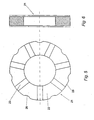
- FIG. 1 a cageless rotor 1 for a DC electric motor is shown.
- the rotor 1 is arranged rotatably in a housing, not shown, with iron yoke and internal permanent magnet coaxial with the shaft 2.
- an existing plastic collector disc 3 is mounted on the cylindrical outer peripheral portion 4 (see also FIGS. 2 to 4 ) Is a sleeve-shaped rotor winding 5 coaxial with the shaft 2 is attached.
- the collector disc 3 has a projecting over the rotor winding 5, substantially cylindrical extension 6, in which the arranged parallel to the shaft axis legs 8 of the collector wires 7 are embedded.
- the collector wires 7 also have a leg 9 arranged perpendicular to the leg 8, which extends radially outwards from the shaft axis. As a result, each collector wire 7 receives an approximate L-shape in side view.
- collector wires 7 are arranged uniformly distributed on the collector disk 3 in this way.
- the parallel legs 8 of the collector wires 7 are embedded in the extension 6 so that they with their top 10 are exposed to the outside, so that appropriate brushes can be placed on them.
- the parallel legs 8 of the collector wires 7 thus form a collector sleeve 11.
- the cross section of the collector wires 7 is substantially trapezoidal, with the longer side facing outwards and defining the outside 10. The shorter side is firmly embedded in the extension 6.
- Each collector wire 7 extends over the extension 6 in a central region 12 of the collector write 3, in which the wires are completely enclosed in plastic. In this center region 12 is also the transition of the collector wires 7 from the parallel leg 8 in the vertical leg 9.
- the collector plate 3 has a cylindrical shoulder 13 with a receiving bore into which a knurled portion 14 of the shaft 2 is pressed. As a result, a rotationally fixed connection between the collector disk 3 and shaft 2 is achieved.
- the radially leading to the outer peripheral portion 4 section 15 of the collector plate 3 has a facing away from the rotor winding 5 front 16 and a pointing in the direction of the rotor winding 5 back 17.
- annular recess 18 is formed, which is arranged coaxially to the shaft axis.
- the cross section of the recess 18 is substantially rectangular.
- the vertical legs 9 extend the collector wires 7, so that the rear side 20 are arranged as contact surfaces in the recess 18.
- the condenser disk 21 is made of a special ceramic and has separate contact surfaces 22. These contact surfaces 22 are achieved by silvering the surface of the capacitor disk 21. The contact surfaces 22 are separated from each other by the free strips 23. The arrangement of the capacitor disk 21 in the recess 18 (see FIG. 1 ) takes place in such a way that the contact surfaces 22 come into contact with the rear side 22 with the correspondingly assigned collector wires 7.
- the capacitor disk 21 is optimally arranged and aligned in the recess 18, ramp-shaped alignment projections 24 are provided on the outer wall 23 of the recess 18 at a uniform spacing.
- the Ausrichtvorsprünge 24 are always located exactly adjacent to the free ends 9 'of the collector wires. 7 As a result, there is additionally a support for the free ends 9 'of the collector wires 7, since an accumulation of material is produced in this region.
- the condenser disk 21 has alignment recesses 26 which are distributed uniformly on its outer circumference 25 to the shape of the alignment projections 24.
- the capacitor plate 21 is inserted into the recess 18 so that the Ausrichtvorsprünge 24 are inserted exactly into the Ausrichtaussparieux 26 in the condenser disk 21.
- the collector plate 3 also has on the front side 16 to the recess 18 open access openings 27 which are configured such that seen from the front side 16 forth the vertical leg 9 and the contact surfaces 22 of the capacitor plate 21 are visible and accessible.
- the access opening 27 extends from the central region 12 radially outward to approximately to the point where the free end 9 'of the collector wires 7 is embedded in the collector plate 3. There remains just so much material that a secure fixation of the free end 9 'remains guaranteed.
- the access opening 27 is slightly enlarged laterally, which brings advantages for the connection technology between capacitor plate 21 and collector plate 7. Between the individual access openings 27 remain spokes 28 which connect the central region 12 with the outer peripheral region 4.
- the fixed connection between the vertical leg 9 of the collector wires 7 and the contact surfaces 22 of the capacitor disk 1 can be done in various ways, e.g. by solder, solder paste or conductive adhesive.
- this connecting aid can be introduced via the access opening 27 from the front side 16 of the collector disk 3. This significantly simplifies the connection technique, since the condenser disk 21 can only be inserted from the rear 17 and then the connection can be made from the front side with a suitable auxiliary substance.
- the capacitor disk 21 can be inserted into the recess 18 in a simple manner and is aligned very easily by the alignment recess 26 together with the alignment projections 24, there is direct contact between the rear side 9 of the collector wires 7 and the contact surfaces 22 of the capacitor disk 21.
- a bonding aid via the access opening 27, a fixed connection between the collector wires 7 and the capacitor disk 21 is then established. This procedure has considerable advantages over hitherto used connection techniques in the prior art, since it is much easier to implement and based on a less expensive construction.
- the capacitor plate 21 is located substantially within the covered by the collector wires diameter range, this connection technology takes only a relatively small space. That is, the free ends 9 'of the collector wires define a diameter that is larger than the outer diameter of the capacitor plate 21. This implies that runners 1 of extremely small diameter can be produced, which in turn results in small diameter electric motors. So far, DC electric motors could not be produced with capacitor disks 21 with diameters of less than 15 mm. The present invention now allows itself to embodiments of such electric motors with a smaller diameter.
- the capacitor plate 21 has the advantage that the life of the DC electric motors with ironless rotor 1 and collector is substantially increased, since it comes to less sparking.
- the main difference is that the shaft 2 extends through the collector plate 3 and thus the extension 6, so that the shaft 2 is also disposed within the collector sleeve 11.
- a storage on the, in FIG. 8 done on the left side shaft approach is the same as the previous embodiment.
Landscapes
- Engineering & Computer Science (AREA)
- Power Engineering (AREA)
- Dc Machiner (AREA)
- Motor Or Generator Current Collectors (AREA)
Claims (13)
- Moteur électrique à courant continu, en particulier de petites dimensions, avec une plaque collectrice (3) qui est montée sur un arbre (2), plusieurs fils collecteurs (7) qui sont tenus par la plaque collectrice (3) et qui sont groupés en un manchon collecteur (11), et une plaque annulaire formant condensateur (21) qui est elle aussi disposée dans la zone de la plaque collectrice (3) et dont la surface de contact (22), associée en conséquence, est reliée électriquement à au moins un fil collecteur (7) correspondant, étant précisé que la plaque formant condensateur (21) est posée directement, avec ses surfaces de contact (22), sur les fils collecteurs (7) et est reliée à ceux-ci,
caractérisé en ce que la plaque collectrice (3) présente un creux annulaire (18) qui est disposé coaxialement par rapport à l'arbre (2) et dans lequel est insérée la plaque formant condensateur (21), étant précisé que les extrémités libres (9') des faisceaux d'un raccordement en étoile qui sont formés par les fils collecteurs (7) individuels sont encastrées dans la plaque collectrice. - Moteur électrique à courant continu selon la revendication 1, caractérisé en ce que les fils collecteurs (7) sont groupés de telle sorte qu'ils forment avec une partie (8) le manchon collecteur (11), et avec une partie suivante le raccordement en étoile, étant précisé que le raccordement en étoile est posé sur la plaque formant condensateur (21).
- Moteur électrique à courant continu selon la revendication 1 ou 2, caractérisé en ce que la plaque formant condensateur (21) est posée sur la face arrière (20) du raccordement en étoile qui est opposée au manchon collecteur (11).
- Moteur électrique à courant continu selon l'une des revendications 1 à 3, caractérisé en ce que les fils collecteurs (7) comportent une branche (8) qui est globalement parallèle à l'arbre (2) et qui fait partie du manchon collecteur (11), et une branche (9) globalement perpendiculaire qui fait partie du raccordement en étoile.
- Moteur électrique à courant continu selon l'une des revendications 1 à 4, caractérisé en ce que le manchon collecteur (11) est disposé sur la face avant (16) de la plaque collectrice (3), et le creux (18) sur la face arrière (17) de la plaque collectrice (3), étant précisé que le raccordement en étoile s'étend dans le creux (18).
- Moteur électrique à courant continu selon l'une des revendications 1 à 5, caractérisé en ce qu'il est prévu sur la face avant (16) de la plaque collectrice (3) des ouvertures d'accès (27) qui coupent le creux (18) pour l'accès aux branches (9) des fils collecteurs (7) qui forment le raccordement en étoile.
- Moteur électrique à courant continu selon la revendication 6, caractérisé en ce qu'il est prévu, associée à chaque fil collecteur (7), une ouverture d'accès individuelle (27) qui est disposée à une certaine distance du bord extérieur (4) du disque collecteur (3).
- Moteur électrique à courant continu selon l'une des revendications 1 à 7, caractérisé en ce qu'il est prévu dans le creux (18) une saillie d'alignement (24) qui pénètre dans un creux d'alignement (26) disposé sur la plaque formant condensateur (21).
- Moteur électrique à courant continu selon la revendication 8, caractérisé en ce que la saillie d'alignement (24) est disposée à un endroit à l'intérieur du creux (18) où la zone d'extrémité libre (9') d'une partie de fil collecteur (9) est fixée au raccordement en étoile par la plaque collectrice (3), et offre un support supplémentaire de la zone d'extrémité (9'), étant précisé que le creux d'alignement (26) est disposé sur la circonférence extérieure (25) de la plaque formant condensateur (21).
- Moteur électrique à courant continu selon la revendication 9, caractérisé en ce qu'il est prévu, associée à chaque zone d'extrémité libre (9') d'une partie de fil collecteur (9) sur le raccordement en étoile, une saillie d'alignement (24), et la plaque formant condensateur (21) présente un nombre correspondant de creux d'alignement (26).
- Moteur électrique à courant continu selon l'une des revendications 1 à 10, caractérisé en ce que la plaque formant collecteur (21) est fabriquée par injection de matière plastique, et les fils collecteurs (7) sont encastrés, au moins par zones, dans la masse de matière plastique.
- Moteur électrique à courant continu selon l'une des revendications 1 à 11, caractérisé en ce que les fils collecteurs (7) sont reliés aux surfaces de contact (22) de la plaque formant condensateur (21) par un agent auxiliaire conducteur, en particulier de l'étain de brasage, de la pâte de brasage et/ou une colle conductrice.
- Moteur électrique à courant continu selon l'une des revendications 6 à 12, caractérisé en ce que l'ouverture d'accès (27) est un peu agrandie latéralement.
Applications Claiming Priority (2)
| Application Number | Priority Date | Filing Date | Title |
|---|---|---|---|
| DE19740551 | 1997-09-15 | ||
| DE19740551A DE19740551A1 (de) | 1997-09-15 | 1997-09-15 | Gleichstromelektromotor |
Publications (2)
| Publication Number | Publication Date |
|---|---|
| EP0902524A1 EP0902524A1 (fr) | 1999-03-17 |
| EP0902524B1 true EP0902524B1 (fr) | 2011-10-12 |
Family
ID=7842420
Family Applications (1)
| Application Number | Title | Priority Date | Filing Date |
|---|---|---|---|
| EP98115353A Expired - Lifetime EP0902524B1 (fr) | 1997-09-15 | 1998-08-14 | Moteur à courant continu |
Country Status (5)
| Country | Link |
|---|---|
| US (1) | US6144133A (fr) |
| EP (1) | EP0902524B1 (fr) |
| JP (1) | JPH11313467A (fr) |
| AT (1) | ATE528842T1 (fr) |
| DE (1) | DE19740551A1 (fr) |
Families Citing this family (10)
| Publication number | Priority date | Publication date | Assignee | Title |
|---|---|---|---|---|
| DE10021392C2 (de) * | 2000-05-03 | 2002-09-12 | Interelectric Ag Holding Sachs | Glockenankerelektromotor |
| DE10144040B4 (de) * | 2001-09-07 | 2007-06-14 | Sintertechnik Gmbh | Kommutator für Elektrokleinmotor |
| EP1294080A3 (fr) * | 2001-09-07 | 2003-10-15 | Sintertechnik GmbH | Commutateur pour petit moteur électrique |
| DE10250142B4 (de) * | 2002-10-28 | 2013-06-27 | Maxon Motor Ag | Masseschlussfester Gleichstromelektromotor |
| US6975058B2 (en) * | 2004-03-17 | 2005-12-13 | Sintertechnik Gmbh | Commutator arrangement for a small electric motor |
| DE102006021696B4 (de) * | 2006-05-10 | 2014-04-24 | Kolektor Group D.O.O. | Verfahren zur Herstellung eines Rotors einer dynamoelektrischen Maschine sowie Rotor einer dynamoelektrischen Maschine |
| DE102010049524B4 (de) | 2010-10-25 | 2016-07-14 | Maxon Motor Ag | Gleichstromelektromotor mit flexiblem Rotoraufbau sowie Verfahren zu dessen Herstellung |
| CN102386720A (zh) * | 2011-11-18 | 2012-03-21 | 深圳市仓兴达科技有限公司 | 一种带电容的转子支架和空心杯永磁直流微电机 |
| DE102013206925A1 (de) * | 2013-04-17 | 2014-10-23 | Robert Bosch Gmbh | Elektrische Maschine mit einem Entstörbauelement sowie Verfahren zur Montage eines solchen Kondensatorbauelements |
| JP6779818B2 (ja) * | 2017-03-22 | 2020-11-04 | シチズン時計株式会社 | 直流モータ用整流子及びその製造方法 |
Citations (1)
| Publication number | Priority date | Publication date | Assignee | Title |
|---|---|---|---|---|
| US3594598A (en) * | 1968-10-23 | 1971-07-20 | Buehler Gmbh Nachf Geb | Spark-suppressing commutator arrangement for electric motor |
Family Cites Families (10)
| Publication number | Priority date | Publication date | Assignee | Title |
|---|---|---|---|---|
| JPS4971402A (fr) * | 1972-11-15 | 1974-07-10 | ||
| JPS53147904A (en) * | 1977-05-31 | 1978-12-23 | Matsushita Electric Works Ltd | Spark absorbing device for minimotor |
| JPS5918944B2 (ja) * | 1978-06-12 | 1984-05-01 | マブチモ−タ−株式会社 | 小型モ−タ |
| JPS5541139A (en) * | 1978-09-12 | 1980-03-22 | Matsushita Electric Ind Co Ltd | Coreless motor |
| JPS5634200A (en) * | 1979-08-29 | 1981-04-06 | Fujitsu Ltd | Error correction system |
| JPS57148560A (en) * | 1981-03-09 | 1982-09-13 | Matsushita Electric Works Ltd | Rotor for commutator motor |
| DD205586A1 (de) | 1982-03-31 | 1983-12-28 | Elektromasch Forsch Entw | Anordnung zur schaltspannungsbedaempfung an kommutatoren von kleinmaschinen |
| JP2510549Y2 (ja) * | 1991-12-17 | 1996-09-11 | マブチモーター株式会社 | 小型モ―タ |
| US5473212A (en) * | 1993-10-13 | 1995-12-05 | Buehler Products, Inc. | Varistor disk assembly |
| GB9423689D0 (en) * | 1994-11-24 | 1995-01-11 | Johnson Electric Sa | A rotor for an electric motor |
-
1997
- 1997-09-15 DE DE19740551A patent/DE19740551A1/de not_active Ceased
-
1998
- 1998-08-14 AT AT98115353T patent/ATE528842T1/de active
- 1998-08-14 EP EP98115353A patent/EP0902524B1/fr not_active Expired - Lifetime
- 1998-09-09 US US09/149,971 patent/US6144133A/en not_active Expired - Fee Related
- 1998-09-16 JP JP10300276A patent/JPH11313467A/ja active Pending
Patent Citations (1)
| Publication number | Priority date | Publication date | Assignee | Title |
|---|---|---|---|---|
| US3594598A (en) * | 1968-10-23 | 1971-07-20 | Buehler Gmbh Nachf Geb | Spark-suppressing commutator arrangement for electric motor |
Also Published As
| Publication number | Publication date |
|---|---|
| US6144133A (en) | 2000-11-07 |
| DE19740551A1 (de) | 1999-03-18 |
| EP0902524A1 (fr) | 1999-03-17 |
| JPH11313467A (ja) | 1999-11-09 |
| ATE528842T1 (de) | 2011-10-15 |
Similar Documents
| Publication | Publication Date | Title |
|---|---|---|
| DE3912873C2 (fr) | ||
| EP0444044B1 (fr) | Systeme de bague collectrice | |
| EP0902524B1 (fr) | Moteur à courant continu | |
| DE69806179T2 (de) | Drahtführungsanordnung für den rotor einer elektrischen maschine | |
| WO2008019932A1 (fr) | Rotor pour moteur électrique | |
| DE3439831C2 (de) | Bürstenträger für den stirnseitigen Kollektor eines Elektromotors | |
| DE4447880B4 (de) | Radialmagnetmotor | |
| EP1372249A2 (fr) | Machine à flux transversal et plus particulièrement machine unipolaire à flux transversal | |
| DE9200625U1 (de) | Anschlußdeckel für Elektrokraftstoffpumpe | |
| DE10044478C2 (de) | Schwingungsaufnehmer bzw. Isolierscheibe für einen Schwingungsaufnehmer | |
| DE19748150B4 (de) | Spindelmotor mit Kontaktierung | |
| DE3308946C2 (fr) | ||
| WO1995020258A1 (fr) | Cage servant a maintenir des aimants permanents dans le stator d'un moteur electrique | |
| EP2409383B1 (fr) | Module d'induit et machine électrique avec un module d'induit | |
| DE2458358A1 (de) | Oszillator-anordnung | |
| DE7540211U (de) | Ring mit zwei Kollektorspuren für eine elektrische Maschine | |
| DE102016101878A1 (de) | Elektromotor und Aktor umfassend einen derartigen Elektromotor, sowie Verfahren zur Herstellung eines solchen Aktors | |
| WO2010102753A1 (fr) | Stator destiné à un moteur électrique, procédé de fabrication dudit stator, et moteur électrique équipé d'un tel stator | |
| DE69402943T2 (de) | Zündkerzenverbindungsglied | |
| EP1537644B1 (fr) | Logement pour fixer un composant sur un porte-balais | |
| DE102023134101B4 (de) | Stromableitelement | |
| DE1272414B (de) | Steckverbinder fuer elektrische Leitungen | |
| DE102019122603A1 (de) | Rotorvorrichtung und Statorvorrichtung für einen flachen bürstenlosen elektrischen Motor sowie flacher, bürstenloser elektrischer Motor für ein Dachsystem eines Automobils | |
| EP1503483B1 (fr) | Procédé pour fixer une bobine d'anti-parasitage et dispositif contenant une telle bobine | |
| DE102022004460A1 (de) | Erdungsvorrichtung |
Legal Events
| Date | Code | Title | Description |
|---|---|---|---|
| PUAI | Public reference made under article 153(3) epc to a published international application that has entered the european phase |
Free format text: ORIGINAL CODE: 0009012 |
|
| AK | Designated contracting states |
Kind code of ref document: A1 Designated state(s): AT CH DE FR GB IT LI NL |
|
| AX | Request for extension of the european patent |
Free format text: AL;LT;LV;MK;RO;SI |
|
| 17P | Request for examination filed |
Effective date: 19990913 |
|
| AKX | Designation fees paid |
Free format text: AT CH DE FR GB IT LI NL |
|
| 17Q | First examination report despatched |
Effective date: 20061103 |
|
| GRAP | Despatch of communication of intention to grant a patent |
Free format text: ORIGINAL CODE: EPIDOSNIGR1 |
|
| GRAS | Grant fee paid |
Free format text: ORIGINAL CODE: EPIDOSNIGR3 |
|
| GRAA | (expected) grant |
Free format text: ORIGINAL CODE: 0009210 |
|
| AK | Designated contracting states |
Kind code of ref document: B1 Designated state(s): AT CH DE FR GB IT LI NL |
|
| REG | Reference to a national code |
Ref country code: GB Ref legal event code: FG4D Free format text: NOT ENGLISH |
|
| REG | Reference to a national code |
Ref country code: CH Ref legal event code: NV Representative=s name: PATENTANWALTSBUERO JEAN HUNZIKER AG Ref country code: CH Ref legal event code: EP |
|
| REG | Reference to a national code |
Ref country code: DE Ref legal event code: R096 Ref document number: 59814503 Country of ref document: DE Effective date: 20111208 |
|
| REG | Reference to a national code |
Ref country code: NL Ref legal event code: VDEP Effective date: 20111012 |
|
| PG25 | Lapsed in a contracting state [announced via postgrant information from national office to epo] |
Ref country code: NL Free format text: LAPSE BECAUSE OF FAILURE TO SUBMIT A TRANSLATION OF THE DESCRIPTION OR TO PAY THE FEE WITHIN THE PRESCRIBED TIME-LIMIT Effective date: 20111012 |
|
| PLBE | No opposition filed within time limit |
Free format text: ORIGINAL CODE: 0009261 |
|
| STAA | Information on the status of an ep patent application or granted ep patent |
Free format text: STATUS: NO OPPOSITION FILED WITHIN TIME LIMIT |
|
| PG25 | Lapsed in a contracting state [announced via postgrant information from national office to epo] |
Ref country code: IT Free format text: LAPSE BECAUSE OF FAILURE TO SUBMIT A TRANSLATION OF THE DESCRIPTION OR TO PAY THE FEE WITHIN THE PRESCRIBED TIME-LIMIT Effective date: 20111012 |
|
| 26N | No opposition filed |
Effective date: 20120713 |
|
| REG | Reference to a national code |
Ref country code: DE Ref legal event code: R097 Ref document number: 59814503 Country of ref document: DE Effective date: 20120713 |
|
| REG | Reference to a national code |
Ref country code: AT Ref legal event code: MM01 Ref document number: 528842 Country of ref document: AT Kind code of ref document: T Effective date: 20120831 |
|
| PG25 | Lapsed in a contracting state [announced via postgrant information from national office to epo] |
Ref country code: AT Free format text: LAPSE BECAUSE OF NON-PAYMENT OF DUE FEES Effective date: 20120831 |
|
| REG | Reference to a national code |
Ref country code: FR Ref legal event code: PLFP Year of fee payment: 19 |
|
| REG | Reference to a national code |
Ref country code: FR Ref legal event code: PLFP Year of fee payment: 20 |
|
| PGFP | Annual fee paid to national office [announced via postgrant information from national office to epo] |
Ref country code: FR Payment date: 20170821 Year of fee payment: 20 Ref country code: GB Payment date: 20170821 Year of fee payment: 20 Ref country code: DE Payment date: 20170828 Year of fee payment: 20 Ref country code: CH Payment date: 20170817 Year of fee payment: 20 |
|
| REG | Reference to a national code |
Ref country code: DE Ref legal event code: R071 Ref document number: 59814503 Country of ref document: DE |
|
| REG | Reference to a national code |
Ref country code: CH Ref legal event code: PL |
|
| REG | Reference to a national code |
Ref country code: GB Ref legal event code: PE20 Expiry date: 20180813 |
|
| PG25 | Lapsed in a contracting state [announced via postgrant information from national office to epo] |
Ref country code: GB Free format text: LAPSE BECAUSE OF EXPIRATION OF PROTECTION Effective date: 20180813 |