EP0903064B1 - Gehäuse - Google Patents
Gehäuse Download PDFInfo
- Publication number
- EP0903064B1 EP0903064B1 EP97925976A EP97925976A EP0903064B1 EP 0903064 B1 EP0903064 B1 EP 0903064B1 EP 97925976 A EP97925976 A EP 97925976A EP 97925976 A EP97925976 A EP 97925976A EP 0903064 B1 EP0903064 B1 EP 0903064B1
- Authority
- EP
- European Patent Office
- Prior art keywords
- emc
- housing
- spring elements
- front panel
- housing according
- Prior art date
- Legal status (The legal status is an assumption and is not a legal conclusion. Google has not performed a legal analysis and makes no representation as to the accuracy of the status listed.)
- Expired - Lifetime
Links
- 238000007789 sealing Methods 0.000 claims description 27
- 238000010276 construction Methods 0.000 claims description 3
- 229920003023 plastic Polymers 0.000 claims description 3
- 239000004033 plastic Substances 0.000 claims description 3
- 229910000831 Steel Inorganic materials 0.000 claims 1
- 239000010959 steel Substances 0.000 claims 1
- 230000000712 assembly Effects 0.000 description 2
- 238000000429 assembly Methods 0.000 description 2
- 230000000694 effects Effects 0.000 description 2
- 238000004519 manufacturing process Methods 0.000 description 2
- 239000000463 material Substances 0.000 description 2
- 238000005452 bending Methods 0.000 description 1
- 230000015572 biosynthetic process Effects 0.000 description 1
- 210000000078 claw Anatomy 0.000 description 1
- 239000004020 conductor Substances 0.000 description 1
- 230000001419 dependent effect Effects 0.000 description 1
- 230000000994 depressogenic effect Effects 0.000 description 1
- 238000009434 installation Methods 0.000 description 1
- 238000000034 method Methods 0.000 description 1
- 238000004080 punching Methods 0.000 description 1
- 229910001220 stainless steel Inorganic materials 0.000 description 1
- 239000010935 stainless steel Substances 0.000 description 1
Images

Classifications
-
- H—ELECTRICITY
- H05—ELECTRIC TECHNIQUES NOT OTHERWISE PROVIDED FOR
- H05K—PRINTED CIRCUITS; CASINGS OR CONSTRUCTIONAL DETAILS OF ELECTRIC APPARATUS; MANUFACTURE OF ASSEMBLAGES OF ELECTRICAL COMPONENTS
- H05K9/00—Screening of apparatus or components against electric or magnetic fields
- H05K9/0007—Casings
- H05K9/0015—Gaskets or seals
- H05K9/0016—Gaskets or seals having a spring contact
Definitions
- the invention relates to a housing for receiving electrical and electronic assemblies according to the preamble of claim 1; (see DE-A-3 444 668).
- Known housings in particular desktop housings, consist of U-shaped housing shells and a front and back plate.
- the housing shells are usually in the range of their lateral longitudinal edges with fastening screws together connected.
- the front panel and / or the back panel in grooves which are in the area of an end face and / or a rear opening in the housing shells are trained.
- a front panel attachment or back plate is done with fastening screws or locking bolts that are in plug-in profiles inside the housing secured with threaded strips.
- the invention has for its object to provide a housing construction which enables inexpensive fastening of a front panel and / or a rear panel and at the same time ensures EMC shielding and IP tightness in a particularly efficient manner.
- the invention is based on the basic idea of a front panel screwless in a front opening of a Housing, in particular one consisting of two housing shells Small case to fix.
- the screwless fastening the front panel is made with inclusion and with the help of a combination of an elastic sealing profile and conductive spring elements, which both the attachment the front plate on the housing as well as an EMC shield and IP sealing guaranteed.
- the conductive spring elements which are designed like a hook or clip, as a EMC spring band can be arranged, which in different Dimensions cut to length and used can.
- EMC spring elements in particular as a spring band, be attached to the longitudinal edges of the front panel can and from an elastic seal arranged above it, which in particular is designed as a sealing frame is kept, is a particularly quick and uncomplicated A front panel can be attached.
- IP seal Sealing frame formed from a sealing profile, which on Cut length and can then be connected.
- the Sealing profile and the EMC spring elements are such trained that a secure connector on the edges the front panel is accessible.
- a clamping bar which almost at right angles from the U-shaped attachment area protrudes and is directed into the housing, has as a Locking or clamping element on a stamping or punching, which protrudes towards the housing.
- Sealing and shielding arrangement provided Front plate on a circumferential retaining web of the housing opening jammed or locked.
- the EMC spring elements and the holding bridge as well as that Sealing profile dimensioned such that the required Clamping effect is achievable.
- the sealing profile or the sealing frame is expediently which is essential for mounting the EMC spring elements contributes from a plastic material with such a Made elasticity that the clamping effect and a secure mounting of a cover plate are guaranteed.
- a constructive design of the sealing profile with a Outer leg which is the outer area of the EMC spring elements and the area between an edge area of the Covered housing and the front panel, secures at the same time an aesthetically advantageous view of the housing side.
- the solution according to the invention is based on the screwless Fixing a front panel in a small housing described the invention is not for this application limited.
- the back plate can be one housing consisting of housing shells fastened without screws become.
- the invention is basically for attachment of plates or plate-shaped components.
- openings in the side walls or in a top or bottom surface of a housing with screwless attachable plates are provided.
- Arrangement of spring elements and elastic Sealing profile interacting retaining webs or Mounting flanges can e.g. additionally in scope the opening.
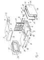
- FIG. 1 shows a table housing as a housing 2, which has two U-shaped half shells as housing shells 3, 5 and a front plate 7 and a rear plate 11 having.
- the housing shells 3, 5 are made from a one-piece blank manufactured and have outward-facing bends 13, 15 on which of the connection of the housing shells 3, 5 serve. To cover the folded edges 13, 15 side strips 8 are provided, which in Area of a front opening 17 and a rear Opening 27 with in particular pluggable corner elements 18 can be completed.
- U-shaped housing half-shells 3, 5 have corner slopes 4 on, in the area of which the circumferential retaining web 6 is mitred cut and welded, for example.
- To the Installation of components and assemblies are further construction elements provided, of which only by way of example a mounting side wall 29 and a mounting plate 28 are shown.
- the interior of the retaining web 6 directed from a section Representation of a front area in Figure 2 out.
- the retaining web 6 then runs almost perpendicular to the housing 2 and to an edge region 9, which, as a 180 ° bend, is particularly stable Edge area forms.
- Figure 2 shows an enlargement of the screwless attachment the front plate 7 in the region of the holding web 6 and of the housing edge area 9.
- This screwless fastening takes place in cooperation with a combination of an appropriately trained sealing frame 20, which is made of an elastic plastic profile is formed, and spring elements 10 made of a conductive Material, which in particular as a cutable spring band 25 (see Fig. 1) are arranged.
- an EMC spring band 25 in the required Length plugged onto edge areas 19 of the front plate 7.
- at least longitudinal edges 19 of the front plate 7 each be provided with a spring band 25.
- the sealing frame 20 is applied, which is dimensioned such that the spring elements 10 largely in a plug-on area 12 covered and thereby held.
- the front plate 7 thus completed is then in the front opening 17 depressed, with an inner leg 24 and a connecting leg 22 of the sealing frame 20th elastically deformed, in particular compressed.
- the fixation is achieved in particular with a clamping web 14, which is approximately at right angles from the plug-on area 12 EMC spring elements 10 and directed into the interior of the housing is.
- linear Clamping web 14 has two orientations directed towards the housing or cutouts 16, in the present example approximately triangular Claws which lock behind the retaining bridge 6 and in this way the front panel 7 with the sealing frame 20th and EMC spring elements 10 hold non-positively.
- the sealing frame 20 which in the training shown in Fig. 2 about a T-shaped cross section with an almost has horizontal inner leg 24, overlaps with a Outer leg 26 essentially the plug-on area 12 of the EMC spring elements 10 and secured an IP seal the housing in the area of the front panel 7 and the front Housing edge 9.
- the spring elements 10 are as an EMC spring band 25 trained and over a jetty or investment area 31, which is almost horizontal and continuous is formed and in the fixed state on an inner surface the front plate 7 rests, connected to each other.
- a stainless steel one is particularly advantageous EMC spring band, which is designed in the manner of a double hook is and according to Figure 2 on the edges 19 of a front panel 7 attachable and on a holding bridge 6 one Housing 2 can be locked or clamped.
- the EMC spring elements in a front plate or in any other cover plate be integrated into a housing opening. Training the cover plates with integrated EMC spring elements for example in a stamping and bending process. It a suitably designed sealing frame is then sufficient, which interacts with clamping elements of the EMC spring elements, a screwless fastening of a front panel to ensure.
Landscapes
- Engineering & Computer Science (AREA)
- Microelectronics & Electronic Packaging (AREA)
- Casings For Electric Apparatus (AREA)
- Mounting Of Printed Circuit Boards And The Like (AREA)
- Glass Compositions (AREA)
Description
- Fig. 1
- ein erfindungsgemäßes Gehäuse in einer Explosionsdarstellung;
- Fig. 2
- einen horizontalen Schnitt durch einen frontseitigen Bereich eines erfindungsgemäßen Gehäuses mit schraublos befestigter Frontplatte und
- Fig. 3
- eine perspektivische Darstellung eines EMV-Federbandes mit Federelementen.
Claims (14)
- Gehäuse zur Aufnahme von elektrischen und elektronischen Baugruppen,
mit einer in einer frontseitigen Öffnung (17) angeordneten Frontplatte (7),
wobei die Frontplatte (7) an einem Haltesteg ( 6) des Gehäuses (2) angeordnet ist, welcher die frontseitige Öffnung (17) in einer zurückgesetzten Anordnung umgibt und in die frontseitige Öffnung (17) ragt, und dadurch gekennzeichnet,
daß eine Anordnung aus leitfähigen Federelementen (10) und einer elastischen Dichtung (20) vorgesehen ist, welche die Frontplatte (7) schraublos sowie EMV-abgeschirmt und IP-dicht hält. - Gehäuse nach Anspruch 1,
dadurch gekennzeichnet,
daß die leitfähigen Federelemente (10) als haken- oder klammerartige EMV-Federelemente (10) ausgebildet und auf Kanten (19) der Frontplatte (7) aufsteckbar sind. - Gehäuse nach Anspruch 1 oder 2,
dadurch gekennzeichnet,
daß die elastische Dichtung (20) als ein IP-Dichtrahmen (20) ausgebildet ist, welcher unter Halterung der kantenseitig angeordneten EMV-Federelemente (10) auf die Frontplatte (7) aufsteckbar ist. - Gehäuse nach einem der vorhergehenden Ansprüche,
dadurch gekennzeichnet,
daß die EMV-Federelemente (10) doppelhakenartig ausgebildet sind, mit einem U-förmigen Aufsteckbereich (12) auf die Kanten (19) der Frontplatte (7) aufsteckbar und mit einem Klemmsteg (14), welcher in das Gehäuse (2) gerichtet ist, an dem Haltesteg (6) des Gehäuses (2) fixierbar ist. - Gehäuse nach einem der vorhergehenden Ansprüche,
dadurch gekennzeichnet,
daß die EMV-Federelemente (10) Rast- oder Klemmelemente, insbesondere Ausprägungen oder Ausstanzungen (16) aufweisen, welche nach einem Eindrücken der Frontplatte (7) mit aufgesteckten EMV-Federelementen (10) und IP-Dichtrahmen (20) hinter dem Haltesteg (6) des Gehäuses (2) einrasten. - Gehäuse nach einem der vorhergehenden Ansprüche,
dadurch gekennzeichnet,
daß der Dichtrahmen (20) einen Außenschenkel (26) aufweist, welcher den Aufsteckbereich (12) der EMV-Federelemente (10) abdeckt und insbesondere bis auf die Frontplatte (7) sowie bis zu einer Gehäusekante (9) reicht. - Gehäuse nach einem der vorhergehenden Ansprüche,
dadurch gekennzeichnet,
daß der Dichtrahmen (20) mit dem Außenschenkel (26), einem Verbindungsschenkel (22) und einem Innenschenkel (24) zwischen der Frontplatte (7), welche mit EMV-Federelementen (10) versehen ist, und dem Gehäuse (2) angeordnet ist. - Gehäuse nach einem der vorhergehenden Ansprüche,
dadurch gekennzeichnet,
daß der Dichtrahmen (20) aus einem elastischen Kunststoffprofil durch Ablängen und Verbinden gebildet ist. - Gehäuse nach einem der vorhergehenden Ansprüche,
dadurch gekennzeichnet,
daß bei einer fixierten Frontplatte (7) der Verbindungsschenkel (22) und der Innenschenkel (24) des Dichtrahmens (20), welche etwa rechtwinklig zueinander ausgebildet sind, elastisch verformbar an dem Haltesteg (6) und an dem Kantenbereich (9) des Gehäuses (2) anliegen. - Gehäuse nach einem der vorhergehenden Ansprüche,
dadurch gekennzeichnet,
daß es aus zwei U-förmigen Halbschalen (3, 5) gebilet ist und eine Rückplatte (11), welche in einer rückseitigen Öffnung (27) angeordnet ist, mit einer Anordnung aus EMV-Federelementen (10) und einem IP-Dichtrahmen (20) schraublos gehalten ist. - Gehäuse nach einem der vorhergehenden Ansprüche,
dadurch gekennzeichnet,
daß die EMV-Federelemente (10) als ein EMV-Federband (25) ausgebildet und/oder aus Edelstahl gefertigt sind. - Gehäuse nach einem der vorhergehenden Ansprüche,
dadurch gekennzeichnet,
daß die EMV-Federelemente (10) über einen Anlagebereich oder einen Anlagesteg (31), welcher zwischen dem Aufsteckbereich (12) und dem Klemmsteg (14) als eine nahezu durchgehende Fläche ausgebildet ist, zu einem Federband (25) verbunden sind. - Gehäuse nach Anspruch 1,
dadurch gekennzeichnet,
daß EMV-Federelemente (10) oder ein EMV-Federband (25) in die Frontplatte (7) integriert sind und daß die Frontplatte (7) mit einem IP-Dichtrahmen (20) in die frontseitige Öffnung (17) schraublos einklemmbar oder verrastbar ist. - Gehäuse nach Anpruch 1 oder 13,
dadurch gekennzeichnet,
daß Seitenplatten und/oder Deck- und/oder Bodenplatten mit einer Anordnung aus EMV-Federelementen (10) und einem IP-Dichtrahmen (20) schraublos in Öffnungen in Seitenwänden, einer Deckfläche und/oder einer Bodenfläche fixierbar sind.
Applications Claiming Priority (3)
| Application Number | Priority Date | Filing Date | Title |
|---|---|---|---|
| DE29609873U | 1996-06-04 | ||
| DE29609873U DE29609873U1 (de) | 1996-06-04 | 1996-06-04 | Gehäuse |
| PCT/EP1997/002857 WO1997047166A1 (de) | 1996-06-04 | 1997-06-02 | Gehäuse |
Publications (2)
| Publication Number | Publication Date |
|---|---|
| EP0903064A1 EP0903064A1 (de) | 1999-03-24 |
| EP0903064B1 true EP0903064B1 (de) | 2000-10-18 |
Family
ID=8024770
Family Applications (1)
| Application Number | Title | Priority Date | Filing Date |
|---|---|---|---|
| EP97925976A Expired - Lifetime EP0903064B1 (de) | 1996-06-04 | 1997-06-02 | Gehäuse |
Country Status (3)
| Country | Link |
|---|---|
| EP (1) | EP0903064B1 (de) |
| DE (2) | DE29609873U1 (de) |
| WO (1) | WO1997047166A1 (de) |
Families Citing this family (3)
| Publication number | Priority date | Publication date | Assignee | Title |
|---|---|---|---|---|
| DE10111646B4 (de) * | 2000-05-16 | 2008-10-02 | Heidelberger Druckmaschinen Ag | Abgeschirmtes Schaltschrankgehäuse |
| EP2954908B1 (de) | 2013-04-01 | 2018-08-08 | Terumo Kabushiki Kaisha | Beschichtungszusammensetzung und medizinische vorrichtung |
| DE102017101414A1 (de) * | 2017-01-25 | 2018-07-26 | Sma Solar Technology Ag | Emv abschirmende dichtung und elektrisches oder elektronisches gerät mit einer dichtung |
Family Cites Families (5)
| Publication number | Priority date | Publication date | Assignee | Title |
|---|---|---|---|---|
| FR1089701A (fr) * | 1952-12-17 | 1955-03-21 | Ft Products Ltd | Attache |
| US3862535A (en) * | 1971-07-27 | 1975-01-28 | George J Byssing | Clip for non progressive wall construction |
| DE3444668A1 (de) * | 1984-12-07 | 1986-06-12 | Friedrich Merk-Telefonbau GmbH, 8000 München | Gehaeuse, insbesondere fuer anzeigevorrichtungen |
| DE3734564A1 (de) * | 1987-10-13 | 1989-04-27 | Rose Elektrotech Gmbh | Gehaeuse fuer die aufnahme elektrischer und elektronischer bauteile |
| DE8805804U1 (de) * | 1988-05-02 | 1988-07-14 | Schneider, Wolfgang, 4952 Porta Westfalica | Gehäuse für Steuergeräte, -tafeln o.dgl. |
-
1996
- 1996-06-04 DE DE29609873U patent/DE29609873U1/de not_active Expired - Lifetime
-
1997
- 1997-06-02 DE DE59702503T patent/DE59702503D1/de not_active Expired - Fee Related
- 1997-06-02 EP EP97925976A patent/EP0903064B1/de not_active Expired - Lifetime
- 1997-06-02 WO PCT/EP1997/002857 patent/WO1997047166A1/de not_active Ceased
Also Published As
| Publication number | Publication date |
|---|---|
| DE59702503D1 (de) | 2000-11-23 |
| EP0903064A1 (de) | 1999-03-24 |
| WO1997047166A1 (de) | 1997-12-11 |
| DE29609873U1 (de) | 1996-08-22 |
Similar Documents
| Publication | Publication Date | Title |
|---|---|---|
| EP1152506B1 (de) | Rahmengestell | |
| DE878126C (de) | Blechklammer zur behelfsmaessigen Anbringung von Befestigungs-elementen | |
| DE29623551U1 (de) | Schaltschrank | |
| EP0135845A2 (de) | Vorrichtung zur Befestigung eines zwei im Abstandhintereinander angeordnete Tragflansche aufweisenden Gerätes | |
| DE2756248A1 (de) | Klammer zur halterung von leisten, insbesondere zierleisten | |
| EP1072179B1 (de) | Baugruppenträger | |
| DE3442550C1 (de) | Anschlußschuh für C-Blechprofile | |
| DE3529059C2 (de) | Endklammer zur seitlichen Sicherung von Installationsblöcken auf einer symmetrischen Profilschiene | |
| EP3727088B1 (de) | Schubladenseitenwand | |
| DE2852829A1 (de) | Schnellmontagesockel aus kunststoff | |
| EP0139980A2 (de) | Kabelschelle | |
| EP0903063B1 (de) | Gehäuse | |
| DE29609873U1 (de) | Gehäuse | |
| EP1780345B1 (de) | Verbinder für rinnenförmige Profilstäbe und Verbindungsanordnung | |
| DE10216430C1 (de) | Befestigungsanordnung zur Verbindung von Gehäuse- und Verkleidungsteilen | |
| DE69303366T2 (de) | Elektromagnetische abschirmungsvorrichtung | |
| DE4318828C2 (de) | Einbaugerät, insbesondere Einbauspüle | |
| DE3248124A1 (de) | Elektrisches installationsgeraet mit einer vorrichtung zur seiner halterung auf zwei in einem abstand parallel zueinander verlaufenden profiltragschienen, insbesondere von hutprofilschienen | |
| DE29719220U1 (de) | Gehäuse für elektronische Baugruppen | |
| DE19725427C2 (de) | Solarmodulmontagevorrichtung | |
| DE19601614C1 (de) | Vorrichtung zum elektrisch leitenden Verbinden des Rahmengestelles oder des Schrankkorpus eines Schaltschrankes mit der Türe | |
| EP1593786B1 (de) | Befestigungsvorrichtung für Geräteeinsätze in Arbeitsplatten | |
| EP0598350B1 (de) | Verbindungsanordnung zur Bildung einer Gehäusewand mit in Strangpresstechnik hergestellten Wandelementen | |
| DE102005006004B4 (de) | Gehäusedichtung | |
| DE29806897U1 (de) | Baugruppenträger |
Legal Events
| Date | Code | Title | Description |
|---|---|---|---|
| PUAI | Public reference made under article 153(3) epc to a published international application that has entered the european phase |
Free format text: ORIGINAL CODE: 0009012 |
|
| 17P | Request for examination filed |
Effective date: 19981001 |
|
| AK | Designated contracting states |
Kind code of ref document: A1 Designated state(s): DE FR GB |
|
| GRAG | Despatch of communication of intention to grant |
Free format text: ORIGINAL CODE: EPIDOS AGRA |
|
| GRAG | Despatch of communication of intention to grant |
Free format text: ORIGINAL CODE: EPIDOS AGRA |
|
| GRAH | Despatch of communication of intention to grant a patent |
Free format text: ORIGINAL CODE: EPIDOS IGRA |
|
| 17Q | First examination report despatched |
Effective date: 20000114 |
|
| GRAH | Despatch of communication of intention to grant a patent |
Free format text: ORIGINAL CODE: EPIDOS IGRA |
|
| GRAA | (expected) grant |
Free format text: ORIGINAL CODE: 0009210 |
|
| AK | Designated contracting states |
Kind code of ref document: B1 Designated state(s): DE FR GB |
|
| PG25 | Lapsed in a contracting state [announced via postgrant information from national office to epo] |
Ref country code: GB Free format text: LAPSE BECAUSE OF FAILURE TO SUBMIT A TRANSLATION OF THE DESCRIPTION OR TO PAY THE FEE WITHIN THE PRESCRIBED TIME-LIMIT Effective date: 20001018 Ref country code: FR Free format text: LAPSE BECAUSE OF FAILURE TO SUBMIT A TRANSLATION OF THE DESCRIPTION OR TO PAY THE FEE WITHIN THE PRESCRIBED TIME-LIMIT Effective date: 20001018 |
|
| REF | Corresponds to: |
Ref document number: 59702503 Country of ref document: DE Date of ref document: 20001123 |
|
| EN | Fr: translation not filed | ||
| GBV | Gb: ep patent (uk) treated as always having been void in accordance with gb section 77(7)/1977 [no translation filed] |
Effective date: 20001018 |
|
| PGFP | Annual fee paid to national office [announced via postgrant information from national office to epo] |
Ref country code: DE Payment date: 20010629 Year of fee payment: 5 |
|
| PLBE | No opposition filed within time limit |
Free format text: ORIGINAL CODE: 0009261 |
|
| STAA | Information on the status of an ep patent application or granted ep patent |
Free format text: STATUS: NO OPPOSITION FILED WITHIN TIME LIMIT |
|
| 26N | No opposition filed | ||
| PG25 | Lapsed in a contracting state [announced via postgrant information from national office to epo] |
Ref country code: DE Free format text: LAPSE BECAUSE OF NON-PAYMENT OF DUE FEES Effective date: 20030101 |