EP0903093A2 - An element for seating or lying - Google Patents
An element for seating or lying Download PDFInfo
- Publication number
- EP0903093A2 EP0903093A2 EP98115493A EP98115493A EP0903093A2 EP 0903093 A2 EP0903093 A2 EP 0903093A2 EP 98115493 A EP98115493 A EP 98115493A EP 98115493 A EP98115493 A EP 98115493A EP 0903093 A2 EP0903093 A2 EP 0903093A2
- Authority
- EP
- European Patent Office
- Prior art keywords
- lying
- band
- element according
- elastic part
- length
- Prior art date
- Legal status (The legal status is an assumption and is not a legal conclusion. Google has not performed a legal analysis and makes no representation as to the accuracy of the status listed.)
- Withdrawn
Links
- 238000010276 construction Methods 0.000 description 2
- 230000035876 healing Effects 0.000 description 2
- 241001122767 Theaceae Species 0.000 description 1
- 230000037237 body shape Effects 0.000 description 1
- 230000001419 dependent effect Effects 0.000 description 1
- 239000004744 fabric Substances 0.000 description 1
- 230000002349 favourable effect Effects 0.000 description 1
- 210000003041 ligament Anatomy 0.000 description 1
- 239000000463 material Substances 0.000 description 1
- 230000001105 regulatory effect Effects 0.000 description 1
- 230000000284 resting effect Effects 0.000 description 1
- 238000007665 sagging Methods 0.000 description 1
- 239000004576 sand Substances 0.000 description 1
Images

Classifications
-
- A—HUMAN NECESSITIES
- A47—FURNITURE; DOMESTIC ARTICLES OR APPLIANCES; COFFEE MILLS; SPICE MILLS; SUCTION CLEANERS IN GENERAL
- A47C—CHAIRS; SOFAS; BEDS
- A47C7/00—Parts, details, or accessories of chairs or stools
- A47C7/02—Seat parts
- A47C7/28—Seat parts with tensioned springs, e.g. of flat type
- A47C7/32—Seat parts with tensioned springs, e.g. of flat type with tensioned cords, e.g. of elastic type, in a flat plane
-
- A—HUMAN NECESSITIES
- A47—FURNITURE; DOMESTIC ARTICLES OR APPLIANCES; COFFEE MILLS; SPICE MILLS; SUCTION CLEANERS IN GENERAL
- A47C—CHAIRS; SOFAS; BEDS
- A47C23/00—Spring mattresses with rigid frame or forming part of the bedstead, e.g. box springs; Divan bases; Slatted bed bases
- A47C23/12—Spring mattresses with rigid frame or forming part of the bedstead, e.g. box springs; Divan bases; Slatted bed bases using tensioned springs, e.g. flat type
- A47C23/18—Spring mattresses with rigid frame or forming part of the bedstead, e.g. box springs; Divan bases; Slatted bed bases using tensioned springs, e.g. flat type of resilient webbing
-
- A—HUMAN NECESSITIES
- A47—FURNITURE; DOMESTIC ARTICLES OR APPLIANCES; COFFEE MILLS; SPICE MILLS; SUCTION CLEANERS IN GENERAL
- A47C—CHAIRS; SOFAS; BEDS
- A47C23/00—Spring mattresses with rigid frame or forming part of the bedstead, e.g. box springs; Divan bases; Slatted bed bases
- A47C23/12—Spring mattresses with rigid frame or forming part of the bedstead, e.g. box springs; Divan bases; Slatted bed bases using tensioned springs, e.g. flat type
- A47C23/24—Spring mattresses with rigid frame or forming part of the bedstead, e.g. box springs; Divan bases; Slatted bed bases using tensioned springs, e.g. flat type using tensioned textile or other non-resilient strips
-
- A—HUMAN NECESSITIES
- A47—FURNITURE; DOMESTIC ARTICLES OR APPLIANCES; COFFEE MILLS; SPICE MILLS; SUCTION CLEANERS IN GENERAL
- A47C—CHAIRS; SOFAS; BEDS
- A47C23/00—Spring mattresses with rigid frame or forming part of the bedstead, e.g. box springs; Divan bases; Slatted bed bases
- A47C23/12—Spring mattresses with rigid frame or forming part of the bedstead, e.g. box springs; Divan bases; Slatted bed bases using tensioned springs, e.g. flat type
- A47C23/26—Frames therefor; Connecting the springs to the frame
-
- A—HUMAN NECESSITIES
- A47—FURNITURE; DOMESTIC ARTICLES OR APPLIANCES; COFFEE MILLS; SPICE MILLS; SUCTION CLEANERS IN GENERAL
- A47C—CHAIRS; SOFAS; BEDS
- A47C23/00—Spring mattresses with rigid frame or forming part of the bedstead, e.g. box springs; Divan bases; Slatted bed bases
- A47C23/12—Spring mattresses with rigid frame or forming part of the bedstead, e.g. box springs; Divan bases; Slatted bed bases using tensioned springs, e.g. flat type
- A47C23/28—Tensioning devices therefor
-
- A—HUMAN NECESSITIES
- A47—FURNITURE; DOMESTIC ARTICLES OR APPLIANCES; COFFEE MILLS; SPICE MILLS; SUCTION CLEANERS IN GENERAL
- A47C—CHAIRS; SOFAS; BEDS
- A47C7/00—Parts, details, or accessories of chairs or stools
- A47C7/02—Seat parts
- A47C7/22—Straps or the like for direct user support or for carrying upholstery
Definitions
- the invention relates to a lying or sitting element with the features the preamble of claim 1.
- Such a lying or sitting element is known from EP 270 582 A1.
- the Characteristic of this lying or sitting element is that the bands or straps to adapt to the ideal body contour of the lying or sitting element Use of different lengths or at different heights are attached to the longitudinal support parts of the support frame. Through this previously known Measure is achieved that belts or belts coordinated in length are present are that are adaptable to the ideal body contour.
- An establishment of this Art mainly serves to relieve the intervertebral discs and spine, and remarkable healing successes have already been achieved with such facilities.
- the invention aims to improve and this is achieved through those measures, the content and subject of the characterizing part of claim 1.
- Appropriate Embodiments of the invention are defined in the subclaims.
- the improvement sought is mainly that the lying or sitting comfort compared to the known construction is increased.
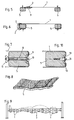
- FIG. 1 and 2 show a side view of a band 1 or a belt.
- This tape is designed similar to a seat belt for motor vehicles. It consists of a dense fabric and has no or only a small, negligible Elongation.
- this band 1 or in its longitudinal course is an elastic Part 2 incorporated.
- This elastic part 2 can be made of a rubber elastic Band exist. But it is also possible to use mechanical tension springs here. It is essential that parallel to this elastic part 2 and this in the longitudinal direction of the band 1 bridging a band part 3 is fixed, the with regard to its structure and its stretching properties the volume 1 corresponds.
- This band part 3 is longer than the unloaded part 2, so that this band part 3 is drawn sagging in Fig. 1, because in this illustration the elastic part 2 is not under tension.
- the length l of the unloaded, elastic part 2 is considerably smaller than the length L of the band 1.
- the tape 1 is subjected to a force P on tension, only the can to stretch and stretch elastic part 2 and to increase its length l, however, this only to an extent A, which is the length of the bridging band part 3 allows.
- Belts or straps 1 of the type explained with reference to FIGS. 1 and 2 are now part a lying element 4 shown in oblique view in FIG. 3, which is shown in FIG Embodiment has a support frame, not shown, with longitudinal support parts 5. These bands 1 extend transversely to these longitudinal support parts 5.
- the not Support frame shown in detail with the longitudinal support parts 5 is here from a frame 6 added.
- Fig. 4 shows schematically a cross section through a first embodiment of such a bed element.
- the band 1 is designed as an endless band with an upper and a lower strand, with the elastic one in the lower strand Part 2 and the band part 3 bridging this elastic part 2 are arranged are.
- This circulating belt can be attached to one of the two longitudinal support parts 5 be fixed.
- the band 1 two ends. These ends are in a suitable manner on the longitudinal support parts 5 fixed.
- the elastic part 2 and the band part 3 bridging this part are arranged here in the actual support part of the bed element.
- FIG. 6 illustrates an exemplary embodiment.
- band 1 has two Ends that are partly wrapped around the longitudinal support parts 5.
- the elastic Part 2 and the band part 3 bridging it are arranged laterally here.
- a large number of such bands 1 is now along the length of the lying element used parts 2 and 3 provided.
- the length of the elastic parts 2 is at all tapes 1 of a bed element dimensioned essentially the same size. If here and elsewhere the length of the elastic part 2 is mentioned is, the length of the unloaded elastic part 2 is always meant.
- the lengths of the band parts 3 bridging them are of different sizes dimensioned, in such a way that this length depends on the location of the band 1 within the bed element. This length of bridging Band part 3 is chosen so that the bands 1 lie under the load of a Extend person (see Fig.
- the longitudinal support parts 5 will be formed by straight bars. It is but also possible, these longitudinal support parts of the back ideal body contour to adapt to a person. This is shown schematically in FIG. 8 on a bed element shown. Such curved spars can be easily produced are glued together by individual relatively thin longitudinal slats and introduced into a correspondingly pre-designed form.
- Fig. 7 now shows in detail how this bias can be regulated and is adjustable.
- Push-through holes 8 are provided, the outer opening 9 of which is located is expanded compared to the diameter of the bore.
- the number of these through holes corresponds to the number of bands 1, the pretension adjustable should be.
- the adjustable bands 1 are widened via this bore 8 or its bore Mouth opening 9 out.
- a head screw 10 is inserted, the inside of which protrudes End carries a wing nut 11.
- the wing nut 11 By tightening or loosening the wing nut 11 can regulate the above-mentioned bias within certain limits be to the couch element to a predetermined, specific body shape as possible adapt exactly and thereby the expected healing success, which results from the Use of such a bed element results in favorable influence. It is also possible, for the same purpose over the length of at least one Longitudinal support part 5, namely on the outside of a longitudinal groove 12 to provide, over which the individual strips 1 run. Congruent with the groove 12 then a tab 13 is placed on each band 1, the outside is clamped by means of a screw 14. By the extent to which this Screw 14 is screwed into the longitudinal support part 5, the bias of a each volume 1 can be set.
Landscapes
- Invalid Beds And Related Equipment (AREA)
- Orthopedics, Nursing, And Contraception (AREA)
Abstract
Description
Die Erfindung bezieht sich auf ein Liege- oder Sitzelement mit den Merkmalen
des Oberbegriffes des Patentanspruches 1.The invention relates to a lying or sitting element with the features
the preamble of
Ein solches Liege- oder Sitzelement ist aus der EP 270 582 A1 bekannt. Das Charakteristische dieses Liege- oder Sitzelementes liegt darin, daß die Bänder oder Gurte zur Anpassung an die ideale Körperkontur des das Liege- oder Sitzelement Benutrenden verschieden lang ausgeführt oder in verschiedenen Höhen an den Längstragteilen des Tragrahmens befestigt sind. Durch diese vorbekannte Maßnahme wird erreicht, daß längenmäßig abgestimmte Bänder oder Gurte vorhanden sind, die an die ideale Körperkontur anpaßbar sind. Eine Einrichtung dieser Art dient vor allem zur Entlastung der Bandscheiben und der Wirbelsäule, und es wurden mit solchen Einrichtungen bereits beachtliche Heilerfolge erzielt.Such a lying or sitting element is known from EP 270 582 A1. The Characteristic of this lying or sitting element is that the bands or straps to adapt to the ideal body contour of the lying or sitting element Use of different lengths or at different heights are attached to the longitudinal support parts of the support frame. Through this previously known Measure is achieved that belts or belts coordinated in length are present are that are adaptable to the ideal body contour. An establishment of this Art mainly serves to relieve the intervertebral discs and spine, and remarkable healing successes have already been achieved with such facilities.
In diesem Zusammenhang ist auch das Liegeelement nach der US-A-2 788 531 zu erwähnen, die eine vergleichbare Konstruktion zeigt und beschreibt. An den Längstragteilen des Tragrahmens sind die einzelnen Bänder mit diese Längstragteile umfassenden Schlaufen befestigt. Diese Schlaufen sind aus gummielastischem Material gefertigt. Die Schlaufen der auf die Länge des Tragrahmens aufeinanderfolgenden Bänder sind unterschiedlich lang, so daß die einzelnen Bänder, in Abhängigkeit der Länge der elastischen Schlaufen, unterschiedlich weit bei der vorgesehenen Belastung durchhängen. Diese elastischen Schlaufen der einzelnen Bänder werden bei der bestimmungsgemäßen Verwendung des Liegeelementes jeweils bis zu ihrer Streckgrenze belastet. Diese Belastung beeinträchtigt die Lebensdauer der Bänder nicht unerheblich, aus welchem Grund Liegeelemente dieser Art sich auf dem Markt nicht haben durchsetzen können.In this connection is also the couch element according to US-A-2 788 531 to mention, which shows and describes a comparable construction. To the The longitudinal members of the support frame are the individual bands with these longitudinal members attached loops. These loops are made of elastic rubber Made of material. The loops of the successive to the length of the support frame Bands are of different lengths, so that the individual bands, depending on the length of the elastic loops, at different levels sag the intended load. These elastic loops of the individual Bands are used when the bed element is used as intended each loaded up to its yield point. This burden affects the lifespan of the tapes is not irrelevant, for which reason lying elements of this kind could not have prevailed on the market.
Ausgehend von diesem Stand der Technik zielt die Erfindung auf eine Verbesserung
ab und dies wird durch jene Maßnahmen erreicht, die Inhalt und Gegenstand
des kennzeichnenden Teiles des Patentanspruches 1 sind. Zweckmäßige
Ausgestaltungen der Erfindung sind dabei in den Unteransprüchen festgelegt. Die
angestrebte Verbesserung liegt vor allem darin, daß der Liege- oder Sitzkomfort
gegenüber der bekannten Konstruktion erhöht wird.Based on this prior art, the invention aims to improve
and this is achieved through those measures, the content and subject
of the characterizing part of
Um die Erfindung zu veranschaulichen, wird sie anhand mehrerer Ausführungsbeispiele
näher beschrieben. Es zeigen:
Die Fig. 1 und 2 zeigen in Seitensicht ein Band 1 oder einen Gurt. Dieses Band
ist ähnlich ausgebildet wie ein Sicherheitsgurt für Kraftfahrzeuge. Es besteht aus
einem dichten Gewebe und besitzt keine bzw. nur eine geringe, vernachlässigbare
Längsdehnung. In dieses Band 1 bzw. in dessen Längsverlauf ist ein elastischer
Teil 2 eingearbeitet. Dieser elastische Teil 2 kann aus einem gummielastischen
Band bestehen. Es aber auch möglich, hier mechanische Zugfedern einzusetzen.
Wesentlich ist nun, daß parallel zu diesem elastischen Teil 2 und diesen
in Längsrichtung des Bandes 1 überbrückend ein Bandteil 3 festgelegt ist, der
hinsichtlich seines Aufbaues und seiner Dehnungseigenschaften dem Band 1
entspricht. Dieser Bandteil 3 ist aber länger als der unbelastete Teil 2, so daß
dieser Bandteil 3 in Fig. 1 durchhängend gezeichnet ist, da in dieser Darstellung
der elastische Teil 2 nicht auf Zug beansprucht ist. Die Länge l des unbelasteten,
elastischen Teiles 2 ist dabei erheblich kleiner als die Länge L des Bandes 1.1 and 2 show a side view of a
Wird das Band 1 durch eine Kraft P auf Zug beansprucht, so vermag sich nur der
elastische Teil 2 zu strecken und zu dehnen und seine Länge l zu vergrößern,
dies jedoch nur in einem Ausmaß A, das die Länge des überbrückenden Bandteiles
3 zuläßt.If the
Werden Bänder 1 vorgegebener gleicher Länge L vorausgesetzt und in diese
Bänder 1 gleiche elastische Teile 2 der gleichen Länge l eingefügt, so können
diese Bänder 1 um unterschiedliche Maße A gedehnt werden, wenn die überbrückenden
Bandteile 3 unterschiedlich lang sind. Die Länge der elastischen
Teile 2 und die Länge der sie überbrückenden Bandteile 3 sind aufeinander abzustimmen,
und zwar in der Weise, daß die Länge des überbrückenden Sandtees
3 stets kürzer ist als die maximale Dehnbarkeit des elastischen Teiles 2, mit
anderen Worten, die Länge des überbrückenden Bandteiles 3 ist stets kürzer als
die Länge des maximal gestreckten oder maximal gedehnten elastischen Bandes
2. um eine Überbeanspruchung des elastischen Teiles zu vermeiden und damit
seine Lebensdauer zu erhöhen.Are
Bänder oder Gurte 1 der anhand der Fig. 1 und 2 erläuterten Art sind nun Teil
eines in Fig. 3 in Schrägsicht gezeigten Liegeelementes 4, das in der gezeigten
Ausführungsform einen nicht dargestellten Tragrahmen mit Längstragteilen 5 besitzt.
Diese Bänder 1 erstrecken sich quer zu diesen Längstragteilen 5. Der nicht
näher dargestellte Tragrahmen mit den Längstragteilen 5 ist hier von einem Gestell
6 aufgenommen.Belts or
Fig. 4 zeigt schematisch einen Querschnitt durch eine erste Ausführungsform
eines solchen Liegeelementes. Hier ist das Band 1 als endloses Band ausgebildet
mit einem oberen und einem unteren Trum, wobei im unteren Trum der elastische
Teil 2 und der diesen elastischen Teil 2 überbrückende Bandteil 3 angeordnet
sind. Dieses umlaufende Band kann an einem der beiden Längstragteile 5
fixiert sein.Fig. 4 shows schematically a cross section through a first embodiment
of such a bed element. Here the
Bei einem anderen Ausführungsbeispiel, wie in Fig. 5 gezeigt, besitzt das Band 1
zwei Enden. Diese Enden sind in geeigneter Weise an den Längstragteilen 5
festgelegt. Der elastische Teil 2 und der diesen Teil überbrückende Bandteil 3
sind hier im eigentlichen Auflageteil des Liegeelementes angeordnet. Ein weiteres
Ausführungsbeispiel veranschaulicht die Fig. 6. Auch hier besitzt das Band 1 zwei
Enden, die zum Teil um die Längstragteile 5 geschlungen sind. Der elastische
Teil 2 und der ihn überbrückende Bandteil 3 sind hier seitlich angeordnet.In another embodiment, as shown in FIG. 5, the
Über die Länge des Liegeelementes ist nun eine Vielzahl solcher Bänder 1 mit
eingesetzten Teilen 2 und 3 vorgesehen. Die Länge der elastischen Teile 2 ist bei
allen Bändern 1 eines Liegeelementes im wesentlichen gleich groß bemessen.
Wenn hier und an anderer Stelle von der Länge des elastischen Teiles 2 die Rede
ist, so ist stets die Länge des unbelasteten elastischen Teiles 2 gemeint. Hingegen
sind die Längen der sie überbrückenden Bandteile 3 unterschiedlich groß
bemessen, und zwar in der Weise, daß diese Länge abhängig ist von der Lage
des Bandes 1 innerhalb des Liegeelementes. Diese Länge des überbrückenden
Bandteiles 3 ist so gewählt, daß sich die Bänder 1 unter der Last einer liegenden
Person (vgl. Fig. 9) unterschiedlich stark verlängern, so daß sich die untere Kontur
des bestimmungsgemäß belasteten Liegeelementes einer idealen Rückenkontur
anpaßt, wie dies beim vorbekannten Liegeelement nach EP 270 582 der
Fall ist. Die lastabhängig beanspruchten Bänder 1 - siehe Fig. 9 - sind dann jeweils
gestreckt, wie in Fig. 2 gezeigt, diese Bänder sind von der auf ihnen ruhenden
Last vollständig gestreckt, so daß jeweils der überbrückende Bandteil 3 einen
erheblichen Anteil der im Band aufgrund der Belastung herrschenden Zugbeanspruchung
übernommen hat.A large number of
In der Regel werden die Längstragteile 5 durch gerade Holme gebildet sein. Es ist
aber auch möglich, diese Längstragteile der rückseitigen idealen Körperkontur
eines Menschen anzupassen. Das ist in Fig. 8 schematisch an einem Liegeelement
dargestellt. Solche gebogen verlaufende Holme können ohne weiteres hergestellt
werden, indem einzelne relativ dünne Längslamellen miteinander verleimt
und in eine entsprechend vorgestaltete Form eingebracht werden.As a rule, the
Wird das Band 1 oder werden die Bänder 1 am Tragrahmen festgelegt, so geschieht
dies in der Weise, daß der elastische Teil eines jeden Bandes 1 etwas
vorgespannt wird. Fig. 7 zeigt nun im Detail, wie diese Vorspannung regelbar und
einstellbar ist. In wenigstens einem der beiden Längstragteile 5 sind horizontale
Durchsteckbohrungen 8 vorgesehen, deren außen liegende Mündungsöffnung 9
gegenüber dem Durchmesser der Bohrung erweitert ist. Die Anzahl dieser Durchsteckbohrungen
entspricht der Anzahl der Bänder 1, deren Vorspannung regelbar
sein soll. Die regelbaren Bänder 1 werden über diese Bohrung 8 bzw. deren verbreiterte
Mündungsöffnung 9 geführt. Durch das Band 1 und durch die Durchsteckbohrung
8 wird eine Kopfschraube 10 gesteckt, deren nach innen vorstehendes
Ende eine Flügelmutter 11 trägt. Durch Anziehen oder Lösen der Flügelmutter
11 kann die oben erwähnte Vorspannung in gewissen Grenzen geregelt
werden, um das Liegeelement an eine vorgegebene, bestimmte Körperform möglichst
exakt anzupassen und dadurch den zu erwartenden Heilerfolg, der aus der
Benutzung eines solchen Liegeelementes resultiert, günstig zu beeinflussen. Es
ist auch möglich, und zwar für den selben Zweck über die Länge mindestens eines
Längstragteiles 5, und zwar an dessen Außenseite eine längsverlaufende Nut
12 vorzusehen, über welche die einzelnen Bänder 1 verlaufen. Deckungsgleich
mit der Nut 12 wird dann an jedes Band 1 eine Lasche 13 gelegt, die von außen
mittels einer Schraube 14 festgespannt wird. Durch das Ausmaß in dem diese
Schraube 14 in den Längstragteil 5 eingedreht wird, kann die Vorspannung eines
jeden Bandes 1 eingestellt werden. If the
- 11
- Band oder GurtTape or strap
- 22nd
- elastischer Teilelastic part
- 33rd
- überbrückender Bandteilbridging band part
- 44th
- LiegeelementCouch element
- 55
- LängstragteilLongitudinal section
- 66
- Gestellframe
- 77
- Konturcontour
- 88th
- DurchsteckbohrungThrough hole
- 99
- MündungsöffnungMouth opening
- 1010th
- KopfschraubeCap screw
- 1111
- FlügelmutterWing nut
- 1212th
- NutGroove
- 1313
- LascheTab
- 1414
- Schraubescrew
Claims (12)
Applications Claiming Priority (3)
| Application Number | Priority Date | Filing Date | Title |
|---|---|---|---|
| AT152097 | 1997-09-10 | ||
| AT152097A AT405013B (en) | 1997-09-10 | 1997-09-10 | Lying or seating element |
| AT1520/97 | 1997-09-10 |
Publications (2)
| Publication Number | Publication Date |
|---|---|
| EP0903093A2 true EP0903093A2 (en) | 1999-03-24 |
| EP0903093A3 EP0903093A3 (en) | 2000-04-19 |
Family
ID=3515410
Family Applications (1)
| Application Number | Title | Priority Date | Filing Date |
|---|---|---|---|
| EP98115493A Withdrawn EP0903093A3 (en) | 1997-09-10 | 1998-08-18 | An element for seating or lying |
Country Status (2)
| Country | Link |
|---|---|
| EP (1) | EP0903093A3 (en) |
| AT (1) | AT405013B (en) |
Citations (2)
| Publication number | Priority date | Publication date | Assignee | Title |
|---|---|---|---|---|
| US2788531A (en) | 1953-12-30 | 1957-04-16 | Cornell Aeronautical Labor Inc | Self-equalizing, self-aligning body support |
| EP0270582A1 (en) | 1986-05-22 | 1988-06-15 | Hermann Huemer | Element for reclining or sitting. |
Family Cites Families (3)
| Publication number | Priority date | Publication date | Assignee | Title |
|---|---|---|---|---|
| GB162031A (en) * | 1920-05-06 | 1921-04-28 | Albert Edward Starling | Improvements in the manufacture of chairs, couches, mattresses, and the like |
| US1426972A (en) * | 1922-06-14 | 1922-08-22 | Orma N Farnham | Spring bed |
| CH205121A (en) * | 1938-03-25 | 1939-06-15 | Jules Westheimer A G | Elastic element intended for attachment to a frame, especially for supporting cushions, mattresses, etc. for armchairs, couches, etc. |
-
1997
- 1997-09-10 AT AT152097A patent/AT405013B/en not_active IP Right Cessation
-
1998
- 1998-08-18 EP EP98115493A patent/EP0903093A3/en not_active Withdrawn
Patent Citations (2)
| Publication number | Priority date | Publication date | Assignee | Title |
|---|---|---|---|---|
| US2788531A (en) | 1953-12-30 | 1957-04-16 | Cornell Aeronautical Labor Inc | Self-equalizing, self-aligning body support |
| EP0270582A1 (en) | 1986-05-22 | 1988-06-15 | Hermann Huemer | Element for reclining or sitting. |
Also Published As
| Publication number | Publication date |
|---|---|
| AT405013B (en) | 1999-04-26 |
| EP0903093A3 (en) | 2000-04-19 |
| ATA152097A (en) | 1998-09-15 |
Similar Documents
| Publication | Publication Date | Title |
|---|---|---|
| DE60310608T2 (en) | DIFFERENTLY HIGH POCKET MATRAT | |
| EP1056371B1 (en) | Bedstead | |
| DE10057208A1 (en) | Sitting and / or lying device, in particular passenger seat with adjustable backrest | |
| DE60210992T2 (en) | Device for fastening a spring strip to the frame of a slatted frame | |
| DE2707046C2 (en) | ||
| EP0050293A2 (en) | Device for the elastic reinforcement of selectable subareas of slatted frames for lounging furniture | |
| CH386619A (en) | Support device for the human body | |
| EP0236292A2 (en) | Slatted bed base | |
| DE2756477C2 (en) | Slatted frame with support slats connected by a belt | |
| EP0903093A2 (en) | An element for seating or lying | |
| EP0116106B1 (en) | Slat-type mattress with webbing | |
| DE8424784U1 (en) | WOODEN LATTENING | |
| WO1996028072A1 (en) | Wooden slatwork for beds and chairs | |
| DE2330463A1 (en) | Head support for vehicle seats - has tensioning device for net type headrest cushion stretched round inverted U framework | |
| DE29617272U1 (en) | Bed system for a bed | |
| AT404091B (en) | MAT FOR LYING AREAS, IN PARTICULAR FOR MATTRESSES | |
| DE3429004A1 (en) | Endless connection for screen-bar bands | |
| DE20207959U1 (en) | slatted | |
| DE10322189B4 (en) | lumbar support | |
| DE3237132C2 (en) | ||
| AT210351B (en) | Transport unit | |
| DE3612603A1 (en) | Lath grid for beds or the like | |
| DE2951691C2 (en) | Zipper | |
| EP3047759A1 (en) | Spring body for sitting or lying furniture | |
| DE1939582C (en) | Mattress frame |
Legal Events
| Date | Code | Title | Description |
|---|---|---|---|
| PUAI | Public reference made under article 153(3) epc to a published international application that has entered the european phase |
Free format text: ORIGINAL CODE: 0009012 |
|
| AK | Designated contracting states |
Kind code of ref document: A2 Designated state(s): AT BE CH CY DE DK ES FI FR GB GR IE IT LI LU MC NL PT SE |
|
| AX | Request for extension of the european patent |
Free format text: AL;LT;LV;MK;RO;SI |
|
| PUAL | Search report despatched |
Free format text: ORIGINAL CODE: 0009013 |
|
| AK | Designated contracting states |
Kind code of ref document: A3 Designated state(s): AT BE CH CY DE DK ES FI FR GB GR IE IT LI LU MC NL PT SE |
|
| AX | Request for extension of the european patent |
Free format text: AL;LT;LV;MK;RO;SI |
|
| AKX | Designation fees paid | ||
| STAA | Information on the status of an ep patent application or granted ep patent |
Free format text: STATUS: THE APPLICATION IS DEEMED TO BE WITHDRAWN |
|
| 18D | Application deemed to be withdrawn |
Effective date: 20001020 |
|
| REG | Reference to a national code |
Ref country code: DE Ref legal event code: 8566 |