EP0903130A2 - Dispositif d'ostomie - Google Patents
Dispositif d'ostomie Download PDFInfo
- Publication number
- EP0903130A2 EP0903130A2 EP98307131A EP98307131A EP0903130A2 EP 0903130 A2 EP0903130 A2 EP 0903130A2 EP 98307131 A EP98307131 A EP 98307131A EP 98307131 A EP98307131 A EP 98307131A EP 0903130 A2 EP0903130 A2 EP 0903130A2
- Authority
- EP
- European Patent Office
- Prior art keywords
- pouch
- filter
- filter element
- bore
- deodorising
- Prior art date
- Legal status (The legal status is an assumption and is not a legal conclusion. Google has not performed a legal analysis and makes no representation as to the accuracy of the status listed.)
- Granted
Links
- 239000000463 material Substances 0.000 claims abstract description 45
- 230000008878 coupling Effects 0.000 claims abstract description 29
- 238000010168 coupling process Methods 0.000 claims abstract description 29
- 238000005859 coupling reaction Methods 0.000 claims abstract description 29
- 239000007788 liquid Substances 0.000 claims abstract description 26
- 235000019504 cigarettes Nutrition 0.000 claims abstract description 13
- 230000004323 axial length Effects 0.000 claims abstract description 5
- 238000000034 method Methods 0.000 claims description 18
- 239000007789 gas Substances 0.000 claims description 15
- 238000007455 ileostomy Methods 0.000 claims description 13
- XLYOFNOQVPJJNP-UHFFFAOYSA-N water Substances O XLYOFNOQVPJJNP-UHFFFAOYSA-N 0.000 claims description 11
- 206010016766 flatulence Diseases 0.000 claims description 10
- OKTJSMMVPCPJKN-UHFFFAOYSA-N Carbon Chemical compound [C] OKTJSMMVPCPJKN-UHFFFAOYSA-N 0.000 claims description 8
- 238000003780 insertion Methods 0.000 claims description 7
- 230000037431 insertion Effects 0.000 claims description 7
- 239000002195 soluble material Substances 0.000 claims description 7
- 230000005484 gravity Effects 0.000 claims description 3
- 229920001495 poly(sodium acrylate) polymer Polymers 0.000 claims description 2
- 230000000717 retained effect Effects 0.000 claims description 2
- NNMHYFLPFNGQFZ-UHFFFAOYSA-M sodium polyacrylate Chemical compound [Na+].[O-]C(=O)C=C NNMHYFLPFNGQFZ-UHFFFAOYSA-M 0.000 claims description 2
- 230000000873 masking effect Effects 0.000 claims 4
- 230000000295 complement effect Effects 0.000 claims 1
- 230000001419 dependent effect Effects 0.000 claims 1
- 238000004519 manufacturing process Methods 0.000 abstract description 12
- 210000002700 urine Anatomy 0.000 description 11
- 239000004372 Polyvinyl alcohol Substances 0.000 description 8
- 229920002451 polyvinyl alcohol Polymers 0.000 description 8
- 235000019422 polyvinyl alcohol Nutrition 0.000 description 8
- 229920003023 plastic Polymers 0.000 description 7
- 239000004033 plastic Substances 0.000 description 7
- 239000007787 solid Substances 0.000 description 7
- 238000013461 design Methods 0.000 description 6
- -1 for example Substances 0.000 description 5
- 239000008187 granular material Substances 0.000 description 3
- 230000014759 maintenance of location Effects 0.000 description 3
- 239000002002 slurry Substances 0.000 description 3
- RAHZWNYVWXNFOC-UHFFFAOYSA-N Sulphur dioxide Chemical compound O=S=O RAHZWNYVWXNFOC-UHFFFAOYSA-N 0.000 description 2
- 238000010521 absorption reaction Methods 0.000 description 2
- 239000000853 adhesive Substances 0.000 description 2
- 230000001070 adhesive effect Effects 0.000 description 2
- 230000004888 barrier function Effects 0.000 description 2
- 238000011161 development Methods 0.000 description 2
- 230000018109 developmental process Effects 0.000 description 2
- 230000000694 effects Effects 0.000 description 2
- 229940127554 medical product Drugs 0.000 description 2
- 238000012986 modification Methods 0.000 description 2
- 230000004048 modification Effects 0.000 description 2
- 238000012545 processing Methods 0.000 description 2
- 101710083129 50S ribosomal protein L10, chloroplastic Proteins 0.000 description 1
- 230000000903 blocking effect Effects 0.000 description 1
- 239000000084 colloidal system Substances 0.000 description 1
- 238000010276 construction Methods 0.000 description 1
- 239000000645 desinfectant Substances 0.000 description 1
- 239000000835 fiber Substances 0.000 description 1
- 229920001477 hydrophilic polymer Polymers 0.000 description 1
- 238000002955 isolation Methods 0.000 description 1
- 230000002093 peripheral effect Effects 0.000 description 1
- 239000011148 porous material Substances 0.000 description 1
- 239000003755 preservative agent Substances 0.000 description 1
- 230000001681 protective effect Effects 0.000 description 1
- 238000000926 separation method Methods 0.000 description 1
- 238000002791 soaking Methods 0.000 description 1
- 235000010269 sulphur dioxide Nutrition 0.000 description 1
- 239000004291 sulphur dioxide Substances 0.000 description 1
- 230000008961 swelling Effects 0.000 description 1
Images

Classifications
-
- A—HUMAN NECESSITIES
- A61—MEDICAL OR VETERINARY SCIENCE; HYGIENE
- A61F—FILTERS IMPLANTABLE INTO BLOOD VESSELS; PROSTHESES; DEVICES PROVIDING PATENCY TO, OR PREVENTING COLLAPSING OF, TUBULAR STRUCTURES OF THE BODY, e.g. STENTS; ORTHOPAEDIC, NURSING OR CONTRACEPTIVE DEVICES; FOMENTATION; TREATMENT OR PROTECTION OF EYES OR EARS; BANDAGES, DRESSINGS OR ABSORBENT PADS; FIRST-AID KITS
- A61F5/00—Orthopaedic methods or devices for non-surgical treatment of bones or joints; Nursing devices ; Anti-rape devices
- A61F5/44—Devices worn by the patient for reception of urine, faeces, catamenial or other discharge; Colostomy devices
- A61F5/441—Devices worn by the patient for reception of urine, faeces, catamenial or other discharge; Colostomy devices having venting or deodorant means, e.g. filters ; having antiseptic means, e.g. bacterial barriers
Definitions
- This invention relates generally to ostomy appliances.
- the invention relates to a deodorising filter arrangement for an ostomy pouch.
- the invention relates to a superabsorbent member suitable for use in an ostomy pouch, and also to a method of introducing the superabsorbent member into a pouch.
- This aspect of the invention is particularly suitable for use with ileostomy pouches or urostomy pouches, but it is not limited only to such applications
- one aspect of the present invention is to employ a filter housing having a bore therein, and an elongate deodorising filter element received or receivable longitudinally within the bore.
- the bore preferably has a longitudinal dimension greater than its, or a, lateral dimension.
- the gas flow through the deodorising filter element is generally in an axial direction.
- elongate is used herein broadly to mean that the length is greater than the, or a, lateral dimension.
- the bore and the filter element are generally cylindrical, although this is not essential in all embodiments.
- the bore is generally straight.
- the ends of the bore may be generally transverse to the axis of the bore, or one or both ends may be inclined relative to the axis.
- the bore is preferably of about the same length as the filter element, whereas in the latter case, the bore is preferably longer than the filter element (to ensure that the filter element is contained within the bore along its entire length.
- the filter element is a snug fit within the bore, and is retained in position by frictional engagement between the filter and the inner surface of the bore.
- One or more projections may be provided on the inner surface of the bore to grip the filter element.
- one or more end members for example, end covers, may be employed to contain the filter within the bore.
- the filter element can be positioned within the bore manually by being slid into the bore through one end. Preferably, this can be performed by the ostomate while wearing the pouch, or prior to wearing the pouch.
- an existing filter element positioned within the bore is displaceable, or ejectable, through one end of the bore by insertion of a new filter element through the opposite end.
- This can allow simple filter replacement without a person having to open, and then re-secure, the filter housing to access the filter element as in many prior art designs (which in some cases may require considerable dexterity).
- the bore is arranged with one end opening into the pouch, so that the ejected filter element can drop into the pouch.
- a filter may normally accumulate faecal matter, or slurry, on its surface, particularly if the pouch is almost full, or if the faecal matter has leaked into the filter compartment for other reasons. Handling such contaminated filters presents a hygiene risk. Moreover, it may not always be convenient to dispose of the old filter.
- a range of different filter elements be provided to enable an ostomate to select a filter with an optimum flow rate characteristic.
- the flow rate characteristic may be controlled by varying, for example, the filter density, pore density, or the tortuosity through the filter.
- the pouch may be supplied with a packet of such different filter elements, or the ostomate may be able to purchase a packet of different, or the same, filter elements separately. The ostomate can then insert the desired filter element into the housing prior to wearing the pouch.
- the filter elements may, for example, be coloured differently to indicate different flow rates.
- the filter housing is incorporated within a coupling member of an ostomy coupling.
- the filter is preferably incorporated in the bag-side coupling member, but could also be incorporated within the bodyside coupling member if desired.
- the invention provides a deodorising ostomy filter, comprising:
- the gas flow path within the bore is in one or more generally axial directions.
- the bore and the filter element are generally cylindrical.
- the filter element is insertable into one end of the bore. More preferably, the filter element is ejectable through one end of the bore by insertion of a replacement filter element through the opposite end.
- the invention provides an ostomy pouch including a deodorising filter, the deodorising filter comprising:
- the object is a replacement filter element.
- the invention provides an ostomy deodorising filter element, the element being generally cylindrical and having an axial length greater than its radial dimension, and preferably greater than is diameter.
- the filter element is relatively rigid.
- the filter element may be encased in a sleeve to assist retention of the element's shape.
- the sleeve may be rigid or semi-rigid.
- the sleeve may be of a water-soluble material, for example, polyvinyl alcohol.
- the filter element contains superabsorbent material for absorbing any liquid which leaks or soaks into the filter element. This is particularly advantageous for filter or pouch configurations in which no protective barrier is provided to obstruct the passage of liquid into the filter.
- the invention provides a method of replacing a filter element in a pouch having a filter housing in a bore of which is received an elongate filter element, the method comprising:
- the above method steps may be performed separately, but preferably are carried out simultaneously as a single method step of inserting a new filter element into the bore, which acts as an object to push the existing filter from the bore and into the pouch.
- the invention provides a method of replacing a filter element in a pouch having a filter housing in a bore of which is received an elongate filter element, the method comprising:
- the invention provides a method of forming deodorising filter elements for ostomy pouches, the method comprising forming an elongate rod of filter material, and cutting or slicing the rod into discrete elements.
- the elements may have a transverse dimension which is less than the, or a longitudinal dimension, as described above.
- the elements may be in the form of slices having a transverse dimension greater than their axial thickness. Such elements could then be used a filter "discs" or layers in a conventional filter envelope of an ostomy pouch.
- the filter elements are generally cylindrical.
- the invention provides an ostomy pouch comprising a filter as aforesaid in any preceding aspect.
- the filter may either be received within a plastics housing, or it may received within an envelope or compartment formed by one or more sheets of plastics film, or it may be attached directly to a wall of the pouch.
- urostomy pouches normally employ a non-return valve in their uppermost region, through which the superabsorbent material has to be inserted.
- the valve is commonly formed by welds which hold the pouch walls together. The effect is to allow liquid entering the pouch to dribble through the valve under gravity, but substantially avoid any liquid in the pouch from splashing back through the valve as the wearer moves about.
- GB-A-2 268 882 describes a tubular applicator with which the superabsorbent sheet can be inserted through the non-return valve in rolled-up form.
- ileostomy pouches do not employ a non-return valve, but it can nevertheless be quite difficult for a user to insert a superabsorbent sheet into the pouch, particularly for small diameter aperture pouches.
- pouches are often emptyable, and will require a new superabsorbent sheet to be inserted for each new use. It can be difficult for a user to insert the sheet without his or her hands contacting the inner surface of the pouch which may be fouled with ileostomy slurry. Such contact is unhygenic, unpleasant and embarrassing for the wearer.
- the present invention has been devised bearing the above problems in mind.
- one aspect of the invention is to provide a superabsorbent member (i.e. a member comprising or containing superabsorbent material) in a rigid or semi-rigid, elongate, stick or rod form.
- a superabsorbent member i.e. a member comprising or containing superabsorbent material
- Such a stick or rod can simply be inserted by hand endwise through the aperture and non-return valve of a urostomy pouch, without becoming fouled by the valve, and without the need for an applicator.
- the member is preferably at least sufficiently rigid that it can be forced through the non-return valve.
- the stick or rod can also be inserted easily into an ileostomy pouch, and manoeuvred and manipulated more easily into position, without the user having to touch the inner surface of the pouch.
- the superabsorbent member is made substantially entirely of one or more water gellable materials and/or of one or more water soluble materials.
- liquid e.g. urine in the pouch
- the member can disintegrate without leaving any solid parts behind. This can avoid any solid parts in the pouch contents when the pouch is, for example, emptied into a toilet in a conventional manner.
- the superabsorbent member is formed in a similar manner to a conventional cigarette filter.
- Granules, or powder-like micro-granules, of superabsorbent matcrial can be packed into, or distributed in or on a wad of material to form, an elongate stick or rod using processing similar to that used conventionally in the cigarette filter production industry.
- a particular advantage is that such members may be produced using the existing, proven production facilities already used in the cigarette filter industry, with little, if any, modifications being required to produce a batch of superabsorbent containing members.
- the superabsorbent may be carried on material which is itself water soluble.
- a suitable material may be polyvinyl alcohol PVOH (either in film, fibre or filament form).
- the member may comprise an outer sleeve or case to protect and maintain the shape of the stick or rod member.
- the sleeve or case is of water soluble material, for example, polyvinyl alcohol.
- the member may alternatively comprise a sleeve or case containing superabsorbent granules.
- the sleeve or case may be of a water soluble material, for example, polyvinyl alcohol.
- Superabsorbent materials are known per se, and are available from a number of different manufacturers.
- An example is the material Salsorb CL10 produced by Allied Colloids.
- the invention provides a member as aforesaid, and an ostomy pouch having an opening (either a permanent opening, or a closable opening) through which the member can be introduced into the pouch.
- the opening may, for example, be the stoma aperture, or it may, for example, be a closable drain.
- the invention provides a pouch (for example, a urostomy pouch) and a superabsorbent or superabsorbent-containing member, the urostomy pouch comprising an inlet aperture and a non-return (or anti-splash) valve adjacent to the aperture, and the member being provided in the form of a rigid or semi- rigid, elongate, stick or rod, the member being directly insertable through the aperture and the non-return valve into the liquid collecting chamber of the pouch.
- a pouch for example, a urostomy pouch
- a superabsorbent or superabsorbent-containing member comprising an inlet aperture and a non-return (or anti-splash) valve adjacent to the aperture
- the member being provided in the form of a rigid or semi- rigid, elongate, stick or rod, the member being directly insertable through the aperture and the non-return valve into the liquid collecting chamber of the pouch.
- the length of the member is greater than the minimum distance between the aperture and the non-return valve.
- the invention provides a method comprising:
- the invention provides a method comprising:
- an ostomy pouch 10 comprises a front wall 12 and a rear wall 14 of plastics film welded together around their periphery.
- a plastics bag-side coupling member 16 is welded to the rear wall 14 of the pouch as one half of a mechanical coupling for securing the pouch to a conventional body-side coupling member (not shown) attachable to the peristomal area of the ostomate by means of a conventional adhesive pad (not shown).
- the bag-side coupling member 16 consists of a generally flat flange 18 from which projects a generally cylindrical wall 20 surrounding the stomal aperture 22 of the pouch 10.
- the cylindrical wall 20 may be formed with, or support, a locking or latching element for engaging the body-side coupling member.
- Such elements are well known in the art, the reader being referred in particular to the snap-together coupling described in GB 1571657, and to the split-locking ring couplings described in EP 0737456 and EP 0737458.
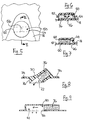
- a filter housing 24 is integrally moulded in an enlarged uppermost portion 26 of the flange 18 (i.e. uppermost when the pouch is viewed in its normal orientation).
- the filter housing 24 consists of a raised profile through which extends a generally cylindrical bore 28.
- the bore has an outer end, or mouth, 30 open to the external atmosphere, and an inner end 32 which is open to the interior of the pouch through a vent aperture 34 in the rear wall 14 of the pouch.
- the axial length of the bore is greater than the bore radius (and, in this embodiment, greater than the bore diameter).
- An elongate, generally cylindrical filter element 36 is received longitudinally within the bore 28.
- the filter element 36 is dimensioned to be a fairly snug fit within the bore 28 and, in use, is held in position by friction.
- one or more projecting ribs may be provided on the inside face of the bore 28 to increase the grip on the filter element 36.
- the filter element 36 consists of a cylindrical pack or wad 38 of suitable filter material such as activated carbon, or a material containing or carrying activated carbon.
- the wad may be at least slightly compressible to enable it to be received as a tight fit within the bore 28.
- the filter contains superabsorbent (liquid swellable) material to absorb any liquid which leaks into the filter element 36. This can substantially prevent, or at least delay, the passage of liquid soaking through the filter material, and thereby increase the effective life of the filter.
- a suitable superabsorbent material is a crosslinked hydrophilic polymer, for example. sodium polyacrylate.
- the superabsorbent may either be distributed throughout the filter material, or it may be a discrete mass (depicted in phantom by numeral 40) received, for example. within a recess or pocket of the wad 38.
- the wad 38 is surrounded by a cylindrical sleeve 42, for example, of paper or plastics film (for example, water soluble plastics (PVOH), to contain and protect the wad, and to provide the element with a degree of rigidity.
- the sleeve 42 is preferably of a flexible material, rather than a rigid shell.
- the swelling of the superabsorbent upon absorption of liquid could be used to block the filter once the superabsorbent has reached absorption saturation; the resulting ballooning of the pouch caused by trapped gas unable to vent through the filter, would then indicate to the ostomate that the filter needs replacing, as described further below.
- the filter element 36 is typically between about 1 cm and about 3cm in length, with a diameter of between about 0.5cm and about 1cm.
- the bore 28 has dimensions corresponding roughly to those of the filter, so that the raised portion of the housing does not need to project from the face of the pouch unnecessarily, and to provide the friction retention of the filter within the bore.
- the flange 16 may have a rear projection which projects into the interior of the pouch. This would enable the "height" of the exterior projection to be reduced, and could also provide a separation function to prevent the walls of the pouch from sticking together.
- the filter wad would then comprise a plurality of fibres or filaments packed together closely, and aligned generally in the longitudinal direction.
- the wad and/or the sleeve include or define one or more recesses or chambers for receiving the deodorising material.
- the filaments could comprise, or carry, the deodorising material.
- a fresh filter element 44 is simply inserted through the mouth 30 of the bore 28.
- the new filter element 44 contacts the existing filter element 26 and pushes it rearwards to be discharged or ejected through the inner end 32 of the bore.
- the discharged filter element 36 falls into the pouch, leaving the fresh filter element 44 in place in the bore 28. It will be appreciated that such filter replacement is extremely simple, and there is no need to dispose separately of the previous filter element 36, since this is automatically added to the pouch contents.
- the previous filter element 36 can be ejected before the new filter element 44 is inserted.
- the tip of a pencil can be inserted into the bore to force the existing filter element 36 into the pouch.
- the length of the filter element 36 has to be accommodated within the profile of the filter housing, the bore 28 being generally perpendicular to the plane of the flange 18.
- the projecting "height" on the exterior of the pouch can be reduced by employing a rear extension of the housing, and “sinking" the bore 28 relative to the flange.
- the bore 28 may be inclined diagonally relative to the flange, to accommodate the length of the bore 28 in a smaller "height" or housing thickness.
- the filter receiving bore does not extend through the flange and into the pouch. Instead, the bore 50 extends generally parallel to the plane of the flange, adjacent to its outer surface.
- the opposite ends 52 and 54 of the bore 50 are both open to the exterior atmosphere, and gas enters the filter from the pouch through a central aperture 56 in the wall of the bore 50 and the flange 18. The gas flow divides into two opposite axial paths to the opposite ends 52 and 54 of the bore.
- the filter element 36 is similar to that described above (but it is a requirement that gas can enter the filter midway along its length).
- the filter element 36 is replaceable by inserting a replacement filter element (not shown) into one end of the bore, to force the previous filter element to be ejected through the opposite end.
- the previous filter element 36 does not drop into the pouch, and will need to be disposed of separately. Nevertheless, such an arrangement does permit a gas-permeable, substantially liquid-impermeable barrier to be used (e.g. as illustrated in phantom by numeral 58) to prevent, or at least reduce, liquid contact with the filter.
- Fig. 7 illustrates a further embodiment which is similar to the second embodiment described above, but the bore 60 has only one end 62 open to the exterior atmosphere.
- the inner end 64 is closed, except for a passage 66 leading through the flange 18 and the pouch wall. In use, gas from the pouch vents through the passage 66, to the inner end 64 of the bore 60, and axially through the filter element 36 to the outer end 62 of the bore.
- Fig. 8 illustrates such a discrete filter embodiment.
- the filter housing 70 having a through bore 72 similar to the bore 28 to allow filter elements to be discharged into the pouch.
- the housing includes a peripheral flange 74 to allow the housing 70 to be welded or adhered to a pouch wall.
- the housing also includes a rear extension 76 of the type discussed previously to reduce the projecting profile of the housing.
- the bore 72 is inclined diagonally relative to the flange 74, to further reduce the projecting profile of the housing.
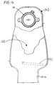
- Fig. 9 illustrates a fifth embodiment which is similar to the fourth embodiment described above.
- the bore 80 is generally parallel to the flange.
- a large open region 82 is provided at the inner end 84 of the bore 80 to allow a filter element discharged from the bore to fall sideways into the pouch.
- the length of the open region 82 is slightly greater than the length of the filter element, so that the filter element should be free to fall into the pouch.
- the open region 82 may be wider than the bore 80 so that there should be no tendency for the discharged filter element to stick to the wall of the housing.
- filter for a coupling member may also be used for a discrete filter, and the designs for a discrete filter may also be incorporated into a coupling member.
- a range of filter elements having different flow rate characteristics be provided, to enable the ostomate to choose the best filter to suit his or her personal needs. It will be appreciated that different people produce different amounts of flatus, and this also depends on the type of food eaten.
- the filter should be able to vent flatus at such a rate to avoid the pouch ballooning under normal circumstances, but should also provide sufficient resistance to prevent collapsing of the pouch (which might cause the front and rear walls to stick together).
- each pouch could be accompanied by a packet of different filter elements to enable the ostomate to select the most appropriate filter.
- the ostomate may be able to purchase packets of filters separately.
- the filters may initially be supplied with a "standard" filter element, the ostomate having the opportunity to customise the filter by inserting a different filter element to suit his or her needs.
- the filter could also be supplied initially with a solid plug element blocking the bore 28.
- the ostomate need then only fit a filter element if desired.
- first, second and fourth embodiments described above provide a very simple way of replacing the filter element.
- the disposal into the pouch of the used filter element, provided by the first and fourth embodiments, is very hygienic and avoids the need to handle and dispose separately of the old filter element.
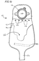
- a urostomy pouch 110 is formed by a front wall 112 and a rear wall 114 of plastics sheet, welded together around their periphery.
- a bagside connector 116 is secured to the rear wall 114 around a urine inlet aperture 118 in the rear wall 114.
- the connector 116 allows the pouch to be mechanically coupled to an adhesive bodyside component (not shown) worn by the ostomate.
- spot welds 120 securing the front and rear walls 112 and 114 together.
- the spot welds form a non-return, or anti-splash, valve for preventing urine in the main collection region 122 from splashing up to the aperture 118 a the wearer moves about.
- the front and rear walls are held in close contact with each other. Liquid entering the pouch through the aperture 118 is able to dribble through the gaps 124 between the spot welds, under gravity; however, liquid splashing inside the pouch is not able generally to pass back through the small gaps 124 (although the liquid might escape if the bag was inverted for any length of time).
- non-return valve may also be used, in particular other weld arrangements (for example as described in the above mentioned GB-A-2 268 882).
- the front and rear walls 112 and 114 define an integral outlet chute or tube 126 to facilitate emptying of the pouch.
- the outlet tube 126 is closed by means of a conventional clip (not shown), which squeezes the walls together to form a liquid tight seal.
- the tube 126 may be is relatively narrow, since the pouch will not be used to contain any solid matter.
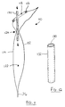
- a superabsorbent member 130 is provided for insertion into the pouch.
- the member 130 is generally rigid, or semi-rigid, and is in the form of an elongate rod or stick.
- the member 130 is generally cylindrical, having a diameter of between about 0.5 and about 2 cm, and a length of between about 2 and about 20 cm.
- the member 130 is sufficiently rigid to enable it to be introduced through the aperture, and forced through the non-return valve (i.e. through a gap 124 between two spot welds 120), into the liquid collection region 122 without the need for an applicator. This can be performed easily by hand, by inserting the member 130 endwise through the aperture, and advancing it downwardly. Once the member 130 has passed the non-return valve it sits in the liquid collection region 122 where it will gellify urine as the urine is collected in the pouch.
- the superabsorbent member is preferably produced by the conventional production facilities used in the cigarette filter industry.
- suitable elongate members can be formed by processing the material in the same way as in conventional cigarette filter production.
- the material is water soluble, for example, polyvinyl alcohol.
- the member also includes a generally cylindrical outer sleeve, also of water soluble material, for example, polyvinyl alcohol.
- the sleeve serves to protect and contain the superabsorbent-containing material, and can assist retention of the member's shape.
- the outer sleeve 132 dissolves, thereby allowing the superabsorbent material to contact, and gellify, the urine.
- the material on which the superabsorbent material is carried also dissolves, such that there are no solid parts remaining in the pouch contents, in this preferred embodiment.
- debris may remain in the pouch and require disposal with the pouch contents when the pouch is emptied.
- a new member 130 could be introduced through the drain tube 126, for example, after emptying, rather than through the inlet aperture.
- the use of a rigid (or semi-rigid) elongate member 130 can simplify introduction, being more easily controllable, and reduce the risk of the user's hand's touching the wet inner surfaces of the pouch and being fouled by urine on the pouch walls.
- Fig. 13 illustrates a second embodiment of urostomy pouch.
- This embodiment is very similar to the first embodiment described above, but the drain tube 126 is replaced by a tap positioned, for example on the front wall (shown schematically at 140).
- tap Many designs of tap are known in the art, varying from a narrow bore tube, which can be folded over to seal the tube (for example as illustrated in GB-A-2 058 011 - Kingsdown Medical Consultants), to a multi-piece tap (for example, a rotatable tap as illustrated in GB-A-2 101 274- Craig Medical Products).
- the superabsorbent member 130 can only be introduced through the inlet aperture, which emphasises the conventional problem of being able to manoeuvre the member through the non-return valve.
- the tap would be designed to enable the gelled contents of the bag to be forced through the tap upon squeezing the bag.
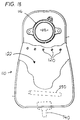
- Fig. 14 illustrates an ileostomy pouch 142.
- an ileostomy pouch is not normally provided with a non-return valve, and accordingly such a valve is omitted in this embodiment.
- the ileostomy pouch is similar to the first embodiment in that it has a drainage chute 144 at its lower ends, defined by the front and rear walls of the pouch. The drainage chute is closed in normal use by means of a clip (not shown). As can be seen in Fig. 14 the chute is generally wider than the chute 126 of the urostomy pouch, since the ileostomy pouch is required to be able to contain, at least some solid faecal matter, and to allow such solid matter to be emptied.
- the ability to be able to manoeuvre an elongate rigid, or semi-rigid, superabsorbent member into the pouch is especially advantageous for an ileostomy pouch, since after the initial use, the walls of the pouch will be contaminated with faecal slurry. It can be very unhygenic, unpleasant, and embarrassing for the wearer if his or her hands come into contact with the interior faces of the pouch walls when introducing the superabsorbent material. This is a serious problem when sheets of superabsorbent material are used, but can be overcome by using an elongate rigid, or semi-rigid, stick or rod member as in the present invention.
- this aspect of the present invention can provide a superabsorbent member, or a superabsorbent-containing member, which is simple and clean to introduce manually into a pouch, even a urostomy pouch or an ileostomy pouch, without requiring the use of an applicator.
- an applicator can be used for reasons of hygiene.
- the superabsorbent member can be produced compactly, using conventional production facilities used in the cigarette filter industry, which means that production costs need not be expensive.
Landscapes
- Health & Medical Sciences (AREA)
- Epidemiology (AREA)
- Nursing (AREA)
- Orthopedic Medicine & Surgery (AREA)
- Engineering & Computer Science (AREA)
- Biomedical Technology (AREA)
- Heart & Thoracic Surgery (AREA)
- Vascular Medicine (AREA)
- Life Sciences & Earth Sciences (AREA)
- Animal Behavior & Ethology (AREA)
- General Health & Medical Sciences (AREA)
- Public Health (AREA)
- Veterinary Medicine (AREA)
- Orthopedics, Nursing, And Contraception (AREA)
Priority Applications (2)
| Application Number | Priority Date | Filing Date | Title |
|---|---|---|---|
| EP03028428A EP1398011B1 (fr) | 1997-09-18 | 1998-09-04 | Dispositifs d'ostomie |
| DK03028428.5T DK1398011T3 (da) | 1997-09-18 | 1998-09-04 | Stomianordninger |
Applications Claiming Priority (4)
| Application Number | Priority Date | Filing Date | Title |
|---|---|---|---|
| GB9719923 | 1997-09-18 | ||
| GB9719923A GB2329338B (en) | 1997-09-18 | 1997-09-18 | An elongate ostomy filter and housing |
| GB9719925 | 1997-09-18 | ||
| GB9719925A GB2329339B (en) | 1997-09-18 | 1997-09-18 | Absorbent member for ostomy use |
Related Child Applications (2)
| Application Number | Title | Priority Date | Filing Date |
|---|---|---|---|
| EP03028428A Division EP1398011B1 (fr) | 1997-09-18 | 1998-09-04 | Dispositifs d'ostomie |
| EP03028428.5 Division-Into | 2003-12-11 |
Publications (4)
| Publication Number | Publication Date |
|---|---|
| EP0903130A2 true EP0903130A2 (fr) | 1999-03-24 |
| EP0903130A3 EP0903130A3 (fr) | 2000-02-02 |
| EP0903130B1 EP0903130B1 (fr) | 2004-02-25 |
| EP0903130B2 EP0903130B2 (fr) | 2010-12-22 |
Family
ID=26312280
Family Applications (2)
| Application Number | Title | Priority Date | Filing Date |
|---|---|---|---|
| EP98307131A Expired - Lifetime EP0903130B2 (fr) | 1997-09-18 | 1998-09-04 | Dispositif d'ostomie |
| EP03028428A Expired - Lifetime EP1398011B1 (fr) | 1997-09-18 | 1998-09-04 | Dispositifs d'ostomie |
Family Applications After (1)
| Application Number | Title | Priority Date | Filing Date |
|---|---|---|---|
| EP03028428A Expired - Lifetime EP1398011B1 (fr) | 1997-09-18 | 1998-09-04 | Dispositifs d'ostomie |
Country Status (7)
| Country | Link |
|---|---|
| US (1) | US6241712B1 (fr) |
| EP (2) | EP0903130B2 (fr) |
| JP (1) | JPH11146891A (fr) |
| AU (1) | AU8521498A (fr) |
| CA (1) | CA2247702C (fr) |
| DE (2) | DE69841863D1 (fr) |
| DK (2) | DK1398011T3 (fr) |
Cited By (2)
| Publication number | Priority date | Publication date | Assignee | Title |
|---|---|---|---|---|
| WO2004105657A3 (fr) * | 2003-06-02 | 2005-01-13 | Hollister Inc | Plaque avant adhesive pour accessoire de stomie, accessoire de stomie et procede de nettoyage de ladite plaque avant |
| ITFG20110006A1 (it) * | 2011-10-04 | 2013-04-05 | Ettore Folcando | Sacca di raccolta urine e liquidi biologici in pvc e raccordo relativo di scarico. la sacca e' dotata di una sacca interna contenente polvere assorbente "sgaiel" che entra in azione rompendo la suddetta sacca con un sistema di rottura e/o equivalente |
Families Citing this family (14)
| Publication number | Priority date | Publication date | Assignee | Title |
|---|---|---|---|---|
| DK173680B1 (da) * | 1999-02-10 | 2001-06-11 | Coloplast As | Stomiprop |
| US6919492B2 (en) * | 2001-06-13 | 2005-07-19 | Hollister Incorporated | Skin barrier strip having triangular cross section |
| US7090664B2 (en) * | 2003-10-02 | 2006-08-15 | Dwight Jerome Holter | Ostomy tools, and systems and processes for their use |
| ITMI20041332A1 (it) * | 2004-07-01 | 2004-10-01 | N G G Medical S P A | Struttura di contenitore rigido monouso particolarmente per la raccolta dei liquidi sanitari contaminati per il loro smaltimento in forma semi-solida |
| US10646370B2 (en) * | 2008-04-01 | 2020-05-12 | Donaldson Company, Inc. | Enclosure ventilation filter and assembly method |
| GB2460458B (en) * | 2008-05-30 | 2010-12-22 | Trio Healthcare Ltd | Discharge solidifier and malodour control |
| US7918836B2 (en) * | 2008-07-15 | 2011-04-05 | Zora Singh Gill | Ostomy bag with irrigation system |
| DE102008044356B3 (de) * | 2008-12-04 | 2010-04-29 | For Life Gmbh | Filterelement zur Reinigung von aus einem Stomabeutel austretenden Gasen |
| JP2014023605A (ja) * | 2012-07-25 | 2014-02-06 | Hiroyoshi Morita | ストーマ装具及び腹巻 |
| US20150051563A1 (en) * | 2013-08-14 | 2015-02-19 | Dale Martin Frimel | Ostomy stoma waste overflow system |
| US20150119836A1 (en) * | 2013-10-29 | 2015-04-30 | Dale Martin Frimel | Ostomy stoma waste overflow process and bag |
| WO2015200255A1 (fr) * | 2014-06-23 | 2015-12-30 | Entrenous, Llc | Procédés et appareils de gestion de gaz de stomie |
| AU2018368743B2 (en) | 2017-11-20 | 2024-03-28 | Hollister Incorporated | Urinary catheter assemblies and packaging for such assemblies |
| US12558254B2 (en) * | 2020-03-04 | 2026-02-24 | Hollister Incorporated | Ostomy appliance and cleanable filter assembly |
Family Cites Families (12)
| Publication number | Priority date | Publication date | Assignee | Title |
|---|---|---|---|---|
| US4232672A (en) * | 1978-08-02 | 1980-11-11 | Kingsdown Medical Consultants Limited | Ostomy coupling including a venting valve |
| US4211224A (en) * | 1979-06-12 | 1980-07-08 | Kubach John S | Filter venting devices for ostomy appliances |
| FR2507468A1 (fr) * | 1981-06-15 | 1982-12-17 | Biotrol Sa Lab | Systeme de filtre et d'event integre dans des poches de drainage d'anus artificiel, et poches de drainage ainsi equipees |
| NZ209483A (en) | 1983-09-23 | 1987-08-31 | Personal Products Co | Compressed absorbent aggregate; superabsorbent material with hydrophilic filler |
| US4748069A (en) | 1986-06-20 | 1988-05-31 | Multiform Desiccants, Inc. | Liquid absorbing and immobilizing packet and paper therefor |
| GB2225952A (en) † | 1988-12-14 | 1990-06-20 | Squibb & Sons Inc | Ostomy coupling and filter. |
| GB2268882B (en) | 1992-07-22 | 1996-08-14 | Squibb & Sons Inc | Urostomy pouch & system |
| NO177482C (no) * | 1993-07-19 | 1995-09-27 | Per Ole Bjoern | Ventil til absorpsjon av gasskomponenter |
| DK171343B1 (da) * | 1994-09-30 | 1996-09-16 | Coloplast As | Filterarrangement til en pose til opsamling af udskilte legemssekreter |
| US5643234A (en) * | 1995-02-01 | 1997-07-01 | E. R. Squibb & Sons, Inc. | Ostomy bag with multi-stage filter |
| US5672163A (en) * | 1996-04-26 | 1997-09-30 | Bristol-Myers Squibb Company | Ostomy pouch with intervening membrane and superabsorbent |
| AU1772897A (en) * | 1997-04-04 | 1998-10-08 | Ryuzo Ishigaki | Liquid absorbent material used in a pouch for a stoma |
-
1998
- 1998-09-04 EP EP98307131A patent/EP0903130B2/fr not_active Expired - Lifetime
- 1998-09-04 DE DE69841863T patent/DE69841863D1/de not_active Expired - Lifetime
- 1998-09-04 DK DK03028428.5T patent/DK1398011T3/da active
- 1998-09-04 DK DK98307131.7T patent/DK0903130T4/da active
- 1998-09-04 DE DE69821845T patent/DE69821845T3/de not_active Expired - Lifetime
- 1998-09-04 EP EP03028428A patent/EP1398011B1/fr not_active Expired - Lifetime
- 1998-09-11 US US09/151,424 patent/US6241712B1/en not_active Expired - Lifetime
- 1998-09-17 AU AU85214/98A patent/AU8521498A/en not_active Abandoned
- 1998-09-18 CA CA002247702A patent/CA2247702C/fr not_active Expired - Fee Related
- 1998-09-18 JP JP10265244A patent/JPH11146891A/ja active Pending
Cited By (2)
| Publication number | Priority date | Publication date | Assignee | Title |
|---|---|---|---|---|
| WO2004105657A3 (fr) * | 2003-06-02 | 2005-01-13 | Hollister Inc | Plaque avant adhesive pour accessoire de stomie, accessoire de stomie et procede de nettoyage de ladite plaque avant |
| ITFG20110006A1 (it) * | 2011-10-04 | 2013-04-05 | Ettore Folcando | Sacca di raccolta urine e liquidi biologici in pvc e raccordo relativo di scarico. la sacca e' dotata di una sacca interna contenente polvere assorbente "sgaiel" che entra in azione rompendo la suddetta sacca con un sistema di rottura e/o equivalente |
Also Published As
| Publication number | Publication date |
|---|---|
| EP0903130A3 (fr) | 2000-02-02 |
| JPH11146891A (ja) | 1999-06-02 |
| DK1398011T3 (da) | 2010-11-29 |
| DE69821845T2 (de) | 2004-12-09 |
| EP1398011A3 (fr) | 2004-04-07 |
| DE69821845T3 (de) | 2011-08-18 |
| DK0903130T4 (da) | 2011-04-04 |
| EP0903130B2 (fr) | 2010-12-22 |
| EP1398011B1 (fr) | 2010-08-25 |
| EP0903130B1 (fr) | 2004-02-25 |
| EP1398011A2 (fr) | 2004-03-17 |
| CA2247702C (fr) | 2007-09-11 |
| AU8521498A (en) | 1999-04-01 |
| DE69841863D1 (de) | 2010-10-07 |
| US6241712B1 (en) | 2001-06-05 |
| DK0903130T3 (da) | 2004-06-21 |
| CA2247702A1 (fr) | 1999-03-18 |
| DE69821845D1 (de) | 2004-04-01 |
Similar Documents
| Publication | Publication Date | Title |
|---|---|---|
| CA2247702C (fr) | Ameliorations pour les accessoires de stomie | |
| EP1478311B1 (fr) | Dispositif stomique | |
| AU710227B2 (en) | Ostomy pouch with intervening membrane and superabsorbent | |
| AU2002339394B2 (en) | An ostomy appliance | |
| US4211224A (en) | Filter venting devices for ostomy appliances | |
| AU770472B2 (en) | Pouch for collecting matter excreted by the body | |
| US4917692A (en) | Faecal incontinence bag | |
| US4490145A (en) | Ostomy pouch with deodorizing filter | |
| US4941869A (en) | Ostomy plug-pouch | |
| US4372308A (en) | Ostomy bag including filter means | |
| AU2002339394A1 (en) | An ostomy appliance | |
| US6328719B1 (en) | Filter and gas vent system incorporated in an ostomy bag | |
| GB2268882A (en) | Urostomy pouch & system | |
| US20160228282A1 (en) | Ostomy appliance | |
| EP4120968B1 (fr) | Système d'évent de poche de stomie destiné à être utilisé pour évacuer un gaz depuis un intérieur d'une poche de collecte de stomie | |
| GB2348141A (en) | Ostomy filter | |
| AU2002300915B2 (en) | Improvements relating to ostomy appliances | |
| GB2329339A (en) | Superabsorbent member for ostomy use | |
| MXPA98007553A (en) | Improvements that refer to appliances for osto | |
| EP0850612A1 (fr) | Poche a excrements | |
| MXPA97002898A (en) | Ostomia sack with super absorbent membrane einterme | |
| WO2017075211A1 (fr) | Appareil de stomie | |
| NZ211168A (en) | Ostomy bag | |
| HK1117023A (en) | Deodorising filter for an ostomy appliance |
Legal Events
| Date | Code | Title | Description |
|---|---|---|---|
| PUAI | Public reference made under article 153(3) epc to a published international application that has entered the european phase |
Free format text: ORIGINAL CODE: 0009012 |
|
| AK | Designated contracting states |
Kind code of ref document: A2 Designated state(s): DE DK FR |
|
| AX | Request for extension of the european patent |
Free format text: AL;LT;LV;MK;RO;SI |
|
| PUAL | Search report despatched |
Free format text: ORIGINAL CODE: 0009013 |
|
| AK | Designated contracting states |
Kind code of ref document: A3 Designated state(s): AT BE CH CY DE DK ES FI FR GB GR IE IT LI LU MC NL PT SE |
|
| AX | Request for extension of the european patent |
Free format text: AL;LT;LV;MK;RO;SI |
|
| RIN1 | Information on inventor provided before grant (corrected) |
Inventor name: STEER, GRAHAM EMERY |
|
| 17P | Request for examination filed |
Effective date: 20000731 |
|
| AKX | Designation fees paid |
Free format text: DE FR |
|
| RBV | Designated contracting states (corrected) |
Designated state(s): DE DK FR |
|
| 17Q | First examination report despatched |
Effective date: 20020614 |
|
| GRAP | Despatch of communication of intention to grant a patent |
Free format text: ORIGINAL CODE: EPIDOSNIGR1 |
|
| GRAS | Grant fee paid |
Free format text: ORIGINAL CODE: EPIDOSNIGR3 |
|
| GRAA | (expected) grant |
Free format text: ORIGINAL CODE: 0009210 |
|
| AK | Designated contracting states |
Kind code of ref document: B1 Designated state(s): DE DK FR |
|
| REF | Corresponds to: |
Ref document number: 69821845 Country of ref document: DE Date of ref document: 20040401 Kind code of ref document: P |
|
| REG | Reference to a national code |
Ref country code: DK Ref legal event code: T3 |
|
| ET | Fr: translation filed | ||
| PLBQ | Unpublished change to opponent data |
Free format text: ORIGINAL CODE: EPIDOS OPPO |
|
| PLBI | Opposition filed |
Free format text: ORIGINAL CODE: 0009260 |
|
| PLAX | Notice of opposition and request to file observation + time limit sent |
Free format text: ORIGINAL CODE: EPIDOSNOBS2 |
|
| 26 | Opposition filed |
Opponent name: COLOPLAST A/S Effective date: 20041125 |
|
| PLAX | Notice of opposition and request to file observation + time limit sent |
Free format text: ORIGINAL CODE: EPIDOSNOBS2 |
|
| PLBB | Reply of patent proprietor to notice(s) of opposition received |
Free format text: ORIGINAL CODE: EPIDOSNOBS3 |
|
| APBP | Date of receipt of notice of appeal recorded |
Free format text: ORIGINAL CODE: EPIDOSNNOA2O |
|
| APAH | Appeal reference modified |
Free format text: ORIGINAL CODE: EPIDOSCREFNO |
|
| APBQ | Date of receipt of statement of grounds of appeal recorded |
Free format text: ORIGINAL CODE: EPIDOSNNOA3O |
|
| PLAB | Opposition data, opponent's data or that of the opponent's representative modified |
Free format text: ORIGINAL CODE: 0009299OPPO |
|
| PLAB | Opposition data, opponent's data or that of the opponent's representative modified |
Free format text: ORIGINAL CODE: 0009299OPPO |
|
| R26 | Opposition filed (corrected) |
Opponent name: COLOPLAST A/S Effective date: 20041125 |
|
| APBU | Appeal procedure closed |
Free format text: ORIGINAL CODE: EPIDOSNNOA9O |
|
| REG | Reference to a national code |
Ref country code: FR Ref legal event code: TP |
|
| PUAH | Patent maintained in amended form |
Free format text: ORIGINAL CODE: 0009272 |
|
| STAA | Information on the status of an ep patent application or granted ep patent |
Free format text: STATUS: PATENT MAINTAINED AS AMENDED |
|
| 27A | Patent maintained in amended form |
Effective date: 20101222 |
|
| AK | Designated contracting states |
Kind code of ref document: B2 Designated state(s): DE DK FR |
|
| REG | Reference to a national code |
Ref country code: DK Ref legal event code: T4 |
|
| PGFP | Annual fee paid to national office [announced via postgrant information from national office to epo] |
Ref country code: DK Payment date: 20110912 Year of fee payment: 14 |
|
| REG | Reference to a national code |
Ref country code: FR Ref legal event code: TP Owner name: CONVATEC TECHNOLOGIES INC., US Effective date: 20111121 Ref country code: FR Ref legal event code: CA Effective date: 20111121 |
|
| PGFP | Annual fee paid to national office [announced via postgrant information from national office to epo] |
Ref country code: FR Payment date: 20120926 Year of fee payment: 15 Ref country code: DE Payment date: 20120829 Year of fee payment: 15 |
|
| REG | Reference to a national code |
Ref country code: DK Ref legal event code: EBP Effective date: 20130930 |
|
| REG | Reference to a national code |
Ref country code: DE Ref legal event code: R119 Ref document number: 69821845 Country of ref document: DE Effective date: 20140401 |
|
| REG | Reference to a national code |
Ref country code: FR Ref legal event code: ST Effective date: 20140530 |
|
| PG25 | Lapsed in a contracting state [announced via postgrant information from national office to epo] |
Ref country code: FR Free format text: LAPSE BECAUSE OF NON-PAYMENT OF DUE FEES Effective date: 20130930 Ref country code: DE Free format text: LAPSE BECAUSE OF NON-PAYMENT OF DUE FEES Effective date: 20140401 |
|
| PG25 | Lapsed in a contracting state [announced via postgrant information from national office to epo] |
Ref country code: DK Free format text: LAPSE BECAUSE OF NON-PAYMENT OF DUE FEES Effective date: 20130930 |