EP0903180A2 - Dispositif d'aspiration, et dispositif d'analyse d'échantillons l'utilisant - Google Patents
Dispositif d'aspiration, et dispositif d'analyse d'échantillons l'utilisant Download PDFInfo
- Publication number
- EP0903180A2 EP0903180A2 EP98306900A EP98306900A EP0903180A2 EP 0903180 A2 EP0903180 A2 EP 0903180A2 EP 98306900 A EP98306900 A EP 98306900A EP 98306900 A EP98306900 A EP 98306900A EP 0903180 A2 EP0903180 A2 EP 0903180A2
- Authority
- EP
- European Patent Office
- Prior art keywords
- suction
- suction generating
- sample analysis
- analysis device
- sample
- Prior art date
- Legal status (The legal status is an assumption and is not a legal conclusion. Google has not performed a legal analysis and makes no representation as to the accuracy of the status listed.)
- Granted
Links
Images




Classifications
-
- B—PERFORMING OPERATIONS; TRANSPORTING
- B01—PHYSICAL OR CHEMICAL PROCESSES OR APPARATUS IN GENERAL
- B01L—CHEMICAL OR PHYSICAL LABORATORY APPARATUS FOR GENERAL USE
- B01L3/00—Containers or dishes for laboratory use, e.g. laboratory glassware; Droppers
- B01L3/50—Containers for the purpose of retaining a material to be analysed, e.g. test tubes
- B01L3/502—Containers for the purpose of retaining a material to be analysed, e.g. test tubes with fluid transport, e.g. in multi-compartment structures
-
- A—HUMAN NECESSITIES
- A61—MEDICAL OR VETERINARY SCIENCE; HYGIENE
- A61B—DIAGNOSIS; SURGERY; IDENTIFICATION
- A61B5/00—Measuring for diagnostic purposes; Identification of persons
- A61B5/15—Devices for taking samples of blood
- A61B5/150007—Details
- A61B5/150015—Source of blood
- A61B5/150022—Source of blood for capillary blood or interstitial fluid
-
- A—HUMAN NECESSITIES
- A61—MEDICAL OR VETERINARY SCIENCE; HYGIENE
- A61B—DIAGNOSIS; SURGERY; IDENTIFICATION
- A61B5/00—Measuring for diagnostic purposes; Identification of persons
- A61B5/15—Devices for taking samples of blood
- A61B5/150007—Details
- A61B5/150053—Details for enhanced collection of blood or interstitial fluid at the sample site, e.g. by applying compression, heat, vibration, ultrasound, suction or vacuum to tissue; for reduction of pain or discomfort; Skin piercing elements, e.g. blades, needles, lancets or canulas, with adjustable piercing speed
- A61B5/150061—Means for enhancing collection
- A61B5/150099—Means for enhancing collection by negative pressure, other than vacuum extraction into a syringe by pulling on the piston rod or into pre-evacuated tubes
-
- A—HUMAN NECESSITIES
- A61—MEDICAL OR VETERINARY SCIENCE; HYGIENE
- A61B—DIAGNOSIS; SURGERY; IDENTIFICATION
- A61B5/00—Measuring for diagnostic purposes; Identification of persons
- A61B5/15—Devices for taking samples of blood
- A61B5/150007—Details
- A61B5/150343—Collection vessels for collecting blood samples from the skin surface, e.g. test tubes, cuvettes
-
- A—HUMAN NECESSITIES
- A61—MEDICAL OR VETERINARY SCIENCE; HYGIENE
- A61B—DIAGNOSIS; SURGERY; IDENTIFICATION
- A61B5/00—Measuring for diagnostic purposes; Identification of persons
- A61B5/15—Devices for taking samples of blood
- A61B5/150007—Details
- A61B5/150358—Strips for collecting blood, e.g. absorbent
-
- A—HUMAN NECESSITIES
- A61—MEDICAL OR VETERINARY SCIENCE; HYGIENE
- A61B—DIAGNOSIS; SURGERY; IDENTIFICATION
- A61B5/00—Measuring for diagnostic purposes; Identification of persons
- A61B5/15—Devices for taking samples of blood
- A61B5/150007—Details
- A61B5/150374—Details of piercing elements or protective means for preventing accidental injuries by such piercing elements
- A61B5/150381—Design of piercing elements
- A61B5/150412—Pointed piercing elements, e.g. needles, lancets for piercing the skin
-
- A—HUMAN NECESSITIES
- A61—MEDICAL OR VETERINARY SCIENCE; HYGIENE
- A61B—DIAGNOSIS; SURGERY; IDENTIFICATION
- A61B5/00—Measuring for diagnostic purposes; Identification of persons
- A61B5/15—Devices for taking samples of blood
- A61B5/150007—Details
- A61B5/150374—Details of piercing elements or protective means for preventing accidental injuries by such piercing elements
- A61B5/150381—Design of piercing elements
- A61B5/150503—Single-ended needles
-
- A—HUMAN NECESSITIES
- A61—MEDICAL OR VETERINARY SCIENCE; HYGIENE
- A61B—DIAGNOSIS; SURGERY; IDENTIFICATION
- A61B5/00—Measuring for diagnostic purposes; Identification of persons
- A61B5/15—Devices for taking samples of blood
- A61B5/151—Devices specially adapted for taking samples of capillary blood, e.g. by lancets, needles or blades
- A61B5/15101—Details
- A61B5/15103—Piercing procedure
- A61B5/15105—Purely manual piercing, i.e. the user pierces the skin without the assistance of any driving means or driving devices
-
- A—HUMAN NECESSITIES
- A61—MEDICAL OR VETERINARY SCIENCE; HYGIENE
- A61B—DIAGNOSIS; SURGERY; IDENTIFICATION
- A61B5/00—Measuring for diagnostic purposes; Identification of persons
- A61B5/15—Devices for taking samples of blood
- A61B5/151—Devices specially adapted for taking samples of capillary blood, e.g. by lancets, needles or blades
- A61B5/15142—Devices intended for single use, i.e. disposable
-
- B—PERFORMING OPERATIONS; TRANSPORTING
- B01—PHYSICAL OR CHEMICAL PROCESSES OR APPARATUS IN GENERAL
- B01L—CHEMICAL OR PHYSICAL LABORATORY APPARATUS FOR GENERAL USE
- B01L2300/00—Additional constructional details
- B01L2300/06—Auxiliary integrated devices, integrated components
- B01L2300/0681—Filter
-
- B—PERFORMING OPERATIONS; TRANSPORTING
- B01—PHYSICAL OR CHEMICAL PROCESSES OR APPARATUS IN GENERAL
- B01L—CHEMICAL OR PHYSICAL LABORATORY APPARATUS FOR GENERAL USE
- B01L2300/00—Additional constructional details
- B01L2300/08—Geometry, shape and general structure
- B01L2300/0809—Geometry, shape and general structure rectangular shaped
- B01L2300/0825—Test strips
-
- B—PERFORMING OPERATIONS; TRANSPORTING
- B01—PHYSICAL OR CHEMICAL PROCESSES OR APPARATUS IN GENERAL
- B01L—CHEMICAL OR PHYSICAL LABORATORY APPARATUS FOR GENERAL USE
- B01L2400/00—Moving or stopping fluids
- B01L2400/04—Moving fluids with specific forces or mechanical means
- B01L2400/0475—Moving fluids with specific forces or mechanical means specific mechanical means and fluid pressure
- B01L2400/0481—Moving fluids with specific forces or mechanical means specific mechanical means and fluid pressure squeezing of channels or chambers
Definitions
- the present invention relates to a suction generating device for developing suction in a sample analysis device, in which the suction is utilized for forced-sucking.
- a sample analysis device having a reagent film previously impregnated with a reagent and stuck on a strip.
- the reagent film is supplied with a sample such as blood, and the sample is allowed to react with the reagent to generate a pigment, which develops a color in the reagent film, and then the degree of the color is analyzed by an optical measuring apparatus such as a densitometer.
- an optical measuring apparatus such as a densitometer
- examples of methods for supplying the reagent film with a sample include a method utilizing capillarity, spotting, dipping, and the like.
- methods utilizing capillarity have been most commonly used. Because it is required to intercept external light during optical measuring, the sample supplying portion and the analysis section must be positioned at a considerable distance from one another when the device is set in an optical measuring apparatus. Therefore, the sample must be moved in the device, capillarity being used as the means for moving the sample. Examples of devices utilizing capillarity are disclosed in Japanese Published Unexamined Patent Application No. Hei 4-188065 and Japanese Published Unexamined Patent Application No. Sho 57-132900.
- Figure 10 shows one example of a sample analysis device utilizing capillarity.
- the device has a triangular shaped sampling point 42 protruding from an approximately center portion of the front face 44 of a transparent base member 47 made of acrylic resin, a groove 46 extending from the sampling point 42 toward the back portion of the base member 47, and a slot 45 formed as an extension of the groove.
- a reagent film 48 is stuck on the upper face of the base member 47 on the side of the front face 44 so that it may cover the groove 46.
- the structure of the reagent film 48 is determined as appropriate depending on the type of the sample.
- the reagent film used when analyzing plasma components of blood, the reagent film used comprises a filtration layer, a reagent layer, a transparent protective layer, and an opaque protective layer, which are laminated in this order from the bottom, and in which an observation window 50 for entering light is formed in an approximately center portion in the opaque protective layer.
- Analysis using this device may be carried out as in the following steps. First, a drop of blood is obtained from a subject and brought into contact with the sampling point 42. Then, the blood is drawn into the groove 46 by capillarity and the whole groove is filled with the blood. When the blood permeates into the reagent film 48 covering the upper portion of the groove 46, first erythrocytes are removed by the filtration layer, and plasma components reach the reagent layer and are allowed to react with the reagent to generate a pigment, which develops a color in the reagent layer. In this state, the device is set in an optical measuring apparatus such as a densitometer, where the degree of the color developed in the reagent layer is measured by irradiating light through the observation window 50.
- an optical measuring apparatus such as a densitometer
- the inclination of the device has to be restricted, and also the structure of the optical measuring apparatus used is limited. Furthermore, the sample supplying portion and the analysis section cannot be positioned at a distance from each other because of the weakness of the drawing force by capillarity, therefore, in an optical measuring apparatus, possibilities of contamination of the measuring apparatus during introduction of a sample, or influence of external light, cannot be completely eliminated.
- the spotting method for supplying samples has the disadvantage in that, when using blood as the sample, the sampling spot is limited to a fingertip, and sampling from an ear or the abdomen is difficult to perform.
- the present invention provides a first suction generating device for developing suction in a suction generating chamber in a sample analysis device, said sample analysis device comprising a suction generating chamber having elasticity, a drawing channel in communication with the suction generating chamber, an analysis section formed in a certain position in the drawing channel, and a suction opening formed at the end of the drawing channel, said suction generating device comprising a compressor for compressing the suction generating chamber and a releaser for releasing the chamber from compression.
- the present invention achieves automation for generating suction by providing a device comprising a compressor for compressing the suction generating chamber and a releasor for releasing the chamber from the compression. That is, the suction generating chamber is automatically compressed simply by setting the sample analysis device in the device of the present invention. Therefore, if the device of the present invention is installed in a testing apparatus or the like, the analysis operation can be simplified.
- the suction generating device further comprises a cavity into which is inserted a sample analysis device and which holds said sample analysis device therein, and a protruding portion capable of compressing the suction generating chamber as the sample analysis device is inserted into the cavity, the protruding portion being movable, such that the suction generating chamber can be released from compression by moving the protruding portion.
- the suction generating chamber when the sample analysis device is inserted into the cavity, the suction generating chamber is automatically compressed by the protruding portion.
- the suction opening of the sample analysis device is brought into contact with a sample such as blood, and thereafter, by moving the protruding portion, the suction generating chamber is released from compression, and suction is developed as the chamber returns to its original shape.
- This suction transfers the sample into the analysis section of the device. Then, the sample is analyzed by an optical means such as densitometry.
- the suction generating device is applied for developing suction in a sample analysis device, in which an air vent hole is formed in a suction generating chamber.
- the process for inserting the sample analysis device into the suction generating device includes two stages.
- This suction generating device further comprises a first protruding portion capable of compressing the suction generating chamber in a first stage of insertion, and a second protruding portion capable of closing the air vent hole in the suction generating chamber in a second stage of insertion, during which the sample analysis device is inserted deeper into the cavity so that the suction generating chamber is released from compression.
- this suction generating device is used with a sample analysis device having an air vent hole formed in the suction generating chamber.
- This device is used, for example, in the following process. First, a sample is brought into contact with the suction opening of the sample analysis device and is held in a portion near the opening in the drawing channel by capillarity. Then, in a first stage, the sample analysis device is inserted into the cavity of the suction generating device so that the suction generating chamber is compressed by the first protruding portion. During this compression, the air contained in the suction generating chamber is discharged through the air vent hole, so that the sample held in the portion near the opening in the drawing channel cannot be pushed out.
- the sample analysis device is inserted deeper into the cavity so that the chamber is released from the compression by the first protruding portion, while the air vent hole is closed with the second protruding portion.
- suction is developed as the suction generating chamber returns to its original shape, thereby transferring the sample into the analysis section.
- the sample is analyzed by an optical means or the like.
- a sample can be moved simply by inserting the sample analysis device into the suction generating device, so that operation of sampling is simplified. Furthermore, the operation of holding the sample in a portion near the opening in the drawing channel in the sample analysis device may be performed after the analysis device has been inserted in the suction generating device in the first stage.
- the two-stage insertion can be carried out in one step, that is, the sample is continuously transferred into the analysis section in one inserting operation.
- the present invention also provides a further device for developing suction in the suction generating tube in a sample analysis device, which sample analysis device comprises a suction generating tube having elasticity, a drawing channel in communication with the suction generating tube, an analysis section formed in a certain position in the drawing channel, and a suction opening formed at the end of the drawing channel, one end of the suction generating tube being open and the other end communicating with the drawing channel, and the suction generating tube being arranged in such a manner that its open end is turned toward the end of the sample analysis device having the suction opening.
- sample analysis device comprises a suction generating tube having elasticity, a drawing channel in communication with the suction generating tube, an analysis section formed in a certain position in the drawing channel, and a suction opening formed at the end of the drawing channel, one end of the suction generating tube being open and the other end communicating with the drawing channel, and the suction generating tube being arranged in such a manner that its open end is turned toward the end of the sample analysis device having the
- This further device comprises a cavity into which is inserted the sample analysis device and which holds the sample analysis device therein, and a protruding portion provided at a certain position inside the cavity which is capable of sequentially deforming the suction generating tube to generate suction as the sample analysis device is inserted into the cavity.
- the device is for use with a sample analysis device having a suction generating tube as a means for developing suction.
- the suction generating tube develops suction as it is sequentially deformed.
- the device is used, for example, as follows: First, the suction opening in the sample analysis device is brought into contact with a sample which is held in a portion near the opening in the drawing channel by capillarity. Then, the suction generating tube is sequentially deformed by the protruding portion to develop suction as the sample analysis device is inserted into the cavity, thereby transferring the sample into the analysis section. Then, the sample is analyzed by an optical means or the like.
- the present invention also provides a sample analysis apparatus comprising a suction generating device in accordance with the present invention and a means for analyzing a sample.
- This sample analysis apparatus may comprise conventionally known components of the invention in addition to the suction generating device of the invention.
- means for analyzing a sample include an optical analysis means comprising a light irradiating section and a light detecting section, an electrical analysis means comprising an electric signal generating means and an electric signal detecting means, or the like. These means can be also any conventionally known means.
- Figure 1 shows an example of a sample analysis device usable with the first and second embodiments of suction generating devices of the present invention.
- Figure 1 (A) is a plan view of the sample analysis device
- Figure 1 (B) is a cross-sectional view taken along the line III ⁇ III of Figure 1 (A).
- the sample analysis device is formed by laminating a plurality of films, and the body is approximately rectangular plate shaped.
- a suction generating chamber 1 is formed as a protrusion in an end side portion of the approximately rectangular plate shaped body (right side in the drawing), and a drawing channel 2 extends from a position below the suction generating chamber 1 toward the end (the other end) opposite to the suction generating chamber 1 in the approximately rectangular plate shaped body.
- An analysis section 3 is formed in a certain position in the drawing channel 2, and the end of the drawing channel 2 communicates with a suction opening 4 formed at the other end of the approximately rectangular plate shaped body through a liquid pooling portion 9.
- a window 10 is formed under the analysis section 3. The window 10 may be formed as needed.
- a window should be formed for supplying oxygen.
- a reagent film 7 impregnated with a reagent is placed below the analysis section 3 in such a manner so that it covers the window 10.
- a gas-permeable liquid-impermeable stopper 8 is formed in a certain position between the suction generating chamber 1 and the analysis section 3 in that part 2b of the drawing channel 2 on the side of the suction generating chamber 1. The gas-permeable liquid-impermeable stopper 8 is formed by placing a hydrophobic porous film in a given position in the drawing channel 2b.
- an air vent passage 25 branches from a certain position between the liquid pooling section 9 and the analysis section 3 in the section 2a of the drawing channel 2, and its end 26 opens to the outside of the body. Thus, as its ends are both open, the air vent passage 25 develops capillarity.
- the size of the cross section of the air vent passage 25 is smaller than that of the passage of the liquid pooling portion 9, thus liquid flow resistance in the air vent passage 25 is larger than in the liquid pooling portion 9.
- the width of the liquid pooling portion 9 is about four times those of the drawing channel 2 and the air vent passage 25, and the thickness of the liquid pooling portion 9 is about twice those of the drawing channel 2 and the air vent passage 25.
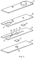
- Such a sample analysis device comprising laminated films can be produced, for example, by laminating films 11, 12, 13 and 14 which are formed into various shapes with the reagent film 7 and the hydrophobic porous film 8 therebetween as shown in Figure 2.
- the film 14 is prepared to form the back side of the sample analysis device, and the window 10 is formed therein.
- cut-out portions for forming the liquid pooling portion 9, the air vent passage 25, the analysis section 3 and the drawing channel 2 are formed.
- the film 12 is prepared to ensure the thickness of the liquid pooling portion 9 (the size of the cross section of the passage), and a cut-out portion for forming the liquid pooling portion 9, a circular cut-out portion for making the end of the air vent channel 25 open, and a circular cut-out portion for leading the drawing channel 2b to the suction generating chamber 1 are formed in the film.
- an approximately cylindrical convex portion for forming the suction generating chamber 1 is formed as a protrusion, and a circular cut-out portion for making the end of the air vent passage 25 open is also formed.
- the reagent film 7 is placed between the film 14 and the film 13 in a position to form the analysis section 3, and the hydrophobic porous film 8 is placed between the film 13 and the film 12 in a position to be a certain place in the drawing channel 2b, and in this state, the four films 14, 13, 12 and 11 are laminated in this order from the bottom and integrated together, so that the sample analysis device shown in Figure 1 can be produced.
- hydrophobic porous film is hydrophobic resin porous film, and particular examples are polyethylene porous film, polypropylene porous film, polytetrafluoroethylene (PTFE) porous film, and the like.
- suitable hydrophobic resin porous film in the present invention include Celgard (product name; produced by Hoechst Celanese Co., Ltd.), and Hipore (product name; produced by Asahi Chemical Industry Co., Ltd.).
- the average diameter of the pores in the hydrophobic resin porous film is usually from 0.1 to 1 ⁇ m, preferably from 0.3 to 0.7 ⁇ m.
- the thickness of the hydrophobic resin porous film is usually from 10 to 100 ⁇ m.
- Such a hydrophobic resin porous film can be produced, for example, by forming a film using said hydrophobic resin and then orienting the film either uniaxially or biaxially.
- the reagent film 7 is prepared by impregnating a film with a reagent, and the type of the reagent is selected as appropriate depending on the type of the object to be analyzed.
- the structure of the reagent film is also determined as appropriate depending on the type of the object for analysis.
- the reagent film used usually comprises a filtration layer for separating erythrocytes, a reagent layer impregnated with a reagent, and a base material, which are laminated in this order.
- the reagent film 7 is arranged in the analysis section 3 in such a manner that the filtration layer can contact with blood (a liquid sample).
- conventionally known materials can be used for the respective layers in the reagent film.
- the films may be integrated together by bonding the films to each other with an adhesive, or by laminating by pressing or heating.
- examples of the materials for the films constituting the sample analysis device include polyethylene, polyethylene terephthalate (PET), polystyrene, polyvinyl chloride, and the like.
- PET is preferably used because of its good processibility.
- the dimensions of the sample analysis device shown in Figure 1 are as follows.
- the overall size of the device is usually 15 to 60 mm in length, 5 to 20 mm in width and 1 to 3 mm in thickness.
- the size of the suction generating chamber 1 is usually 3 to 15 mm in diameter and 0.5 to 3 mm in height.
- the size of the drawing channel 2 is usually 10 to 40 mm in overall length, 0.5 to 2 mm in width and 0.1 to 0.5 mm in thickness; and usually, the drawing channel 2a is 5 to 30 mm in length, and the drawing channel 2b is 5 to 30 mm in length.
- the size of the analysis section 3 is usually 2 to 10 mm in diameter and 0.1 to 1 mm in height.
- the size of the liquid pooling section 9 is usually 2 to 10 mm in length, 2 to 10 mm in width, and 0.2 to 1 mm in thickness.
- the size of the air vent passage 25 is usually 2 to 10 mm in overall length, 0.5 to 2 mm in width and 0.1 to 0.5 mm in thickness; and the opening thereof is usually 0.5 to 5 mm in diameter.
- the size of the suction opening 4 is usually 2 to 10 mm in width and 0.2 to 1 mm in thickness.
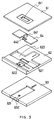
- FIG. 3 is an exploded perspective view of the above-mentioned device.
- this device comprises four parts, namely, a cover plate 61, a middle plate 62, a bottom plate 63 and an operation plate 64.
- a protruding portion 642 for compressing the suction generating chamber is formed in an approximately center portion on the lower side of the operation plate 64, and a protruding portion 641 (a finger grip) for operation is formed in an approximately center portion on the upper side of the operation plate 64.
- a cavity 631 for inserting the sample analysis device therein is formed in an approximately center portion in the bottom plate 63, and a hole 632 for light irradiation is punched in a determined portion in the cavity 631.
- the hole 632 is formed in a position that will correspond to the analysis section 3 when the sample analysis device is inserted into the cavity.
- a concave portion 623 for fitting the operation plate 64 therein is formed in the middle plate 62, and a window section 621 is formed in the center portion of the concave portion 623 to let the lower protruding portion 642 on the operation plate 64 protrude therethrough.
- an open section 622 for placing a detector such as an optical sensor is formed in the middle plate 62.
- a window section 611 is formed in the cover plate 61 to let the upper protruding portion 641 on the operation plate 64 protrude therethrough.
- the dimensions of this device are determined as appropriate depending on the size of the sample analysis device used. For example, when it is applied to the above-mentioned sample analysis device, the dimensions are as follows: First, the size of the bottom plate 63 is usually 2 to 10 mm in thickness; the cavity 631 is usually 5 to 20 mm in width, 1 to 5 mm in depth and 20 to 60 mm in length; and the size of the hole 632 is usually 2 to 10 mm in diameter.
- the size of the operation plate 64 is usually 15 to 50 mm in length, 5 to 20 mm in width and 1 to 10 mm in thickness; and usually, the upper protruding portion 641 is 2 to 5 mm in height, and the lower protruding portion 642 is 1 to 5 mm in height.
- the size of the middle plate 62 is usually 20 to 60 mm in length, 20 to 60 mm in width and 1 to 5 mm in thickness; the size of the concave portion for positioning the operation plate 64 is usually 20 to 70 mm in length and 5 to 20 mm in width; the size of the window section 621 formed in the concave portion is usually 10 to 30 mm in length and 3 to 10 mm in width.
- the size of the cover plate 61 is usually 20 to 60 mm in length, 20 to 60 mm in width and 1 to 5 mm in thickness; and the size of the window section 611 for letting the upper protruding portion 641 on the operation plate 64 protrude therethrough is usually 10 to 30 mm in length and 3 to 10 mm in width.
- the materials for forming this device are not particularly limited, and for example, the operation plate 64 is made of metals such as aluminum, iron, brass, or the like.
- the materials used for forming other parts include acrylonitrile-styrene-butadiene copolymer (ABS resin), polyacetal resin, acrylic resin, vinyl chloride resin, and the like.
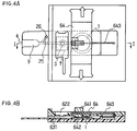
- Figure 4 shows the assembly of this device, in which the sample analysis device (for reference, see Figure 1) is inserted.
- Figure 4 (A) is a plan view of the device
- Figure 4 (B) is a cross-sectional view taken along the line I ⁇ I of Figure 4 (A).
- 643 refers to a wire type spring for positioning the lower protruding portion 642 formed on the operation plate 64 continuously in the center of the cavity.
- the operation plate 64 is capable of sliding in vertical direction relative to the cavity 631 (i.e. upwards or downwards direction as shown with the arrows in the drawing), so that the lower protruding portion 642 can be moved.
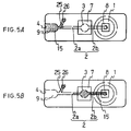
- the sample 15 cannot flow into the suction generating chamber 1, so that introduction of the sample into the analysis section 3 is ensured. Furthermore, in the analysis section 3, reaction occurs between the sample 15 and the reagent in the reagent film 7 to generate a pigment, which develops a color in the reagent film 7. Then, light is irradiated through the window 10 in the lower surface of the sample analysis device, and in case of the above-mentioned densitometry, reflected light is detected at the detecting section and the degree of the color is measured.
- the whole analysis section 3 is transparent and the reagent film 7 is also transparent, analysis can be performed with transmitted light as well. Furthermore, as the sample analysis device is pulled out of the device, the operation plate 64 is automatically returned to its original position by the wire type spring 643.
- Figure 6 shows a cross-sectional view illustrating an example of a sample analysis device, in which an air vent hole is formed in the suction generating chamber.
- the sample analysis device has the same structure as the sample analysis device described in Example 1 shown in Figure 1, except that an air vent hole 1a is formed in the device. Therefore, the same parts are designated with the same reference numerals.
- the size of the air vent hole 1a is usually in the range of 0.1 to 5 mm in diameter.
- Figure 7 shows cross-sectional views illustrating an example of the structure of a second embodiment of the present invention which is used with the sample analysis device, and an example of its use.
- the device has a cavity 66, and two protruding portions 67a and 67b formed in certain positions inside the cavity.
- the size of the device varies depending on the type of the sample analysis device used. For example, when it is applied to the sample analysis device shown in Figure 6, the size of the cavity 66 is usually 20 to 60 mm in length, 2 to 10 mm in height and 5 to 20 mm in width; and usually, the protruding portion 67a is 0.5 to 9 mm in height, and the protruding portion 67b is 0.5 to 9 mm in height.
- the materials for forming the device are the same as mentioned above.
- the device is used, for example, as follows: First, the suction opening 4 of the sample analysis device is brought into contact with a sample 15, and the sample 15 is held in the liquid pooling portion 9. Then, in a first stage of insertion, the sample analysis device is inserted into the cavity 66 as shown in Figure 7(B) so that the suction generating chamber is compressed by the protruding portion 67a. During this stage, because the air contained in the suction generating chamber 1 escapes from the air vent hole 1a, the sample is not discharged from the opening 4 by the pressure of the air from the suction generating chamber 1.
- the sample analysis device is inserted deeper into the cavity 66 so that the chamber is released from the compression by the protruding portion 67a ( Figure 7 (C)), while the air vent hole 1a is closed with the protruding portion 67b ( Figure 7 (D)).
- suction is developed as the compressed suction generating chamber is released to return to its original shape, thereby moving the sample 15 through the drawing channel 2 and into the analysis section 3 ( Figure 7 (D)).
- the suction force that is developed in the suction generating chamber displays its effect in the drawing channel, thereby drawing the sample through the channel.
- the subsequent operation is the same as described above.
- the two-stage process of the insertion of the sample analysis device into the cavity of this suction generating device can be carried out either in one step or in two steps. If the sample analysis device is inserted in two steps, the process becomes as follows: In the first step, the insertion is continued until the suction generating chamber is compressed, and then it is stopped for a while, and in this state, the opening is brought into contact with a sample so that the sample is drawn into the liquid pooling portion by capillarity and is held therein, and then, in the second step, the device is inserted deeper into the cavity and suction is generated, thereby transferring the sample into the analysis section.
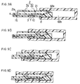
- the sample analysis device is the same as the device shown in Figure 1 except that it has a suction generating tube 21 in place of a suction generating chamber, so that the same parts are designated by the same reference numerals.
- the suction generating tube 21 can be formed, for example, by positioning a resin sheet, which is bent in a manner so that its cross section in the longitudinal direction becomes an approximately reverse U-shape, on the body of the sample analysis device. In this case, one end of the suction generating tube communicates with the drawing channel 2 through the gas-permeable liquid-impermeable stopper 8, and the other end of the tube is open (opening 21a).
- the size of the suction generating tube is usually as follows:
- the thickness of the sheet is in the range of 0.01 to 2 mm
- the height inside the tube is in the range of 0.5 to 5 mm
- the width inside the tube is in the range of 1 to 10 mm
- the length of the tube is in the range of 5 to 30 mm.
- the suction generating tube 21 is preferably formed in such a manner that it does not overlap with the drawing channel 2, the analysis section 3, or the like. This is because, in order to develop suction in suction generating tube 21, it is required to draw the tube through by pressing. However, this pressing might cause deformation of the drawing channel, or the like.
- the materials for forming the resin sheet include soft vinyl chloride resin, soft silicon resin, natural rubber, and the like.
- the shape of the cross section of the suction generating tube in the longitudinal direction is not limited to the reverse U-shape, and for example, it may be rectangular, or the like.
- the device has a cavity 68b, and a protruding portion 68a formed near the opening of the cavity 68b.
- the size of the device varies depending on the type of the sample analysis device used. For example, if it is applied to the sample analysis device shown in Figure 8, the size of the cavity 68b is usually 20 to 60 mm in length, 2 to 10 mm in height, and 5 to 20 mm in width; and the protruding portion 68a is usually 0.5 to 9 mm in height. Furthermore, the materials for forming the device are the same as mentioned above.
- This device is used, for example, as follows: First, the suction opening 4 of the sample analysis device is brought into contact with a sample 15, and the sample 15 is held in the liquid pooling portion 9. Then, as shown in Figure 9(B), as the sample analysis device is inserted into the cavity 68b, the suction generating tube 21 is pressed in the portion in communication with the drawing channel 2. Then, as shown in Figures 9 (B), (C) and (D) in order, as the sample analysis device is inserted deeper into the cavity, the suction generating tube 21 is sequentially deformed by the protruding portion 68a to develop suction, and the sample 15 is thereby moved through the drawing channel 2 and introduced into the analysis section 3. The subsequent analysis operation is the same as in the above-mentioned Examples.
Landscapes
- Health & Medical Sciences (AREA)
- Life Sciences & Earth Sciences (AREA)
- General Health & Medical Sciences (AREA)
- Hematology (AREA)
- Molecular Biology (AREA)
- Public Health (AREA)
- Biophysics (AREA)
- Pathology (AREA)
- Engineering & Computer Science (AREA)
- Biomedical Technology (AREA)
- Heart & Thoracic Surgery (AREA)
- Medical Informatics (AREA)
- Veterinary Medicine (AREA)
- Surgery (AREA)
- Animal Behavior & Ethology (AREA)
- Physics & Mathematics (AREA)
- Dermatology (AREA)
- Chemical & Material Sciences (AREA)
- Pain & Pain Management (AREA)
- Analytical Chemistry (AREA)
- Clinical Laboratory Science (AREA)
- Chemical Kinetics & Catalysis (AREA)
- Sampling And Sample Adjustment (AREA)
- Investigating Or Analysing Biological Materials (AREA)
- Measurement Of The Respiration, Hearing Ability, Form, And Blood Characteristics Of Living Organisms (AREA)
- Analysing Materials By The Use Of Radiation (AREA)
- Load-Engaging Elements For Cranes (AREA)
Applications Claiming Priority (3)
| Application Number | Priority Date | Filing Date | Title |
|---|---|---|---|
| JP23150697A JP3498201B2 (ja) | 1997-08-27 | 1997-08-27 | 引圧発生装置およびそれを用いた検体分析装置 |
| JP23150697 | 1997-08-27 | ||
| JP231506/97 | 1997-08-27 |
Publications (3)
| Publication Number | Publication Date |
|---|---|
| EP0903180A2 true EP0903180A2 (fr) | 1999-03-24 |
| EP0903180A3 EP0903180A3 (fr) | 2000-03-22 |
| EP0903180B1 EP0903180B1 (fr) | 2004-07-21 |
Family
ID=16924569
Family Applications (1)
| Application Number | Title | Priority Date | Filing Date |
|---|---|---|---|
| EP98306900A Expired - Lifetime EP0903180B1 (fr) | 1997-08-27 | 1998-08-27 | Dispositif d'aspiration, et dispositif d'analyse d'échantillons l'utilisant |
Country Status (5)
| Country | Link |
|---|---|
| US (1) | US6325975B1 (fr) |
| EP (1) | EP0903180B1 (fr) |
| JP (1) | JP3498201B2 (fr) |
| AT (1) | ATE271421T1 (fr) |
| DE (1) | DE69825107T2 (fr) |
Cited By (17)
| Publication number | Priority date | Publication date | Assignee | Title |
|---|---|---|---|---|
| WO2001051205A1 (fr) * | 2000-01-13 | 2001-07-19 | Meinhard Knoll | Analyse quantitative optique ou electrochimique d'echantillons liquides |
| EP0990900A3 (fr) * | 1998-09-29 | 2001-09-26 | CASTELLINI S.p.A. | Méthode et appareil de détection d'éléments biologiques sur un patient, à utiliser en particulier en chirurgie médicale-dentaire |
| US6482006B2 (en) | 2000-03-31 | 2002-11-19 | Castellini S.P.A. | Unit for detecting contaminating agents, especially in dental surgeries, and a dental unit equipped with such a detecting unit |
| EP1267165A1 (fr) * | 2001-06-13 | 2002-12-18 | CASTELLINI S.p.A. | Système pour la détection d'agents contaminants dans la cavité orale et unité dentaire comportant un tel système |
| DE10222478A1 (de) * | 2002-05-22 | 2003-12-04 | Bartels Mikrotechnik Gmbh | Verteilelement für Flüssigkeiten und Gase, Lab-on-a-Cip, Lab-on-a-Card |
| DE10354806A1 (de) * | 2003-11-21 | 2005-06-02 | Boehringer Ingelheim Microparts Gmbh | Probenträger |
| US7005109B2 (en) | 1999-07-15 | 2006-02-28 | Eppendorf Ag | System for handling liquid samples |
| GB2453744A (en) * | 2007-10-16 | 2009-04-22 | Porvair Filtration Group Ltd | Testing apparatus and method with dosing mechanism |
| WO2011007309A1 (fr) * | 2009-07-17 | 2011-01-20 | Koninklijke Philips Electronics N.V. | Système d'actionnement de fluide |
| WO2017001922A1 (fr) * | 2015-07-02 | 2017-01-05 | Marc Andrew Koska | Dispositif de prélèvement d'échantillon biologique |
| EP3572789A1 (fr) * | 2005-11-04 | 2019-11-27 | Alere Technologies GmbH | Dispositif et procédé de détection de particules |
| US10835678B2 (en) | 2015-07-02 | 2020-11-17 | Koska Family Limited | Single use delivery device prefilled with a reconstitutable agent |
| US11382833B2 (en) | 2016-04-25 | 2022-07-12 | Koska Family Limited | Systems and methods for fluid delivery |
| US11607369B2 (en) | 2017-11-17 | 2023-03-21 | Koska Family Limited | Systems and methods for fluid delivery manifolds |
| USD992110S1 (en) | 2021-08-10 | 2023-07-11 | Koska Family Limited | Sealed fluid container |
| USD1052082S1 (en) | 2020-06-01 | 2024-11-19 | Koska Family Limited | Sealed fluid container |
| US12544511B2 (en) | 2018-06-20 | 2026-02-10 | Koska Family Limited | Systems and methods for pre-filled dual-chamber medical agent delivery |
Families Citing this family (45)
| Publication number | Priority date | Publication date | Assignee | Title |
|---|---|---|---|---|
| US5959098A (en) | 1996-04-17 | 1999-09-28 | Affymetrix, Inc. | Substrate preparation process |
| DE19753847A1 (de) | 1997-12-04 | 1999-06-10 | Roche Diagnostics Gmbh | Analytisches Testelement mit Kapillarkanal |
| DE19753850A1 (de) | 1997-12-04 | 1999-06-10 | Roche Diagnostics Gmbh | Probennahmevorrichtung |
| US6521182B1 (en) * | 1998-07-20 | 2003-02-18 | Lifescan, Inc. | Fluidic device for medical diagnostics |
| US6612111B1 (en) * | 2000-03-27 | 2003-09-02 | Lifescan, Inc. | Method and device for sampling and analyzing interstitial fluid and whole blood samples |
| US6908593B1 (en) * | 2000-03-31 | 2005-06-21 | Lifescan, Inc. | Capillary flow control in a fluidic diagnostic device |
| US6652814B1 (en) * | 2000-08-11 | 2003-11-25 | Lifescan, Inc. | Strip holder for use in a test strip meter |
| US6713023B2 (en) * | 2001-06-29 | 2004-03-30 | Agilent Technologies, Inc. | Flow cell for chemical reactions |
| US6660527B2 (en) * | 2002-03-28 | 2003-12-09 | David Karl Stroup | Fluid-transfer collection assembly and method of using the same |
| JPWO2004113927A1 (ja) * | 2003-06-19 | 2006-08-24 | アークレイ株式会社 | 液溜部を備えた分析用具 |
| US20050178218A1 (en) * | 2004-01-28 | 2005-08-18 | Jean Montagu | Micro-volume blood sampling device |
| US7802467B2 (en) | 2006-12-22 | 2010-09-28 | Abbott Diabetes Care Inc. | Analyte sensors and methods of use |
| WO2009037810A1 (fr) * | 2007-09-18 | 2009-03-26 | Panasonic Corporation | Dispositif de mesure, instrument et procédé de mesure, et procédé d'échantillonnage |
| JP5234749B2 (ja) * | 2007-12-27 | 2013-07-10 | 株式会社堀場製作所 | 被検液分析用チップ |
| WO2010025282A2 (fr) | 2008-08-29 | 2010-03-04 | Infusion Innnovations, Inc | Ensemble de prélèvement à transfert de fluide sans soupape de retenue et son procédé d'utilisation |
| KR101763119B1 (ko) * | 2009-04-13 | 2017-07-31 | 마이크로닉스 인코포레이티드. | 미세유체 임상 분석기 |
| CA2786569C (fr) | 2010-01-29 | 2019-04-09 | Perkinelmer Health Sciences, Inc. | Cartouche microfluidique «de l'echantillon au resultat» |
| US8535241B2 (en) | 2011-10-13 | 2013-09-17 | Magnolia Medical Technologies, Inc. | Fluid diversion mechanism for bodily-fluid sampling |
| US9022950B2 (en) | 2012-05-30 | 2015-05-05 | Magnolia Medical Technologies, Inc. | Fluid diversion mechanism for bodily-fluid sampling |
| US9060724B2 (en) | 2012-05-30 | 2015-06-23 | Magnolia Medical Technologies, Inc. | Fluid diversion mechanism for bodily-fluid sampling |
| WO2014022275A1 (fr) | 2012-08-01 | 2014-02-06 | Magnolia Medical Technologies, Inc. | Mécanisme de déviation de fluide pour prélèvement de fluide corporel |
| WO2014058945A1 (fr) | 2012-10-11 | 2014-04-17 | Bullington Gregory J | Systèmes et méthodes d'administration d'un fluide à un patient en réduisant la contamination |
| CN109171766A (zh) | 2012-11-30 | 2019-01-11 | 木兰医药技术股份有限公司 | 体液隔绝装置和使用体液隔绝装置隔绝体液的方法 |
| IL303591B2 (en) | 2012-12-04 | 2025-11-01 | Magnolia Medical Technologies Inc | Sterile bodily-fluid collection device and methods |
| US10772548B2 (en) | 2012-12-04 | 2020-09-15 | Magnolia Medical Technologies, Inc. | Sterile bodily-fluid collection device and methods |
| JP6498125B2 (ja) | 2012-12-21 | 2019-04-10 | マイクロニクス, インコーポレイテッド | 流体回路および関連する製造方法 |
| CN104919035B (zh) | 2012-12-21 | 2017-08-11 | 精密公司 | 便携式荧光检测系统和微测定盒 |
| KR20150096788A (ko) | 2012-12-21 | 2015-08-25 | 마이크로닉스 인코포레이티드. | 마이크로 유체공학 용도를 위한 저탄성 막 |
| WO2014182844A1 (fr) | 2013-05-07 | 2014-11-13 | Micronics, Inc. | Dispositifs microfluidiques et méthodes de séparation du sérum et de compatibilité croisée du sang |
| CA2911303C (fr) | 2013-05-07 | 2021-02-16 | Micronics, Inc. | Procedes de preparation d'echantillons d'acides nucleiques faisant appel a des mineraux argileux et a des solutions alcalines |
| EP2994543B1 (fr) | 2013-05-07 | 2018-08-15 | Micronics, Inc. | Dispositif pour la préparation et l'analyse d'acides nucléiques |
| JP2016532090A (ja) * | 2013-09-26 | 2016-10-13 | クイック エルエルシー | 光学分析のためのサンプル収集デバイス |
| EP3307359B1 (fr) | 2015-06-12 | 2020-07-01 | Gregory J. Bullington | Appareil pour transfert de fluide par seringue pour échantillonnage de fluide corporel |
| EP3733067B1 (fr) | 2015-09-03 | 2023-06-14 | Magnolia Medical Technologies, Inc. | Système de maintien de la stérilité d'un récipient d'échantillon |
| JP6876897B2 (ja) * | 2015-09-18 | 2021-05-26 | イービーエム株式会社 | 血流解析装置、その方法、及びそのコンピュータソフトウェアプログラム |
| DE102016222040A1 (de) * | 2016-11-10 | 2018-05-17 | Robert Bosch Gmbh | Mikrofluidische Vorrichtung |
| JP7273807B2 (ja) | 2017-06-09 | 2023-05-15 | マグノリア メディカル テクノロジーズ,インコーポレイテッド | 流体制御デバイス及びそれを使用する方法 |
| EP3681384B1 (fr) | 2017-09-12 | 2022-12-28 | Magnolia Medical Technologies, Inc. | Un système |
| US11419531B2 (en) | 2017-12-07 | 2022-08-23 | Magnolia Medical Technologies, Inc. | Fluid control devices and methods of using the same |
| JP6677273B2 (ja) * | 2018-05-31 | 2020-04-08 | 佳則 山口 | マイクロサンプリングチップ及びそのマイクロサンプリングチップを用いる検査装置 |
| JP7064069B2 (ja) * | 2018-12-10 | 2022-05-10 | テクノグローバル株式会社 | マイクロサンプリングチップ |
| WO2020163744A1 (fr) | 2019-02-08 | 2020-08-13 | Magnolia Medical Technologies, Inc. | Dispositifs et procédés pour la collecte et la distribution de fluide corporel |
| AU2020234829B2 (en) | 2019-03-11 | 2025-11-13 | Magnolia Medical Technologies, Inc. | Fluid control devices and methods of using the same |
| WO2020214224A1 (fr) * | 2019-04-18 | 2020-10-22 | Siemens Healthcare Diagnostics Inc. | Dispositif microfluidique intégré avec adaptation de pipette |
| CN116698765B (zh) * | 2023-06-19 | 2025-11-14 | 凤阳常隆科技材料有限公司 | 一种基于水玻璃自动化生产的成品色度监控装置 |
Family Cites Families (22)
| Publication number | Priority date | Publication date | Assignee | Title |
|---|---|---|---|---|
| US3620676A (en) | 1969-02-20 | 1971-11-16 | Sterilizer Control Royalties A | Disposable colorimetric indicator and sampling device for liquids |
| SE399768B (sv) | 1975-09-29 | 1978-02-27 | Lilja Jan E | Kyvett for provtagning, blandning av, provet med ett reagensmedel och direkt utforande av, serskilt optisk, analys av det med reagensmedlet blandade provet |
| US4065263A (en) | 1976-04-02 | 1977-12-27 | Woodbridge Iii Richard G | Analytical test strip apparatus |
| US4195526A (en) | 1978-02-09 | 1980-04-01 | Corning Glass Works | Hand-held pipetter |
| GB2090659A (en) | 1981-01-02 | 1982-07-14 | Instrumentation Labor Inc | Analytical device |
| US4624928A (en) | 1984-11-01 | 1986-11-25 | Allied Corporation | Liquid handling process |
| US4650662A (en) | 1984-11-13 | 1987-03-17 | Cedars-Sinai Medical Center | Portable blood typing apparatus and method |
| JPH0658338B2 (ja) | 1988-05-18 | 1994-08-03 | 松下電器産業株式会社 | バイオセンサ |
| EP0359831B2 (fr) | 1988-03-31 | 2007-06-20 | Matsushita Electric Industrial Co., Ltd. | Biocapteur et procede de production |
| US5188455A (en) * | 1990-11-13 | 1993-02-23 | The Pennsylvania Research Corporation | Apparatus for remote mixing of fluids |
| JPH04188065A (ja) | 1990-11-21 | 1992-07-06 | Kyoto Daiichi Kagaku:Kk | 液体試料分析用具および分析方法 |
| US5192415A (en) | 1991-03-04 | 1993-03-09 | Matsushita Electric Industrial Co., Ltd. | Biosensor utilizing enzyme and a method for producing the same |
| US5264103A (en) | 1991-10-18 | 1993-11-23 | Matsushita Electric Industrial Co., Ltd. | Biosensor and a method for measuring a concentration of a substrate in a sample |
| US5262037A (en) | 1992-05-22 | 1993-11-16 | Biomedical Sensors, Ltd. | Electrochemical sensor |
| US5354448A (en) | 1992-05-22 | 1994-10-11 | Biomedical Sensors Ltd. | Electrochemical sensor |
| US5387327A (en) | 1992-10-19 | 1995-02-07 | Duquesne University Of The Holy Ghost | Implantable non-enzymatic electrochemical glucose sensor |
| FR2710411B1 (fr) | 1993-09-21 | 1995-11-17 | Asulab Sa | Dispositif de mesure pour capteurs multizones amovibles. |
| JP3027306B2 (ja) | 1994-06-02 | 2000-04-04 | 松下電器産業株式会社 | バイオセンサおよびその製造方法 |
| US5700695A (en) | 1994-06-30 | 1997-12-23 | Zia Yassinzadeh | Sample collection and manipulation method |
| CA2156226C (fr) | 1994-08-25 | 1999-02-23 | Takayuki Taguchi | Dispositif et methode d'analyse pour fluide biologique |
| US5582697A (en) | 1995-03-17 | 1996-12-10 | Matsushita Electric Industrial Co., Ltd. | Biosensor, and a method and a device for quantifying a substrate in a sample liquid using the same |
| US6001307A (en) * | 1996-04-26 | 1999-12-14 | Kyoto Daiichi Kagaku Co., Ltd. | Device for analyzing a sample |
-
1997
- 1997-08-27 JP JP23150697A patent/JP3498201B2/ja not_active Expired - Lifetime
-
1998
- 1998-08-20 US US09/137,169 patent/US6325975B1/en not_active Expired - Lifetime
- 1998-08-27 AT AT98306900T patent/ATE271421T1/de not_active IP Right Cessation
- 1998-08-27 DE DE69825107T patent/DE69825107T2/de not_active Expired - Lifetime
- 1998-08-27 EP EP98306900A patent/EP0903180B1/fr not_active Expired - Lifetime
Cited By (25)
| Publication number | Priority date | Publication date | Assignee | Title |
|---|---|---|---|---|
| EP0990900A3 (fr) * | 1998-09-29 | 2001-09-26 | CASTELLINI S.p.A. | Méthode et appareil de détection d'éléments biologiques sur un patient, à utiliser en particulier en chirurgie médicale-dentaire |
| DE19933458B4 (de) * | 1999-07-15 | 2015-08-20 | Eppendorf Ag | Einrichtungen und Systeme zum Handhaben von Flüssigkeitsproben |
| US7005109B2 (en) | 1999-07-15 | 2006-02-28 | Eppendorf Ag | System for handling liquid samples |
| DE10001116C2 (de) * | 2000-01-13 | 2002-11-28 | Meinhard Knoll | Vorrichtung und Verfahren zur optischen oder elektrochemischen quantitativen Bestimmung chemischer oder biochemischer Substanzen in flüssigen Proben |
| WO2001051205A1 (fr) * | 2000-01-13 | 2001-07-19 | Meinhard Knoll | Analyse quantitative optique ou electrochimique d'echantillons liquides |
| US6482006B2 (en) | 2000-03-31 | 2002-11-19 | Castellini S.P.A. | Unit for detecting contaminating agents, especially in dental surgeries, and a dental unit equipped with such a detecting unit |
| EP1267165A1 (fr) * | 2001-06-13 | 2002-12-18 | CASTELLINI S.p.A. | Système pour la détection d'agents contaminants dans la cavité orale et unité dentaire comportant un tel système |
| DE10222478A1 (de) * | 2002-05-22 | 2003-12-04 | Bartels Mikrotechnik Gmbh | Verteilelement für Flüssigkeiten und Gase, Lab-on-a-Cip, Lab-on-a-Card |
| DE10354806A1 (de) * | 2003-11-21 | 2005-06-02 | Boehringer Ingelheim Microparts Gmbh | Probenträger |
| US7829027B2 (en) | 2003-11-21 | 2010-11-09 | Boehringer Ingelheim Microparts Gmbh | Sample carrier |
| EP3572789A1 (fr) * | 2005-11-04 | 2019-11-27 | Alere Technologies GmbH | Dispositif et procédé de détection de particules |
| GB2453744A (en) * | 2007-10-16 | 2009-04-22 | Porvair Filtration Group Ltd | Testing apparatus and method with dosing mechanism |
| GB2453744B (en) * | 2007-10-16 | 2009-10-21 | Porvair Filtration Group Ltd | Testing apparatus and method with dosing mechanism |
| WO2011007309A1 (fr) * | 2009-07-17 | 2011-01-20 | Koninklijke Philips Electronics N.V. | Système d'actionnement de fluide |
| US11786661B2 (en) | 2015-07-02 | 2023-10-17 | Koska Family Limited | Single use delivery device |
| WO2017001922A1 (fr) * | 2015-07-02 | 2017-01-05 | Marc Andrew Koska | Dispositif de prélèvement d'échantillon biologique |
| US10835678B2 (en) | 2015-07-02 | 2020-11-17 | Koska Family Limited | Single use delivery device prefilled with a reconstitutable agent |
| US11382833B2 (en) | 2016-04-25 | 2022-07-12 | Koska Family Limited | Systems and methods for fluid delivery |
| US12059389B2 (en) | 2016-04-25 | 2024-08-13 | Koska Family Limited | Systems and methods for fluid delivery |
| US11607369B2 (en) | 2017-11-17 | 2023-03-21 | Koska Family Limited | Systems and methods for fluid delivery manifolds |
| US12336959B2 (en) | 2017-11-17 | 2025-06-24 | Koska Family Limited | Systems and methods for fluid delivery manifolds |
| US12544511B2 (en) | 2018-06-20 | 2026-02-10 | Koska Family Limited | Systems and methods for pre-filled dual-chamber medical agent delivery |
| USD1052082S1 (en) | 2020-06-01 | 2024-11-19 | Koska Family Limited | Sealed fluid container |
| USD1116097S1 (en) | 2020-06-01 | 2026-03-03 | Koska Family Limited | Sealed fluid container |
| USD992110S1 (en) | 2021-08-10 | 2023-07-11 | Koska Family Limited | Sealed fluid container |
Also Published As
| Publication number | Publication date |
|---|---|
| JPH1156821A (ja) | 1999-03-02 |
| JP3498201B2 (ja) | 2004-02-16 |
| DE69825107T2 (de) | 2005-07-28 |
| EP0903180A3 (fr) | 2000-03-22 |
| EP0903180B1 (fr) | 2004-07-21 |
| DE69825107D1 (de) | 2004-08-26 |
| ATE271421T1 (de) | 2004-08-15 |
| US6325975B1 (en) | 2001-12-04 |
Similar Documents
| Publication | Publication Date | Title |
|---|---|---|
| EP0903180B1 (fr) | Dispositif d'aspiration, et dispositif d'analyse d'échantillons l'utilisant | |
| US6991762B1 (en) | Device for analyzing a sample | |
| EP1240945B1 (fr) | Dispositif et procédé pour l'analyse d'un échantillon | |
| US5096669A (en) | Disposable sensing device for real time fluid analysis | |
| CA2267919C (fr) | Procede de fabrication de dispositifs analytiques | |
| EP0830206B1 (fr) | Porte-bandelette d'essai et son procede d'utilisation | |
| HK1007797B (en) | Disposable sensing device for real time fluid analysis | |
| US4308028A (en) | Device and method for the chemical testing and microscopic examination of liquid specimens | |
| US5916522A (en) | Electrochemical analytical cartridge | |
| EP1404232B1 (fr) | Appareil de prelevement sanguin et procede connexe | |
| JP4889743B2 (ja) | 流体サンプル中のアナライトを検出するための装置 | |
| CA2524812C (fr) | Systeme pour l'analyse d'un echantillon de liquide sur un element d'essai analytique | |
| JP2937568B2 (ja) | 自己計測式流体分析器具 | |
| AU2157699A (en) | Capillary active test element having an intermediate layer situated between the support and the covering | |
| US7510682B2 (en) | Test element analysis system | |
| JP4979005B2 (ja) | バイオセンサ測定装置 | |
| JP3460142B2 (ja) | 余剰液溜めを有する毛細管により液体試料を分析する試験具 | |
| JP3527980B2 (ja) | 複数の排気口を有する毛細管により液体試料を分析する試験具 | |
| HK1073886A (en) | Diagnostic test strip for collecting and detecting an analyte in a fluid sample and method for using same |
Legal Events
| Date | Code | Title | Description |
|---|---|---|---|
| PUAI | Public reference made under article 153(3) epc to a published international application that has entered the european phase |
Free format text: ORIGINAL CODE: 0009012 |
|
| AK | Designated contracting states |
Kind code of ref document: A2 Designated state(s): AT BE CH CY DE DK ES FI FR GB GR IE IT LI LU MC NL PT SE |
|
| AX | Request for extension of the european patent |
Free format text: AL;LT;LV;MK;RO;SI |
|
| PUAL | Search report despatched |
Free format text: ORIGINAL CODE: 0009013 |
|
| AK | Designated contracting states |
Kind code of ref document: A3 Designated state(s): AT BE CH CY DE DK ES FI FR GB GR IE IT LI LU MC NL PT SE |
|
| AX | Request for extension of the european patent |
Free format text: AL;LT;LV;MK;RO;SI |
|
| 17P | Request for examination filed |
Effective date: 20000529 |
|
| AKX | Designation fees paid |
Free format text: AT BE CH CY DE DK ES FI FR GB GR IE IT LI LU MC NL PT SE |
|
| 17Q | First examination report despatched |
Effective date: 20030507 |
|
| GRAP | Despatch of communication of intention to grant a patent |
Free format text: ORIGINAL CODE: EPIDOSNIGR1 |
|
| GRAS | Grant fee paid |
Free format text: ORIGINAL CODE: EPIDOSNIGR3 |
|
| GRAA | (expected) grant |
Free format text: ORIGINAL CODE: 0009210 |
|
| RAP1 | Party data changed (applicant data changed or rights of an application transferred) |
Owner name: ARKRAY, INC. |
|
| AK | Designated contracting states |
Kind code of ref document: B1 Designated state(s): AT BE CH CY DE DK ES FI FR GB GR IE IT LI LU MC NL PT SE |
|
| PG25 | Lapsed in a contracting state [announced via postgrant information from national office to epo] |
Ref country code: NL Free format text: LAPSE BECAUSE OF FAILURE TO SUBMIT A TRANSLATION OF THE DESCRIPTION OR TO PAY THE FEE WITHIN THE PRESCRIBED TIME-LIMIT Effective date: 20040721 Ref country code: LI Free format text: LAPSE BECAUSE OF FAILURE TO SUBMIT A TRANSLATION OF THE DESCRIPTION OR TO PAY THE FEE WITHIN THE PRESCRIBED TIME-LIMIT Effective date: 20040721 Ref country code: FI Free format text: LAPSE BECAUSE OF FAILURE TO SUBMIT A TRANSLATION OF THE DESCRIPTION OR TO PAY THE FEE WITHIN THE PRESCRIBED TIME-LIMIT Effective date: 20040721 Ref country code: CY Free format text: LAPSE BECAUSE OF FAILURE TO SUBMIT A TRANSLATION OF THE DESCRIPTION OR TO PAY THE FEE WITHIN THE PRESCRIBED TIME-LIMIT Effective date: 20040721 Ref country code: CH Free format text: LAPSE BECAUSE OF FAILURE TO SUBMIT A TRANSLATION OF THE DESCRIPTION OR TO PAY THE FEE WITHIN THE PRESCRIBED TIME-LIMIT Effective date: 20040721 Ref country code: BE Free format text: LAPSE BECAUSE OF FAILURE TO SUBMIT A TRANSLATION OF THE DESCRIPTION OR TO PAY THE FEE WITHIN THE PRESCRIBED TIME-LIMIT Effective date: 20040721 Ref country code: AT Free format text: LAPSE BECAUSE OF FAILURE TO SUBMIT A TRANSLATION OF THE DESCRIPTION OR TO PAY THE FEE WITHIN THE PRESCRIBED TIME-LIMIT Effective date: 20040721 |
|
| REG | Reference to a national code |
Ref country code: GB Ref legal event code: FG4D |
|
| REG | Reference to a national code |
Ref country code: CH Ref legal event code: EP |
|
| REG | Reference to a national code |
Ref country code: IE Ref legal event code: FG4D |
|
| REF | Corresponds to: |
Ref document number: 69825107 Country of ref document: DE Date of ref document: 20040826 Kind code of ref document: P |
|
| PG25 | Lapsed in a contracting state [announced via postgrant information from national office to epo] |
Ref country code: LU Free format text: LAPSE BECAUSE OF NON-PAYMENT OF DUE FEES Effective date: 20040827 Ref country code: IE Free format text: LAPSE BECAUSE OF NON-PAYMENT OF DUE FEES Effective date: 20040827 |
|
| PG25 | Lapsed in a contracting state [announced via postgrant information from national office to epo] |
Ref country code: MC Free format text: LAPSE BECAUSE OF NON-PAYMENT OF DUE FEES Effective date: 20040831 |
|
| PG25 | Lapsed in a contracting state [announced via postgrant information from national office to epo] |
Ref country code: SE Free format text: LAPSE BECAUSE OF FAILURE TO SUBMIT A TRANSLATION OF THE DESCRIPTION OR TO PAY THE FEE WITHIN THE PRESCRIBED TIME-LIMIT Effective date: 20041021 Ref country code: GR Free format text: LAPSE BECAUSE OF FAILURE TO SUBMIT A TRANSLATION OF THE DESCRIPTION OR TO PAY THE FEE WITHIN THE PRESCRIBED TIME-LIMIT Effective date: 20041021 Ref country code: DK Free format text: LAPSE BECAUSE OF FAILURE TO SUBMIT A TRANSLATION OF THE DESCRIPTION OR TO PAY THE FEE WITHIN THE PRESCRIBED TIME-LIMIT Effective date: 20041021 |
|
| PG25 | Lapsed in a contracting state [announced via postgrant information from national office to epo] |
Ref country code: ES Free format text: LAPSE BECAUSE OF FAILURE TO SUBMIT A TRANSLATION OF THE DESCRIPTION OR TO PAY THE FEE WITHIN THE PRESCRIBED TIME-LIMIT Effective date: 20041101 |
|
| NLV1 | Nl: lapsed or annulled due to failure to fulfill the requirements of art. 29p and 29m of the patents act | ||
| REG | Reference to a national code |
Ref country code: CH Ref legal event code: PL |
|
| ET | Fr: translation filed | ||
| PLBE | No opposition filed within time limit |
Free format text: ORIGINAL CODE: 0009261 |
|
| STAA | Information on the status of an ep patent application or granted ep patent |
Free format text: STATUS: NO OPPOSITION FILED WITHIN TIME LIMIT |
|
| REG | Reference to a national code |
Ref country code: IE Ref legal event code: MM4A |
|
| 26N | No opposition filed |
Effective date: 20050422 |
|
| PG25 | Lapsed in a contracting state [announced via postgrant information from national office to epo] |
Ref country code: PT Free format text: LAPSE BECAUSE OF NON-PAYMENT OF DUE FEES Effective date: 20041221 |
|
| REG | Reference to a national code |
Ref country code: FR Ref legal event code: PLFP Year of fee payment: 19 |
|
| REG | Reference to a national code |
Ref country code: FR Ref legal event code: PLFP Year of fee payment: 20 |
|
| PGFP | Annual fee paid to national office [announced via postgrant information from national office to epo] |
Ref country code: FR Payment date: 20170822 Year of fee payment: 20 Ref country code: IT Payment date: 20170828 Year of fee payment: 20 Ref country code: DE Payment date: 20170822 Year of fee payment: 20 Ref country code: GB Payment date: 20170822 Year of fee payment: 20 |
|
| REG | Reference to a national code |
Ref country code: DE Ref legal event code: R071 Ref document number: 69825107 Country of ref document: DE |
|
| REG | Reference to a national code |
Ref country code: GB Ref legal event code: PE20 Expiry date: 20180826 |
|
| PG25 | Lapsed in a contracting state [announced via postgrant information from national office to epo] |
Ref country code: GB Free format text: LAPSE BECAUSE OF EXPIRATION OF PROTECTION Effective date: 20180826 |