EP0903183A1 - Appareil de fragmentation et de concassage de gros matériaux - Google Patents
Appareil de fragmentation et de concassage de gros matériaux Download PDFInfo
- Publication number
- EP0903183A1 EP0903183A1 EP98203133A EP98203133A EP0903183A1 EP 0903183 A1 EP0903183 A1 EP 0903183A1 EP 98203133 A EP98203133 A EP 98203133A EP 98203133 A EP98203133 A EP 98203133A EP 0903183 A1 EP0903183 A1 EP 0903183A1
- Authority
- EP
- European Patent Office
- Prior art keywords
- rollers
- roller
- disks
- crushing
- ribs
- Prior art date
- Legal status (The legal status is an assumption and is not a legal conclusion. Google has not performed a legal analysis and makes no representation as to the accuracy of the status listed.)
- Granted
Links
- 239000000463 material Substances 0.000 title claims abstract description 32
- 230000001603 reducing effect Effects 0.000 title claims abstract description 12
- 230000009467 reduction Effects 0.000 claims abstract description 8
- 238000010008 shearing Methods 0.000 claims abstract description 6
- 230000000694 effects Effects 0.000 claims abstract 2
- 238000005192 partition Methods 0.000 claims description 7
- 230000007246 mechanism Effects 0.000 claims description 4
- 230000009471 action Effects 0.000 description 8
- 239000012634 fragment Substances 0.000 description 2
- 238000000034 method Methods 0.000 description 2
- 230000008569 process Effects 0.000 description 2
- 230000007423 decrease Effects 0.000 description 1
- 235000013399 edible fruits Nutrition 0.000 description 1
- 230000002349 favourable effect Effects 0.000 description 1
- 239000010921 garden waste Substances 0.000 description 1
- 230000004048 modification Effects 0.000 description 1
- 238000012986 modification Methods 0.000 description 1
- 230000002093 peripheral effect Effects 0.000 description 1
- 235000013311 vegetables Nutrition 0.000 description 1
Images
Classifications
-
- B—PERFORMING OPERATIONS; TRANSPORTING
- B02—CRUSHING, PULVERISING, OR DISINTEGRATING; PREPARATORY TREATMENT OF GRAIN FOR MILLING
- B02C—CRUSHING, PULVERISING, OR DISINTEGRATING IN GENERAL; MILLING GRAIN
- B02C18/00—Disintegrating by knives or other cutting or tearing members which chop material into fragments
- B02C18/06—Disintegrating by knives or other cutting or tearing members which chop material into fragments with rotating knives
- B02C18/14—Disintegrating by knives or other cutting or tearing members which chop material into fragments with rotating knives within horizontal containers
- B02C18/142—Disintegrating by knives or other cutting or tearing members which chop material into fragments with rotating knives within horizontal containers with two or more inter-engaging rotatable cutter assemblies
-
- B—PERFORMING OPERATIONS; TRANSPORTING
- B02—CRUSHING, PULVERISING, OR DISINTEGRATING; PREPARATORY TREATMENT OF GRAIN FOR MILLING
- B02C—CRUSHING, PULVERISING, OR DISINTEGRATING IN GENERAL; MILLING GRAIN
- B02C19/00—Other disintegrating devices or methods
- B02C19/22—Crushing mills with screw-shaped crushing means
-
- B—PERFORMING OPERATIONS; TRANSPORTING
- B02—CRUSHING, PULVERISING, OR DISINTEGRATING; PREPARATORY TREATMENT OF GRAIN FOR MILLING
- B02C—CRUSHING, PULVERISING, OR DISINTEGRATING IN GENERAL; MILLING GRAIN
- B02C18/00—Disintegrating by knives or other cutting or tearing members which chop material into fragments
- B02C18/06—Disintegrating by knives or other cutting or tearing members which chop material into fragments with rotating knives
- B02C18/14—Disintegrating by knives or other cutting or tearing members which chop material into fragments with rotating knives within horizontal containers
- B02C2018/147—Disintegrating by knives or other cutting or tearing members which chop material into fragments with rotating knives within horizontal containers of the plural stage type
Definitions
- the present invention relates to an apparatus for reducing and crushing coarse material, comprising at least two rollers in side-by-side substantially parallel relation which can be driven such that material supplied from above is discharged downwards between the rollers, on which rollers ribs are provided effecting a reduction and crushing of the material supplied.
- the apparatus is in particular intended for reducing and crushing vegetable, fruit and garden waste.
- the ribs are formed by a screw thread provided on each of the rollers and the rollers are driven such or the screw threads are provided such that the conveying direction of one screw thread is opposite to that of the other screw thread.
- the screw threads comprise a crushing edge. These crushing edges are active in the - mutually opposite - conveying directions of the screw threads and engage and cut the material to be reduced and crushed in two opposite directions.
- the object of the invention is to realize an altogether different manner of reducing and crushing.
- the apparatus as described in the preamble is characterized in that the ribs of a first one of said rollers are formed by two screw threads having opposite leads for conveying material that is fed substantially centrally above the rollers laterally outwards in either direction, and the ribs of the second one of said rollers are formed by oval disks which are obliquely provided around the roller and which, when the roller is driven, perform a reciprocating movement, viewed in axial direction, causing a shearing and clearing movement between the oval disks and the screw threads.
- the relative speed between the ribs of the two rollers in axial direction varies substantially.
- the two rollers have the same diameters and are driven at a suitably selected rotational speed, and the oblique position of the oval disks on the second roller approximately corresponds to the angle which the tangent to a screw thread on the first roller makes relative to a plane perpendicular to the longitudinal direction of the roller, the relative speed between the ribs on the two rollers in axial direction will vary from about zero to about twice the peripheral velocity of the rollers at a specific ratio of the lead of this screw thread and the radius of the rollers.
- the reducing and crushing action of the rollers is not constant.
- a kind of shearing and clearing movement or, in other words, a pulsating shearing movement is realized which improves in particular the reducing effect on large and tough fragments.
- the two rollers are nevertheless preferably driven in opposite directions such the material supplied can readily be conveyed downwards between the rollers.
- cutting elements may be provided between the oval disks on the second roller and/or between the successive revolutions of each of the screw threads on the first roller. In view of wear or possible fracture, it is favorable when the cutting elements are arranged so as to be replaceable. To prevent the cutting elements from all being loaded at the same time, which may result in an undue load on the relevant rollers, the cutting elements may be staggered tangentially in the longitudinal direction of the roller or rollers.
- the cutting action of the second roller can further be improved when the oval disks over a part of their circumference have a curvature which deviates such that a cutting face directed to the center of the disks is formed.
- these cutting faces may be staggered for the successive oval disks.
- these cutting faces are provided where the relative speed relative to the first roller is zero.
- a third roller is present, centrally below and parallel to the first and second rollers, which third roller cooperates with these rollers.
- This third roller preferably comprises round disks provided straight around it and partitions arranged between these disks in a slightly spiral configuration. These disks and partitions form sections on the surface of the third roller, in which sections the material is confined, while material projecting from these sections is further reduced and crushed in cooperation with blades arranged beside this third roller. In this third roller, no horizontal transport of material takes place.
- the slightly spiral configuration is provided to prevent the partitions from being simultaneously loaded over the entire length of the roller.
- the speed of the rollers can be adjusted back when the load on the drive mechanism increases, so that overload can be prevented. Further, the direction of rotation of at least the first and second rollers can be reversed when the load on the drive mechanism of the rollers exceeds a predetermined value. In this manner, stoppages between the first and the second roller can be prevented.
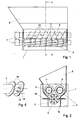
- the apparatus shown in the Figures comprises a rectangular housing 1 in which three mutually parallel rollers 3, 4 and 5 are arranged between funnel-shaped inner walls 2.
- a feed-in funnel 6 Provided at the top side of the housing 1 is a feed-in funnel 6.
- a feed-out funnel formed by the lower portion of the inner walls 2, whereby the reduced and crushed material can be dumped onto a discharge conveying belt (not shown).
- rollers 3, 4 and 5 are driven by means of hydromotors 7 controlled from a hydraulic unit (not shown) disposed elsewhere.
- This unit is built up from an electromotor mounting a pump distribution box having four hydraulic pumps, each pump incorporated into a closed system; one pump for each of the upper rollers 3 and 4 and two pumps which jointly provide the drive of the lower roller 5.
- a control box (not shown) having a computer, monitor and keyboard (PLC - "programmable logic control" with display) is installed.
- PLC "programmable logic control" with display
- the main process data can be displayed.
- the apparatus can be controlled via the keyboard and operates fully automatically. However, the possibility for a manual operation remains present. If necessary, the process parameters can be modified via the keyboard.
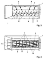
- the (first) roller 3 is provided with ribs formed by two screw threads 8 and 9 having opposite leads for conveying material that is fed substantially centrally above the rollers laterally outwards in both directions.
- the (second) roller 4 is provided with ribs formed by oval disks 10 which are obliquely provided around the roller 4 and which, when the roller 4 is driven, perform a reciprocating movement, viewed in axial direction.
- the oval disks 10 are arranged at such an angle and are of such eccentricity that the enveloping line is formed by a cylinder having a circular, straight section.
- the angle ⁇ at which the oval disks 10 are arranged is approximately equal to the angle which the tangent to the screw threads on the roller 3 makes relative to a straight section.
- cutting elements 11 are provided between the oval disks, which cutting elements are tangentially staggered in the longitudinal direction of the roller.
- the oval disks 10, as indicated in Fig. 5, over a part of their circumference have a curvature 12 which deviates such that a cutting face 13 directed to the center of the disks is formed. These cutting faces 13 are staggered for the successive oval disks 10.
- the third roller 5 has round disks 14 provided straight around it and partitions 15 arranged between these disks in a slightly spiral configuration.
- a blade 16 Provided next to this roller 5, on either side thereof, is a blade 16 for further reducing and crushing material projecting from the sections 17 formed by the round disks 14 and the partitions 15.
- the operation of the apparatus is as follows.
- the material to be reduced and crushed is supplied via the feed-in funnel 6 and passed down between the rollers 3 and 4, which normally rotate towards each other in the feeding direction, the material being cut along the top edge of the ribs due to the difference in axial speed of the ribs 8, 9 and 10 on the rollers 3 and 4, which cutting action is reinforced by the cutting elements 11 on the roller 4 and the cutting faces 13 on the oval disks 10.
- a shearing action is created between the screw thread and the oval disks.
- this relative speed decreases, a clearing movement is created. During this clearing movement, the cutting faces 13 and the cutting elements 11 pass the screw thread, so that an additional reduction takes place.
- the speed of the rollers 3 and 4 can be adjusted back. By measuring the load permanently, this back-adjustment can be realized automatically. If the load exceeds a predetermined value, the direction of rotation of the rollers 3 and 4 is reversed. This may of course also be effected automatically.
- the invention is by no means limited to the embodiment described herein with reference to the Figures, but comprises all kinds of modifications hereto in so far as they fall within the scope of the following claims.
- the third roller need not necessarily be present.
- cutting elements if necessary tangentially staggered, may also be provided on the first roller.
- the cutting elements mounted on the top roller or rollers may be detachable, enabling them to be readily replaced when they break down.
Landscapes
- Engineering & Computer Science (AREA)
- Food Science & Technology (AREA)
- Disintegrating Or Milling (AREA)
- Crushing And Grinding (AREA)
- Crushing And Pulverization Processes (AREA)
Applications Claiming Priority (2)
| Application Number | Priority Date | Filing Date | Title |
|---|---|---|---|
| NL1007069 | 1997-09-18 | ||
| NL1007069A NL1007069C2 (nl) | 1997-09-18 | 1997-09-18 | Inrichting voor het verkleinen en vermalen van grof materiaal. |
Publications (2)
| Publication Number | Publication Date |
|---|---|
| EP0903183A1 true EP0903183A1 (fr) | 1999-03-24 |
| EP0903183B1 EP0903183B1 (fr) | 2002-12-11 |
Family
ID=19765700
Family Applications (1)
| Application Number | Title | Priority Date | Filing Date |
|---|---|---|---|
| EP98203133A Expired - Lifetime EP0903183B1 (fr) | 1997-09-18 | 1998-09-17 | Appareil de fragmentation et de concassage de gros matériaux |
Country Status (4)
| Country | Link |
|---|---|
| EP (1) | EP0903183B1 (fr) |
| AT (1) | ATE229374T1 (fr) |
| DE (1) | DE69810044T2 (fr) |
| NL (1) | NL1007069C2 (fr) |
Cited By (6)
| Publication number | Priority date | Publication date | Assignee | Title |
|---|---|---|---|---|
| WO2008117096A3 (fr) * | 2007-03-28 | 2008-12-11 | Foevarosi Csatornazasi Muevek | Procédé et appareil destinés à traiter des déchets contenant des substances organiques |
| EP2233644A1 (fr) * | 2009-03-24 | 2010-09-29 | Allu Finland Oy | Godet avec broyeur |
| FR3043091A1 (fr) * | 2015-11-04 | 2017-05-05 | Haffner Energy | Dispositif de thermolyse avec mecanisme de fragmentation |
| CN109092537A (zh) * | 2018-08-06 | 2018-12-28 | 文福友 | 一种高效垃圾粉碎装置 |
| CN110577043A (zh) * | 2019-08-19 | 2019-12-17 | 长沙市天珍科技有限公司 | 一种专用园林绿化垃圾回收处理装置 |
| EP3705183A1 (fr) * | 2019-03-04 | 2020-09-09 | Briklis, spol. s.r.o. | Broyeur de concassage et broyage de matériaux |
Families Citing this family (2)
| Publication number | Priority date | Publication date | Assignee | Title |
|---|---|---|---|---|
| DE102012216914B4 (de) | 2012-09-20 | 2017-01-05 | Hammel GmbH & Co.KG | Zerkleinerungsvorrichtung |
| CN108043544A (zh) * | 2017-12-13 | 2018-05-18 | 安徽金龙山葛业有限公司 | 一种野葛根汁的分离设备 |
Citations (6)
| Publication number | Priority date | Publication date | Assignee | Title |
|---|---|---|---|---|
| EP0081539A1 (fr) | 1981-06-12 | 1983-06-22 | Harry Wilhelm Wexell | Procede et dipositif de desintegration de gros materiaux. |
| EP0291227A2 (fr) * | 1987-05-09 | 1988-11-17 | Kyokuto Kaihatsu Kogyo Co., Ltd. | Appareil de broyage |
| JPH0248048A (ja) * | 1988-08-10 | 1990-02-16 | Kyokuto Kaihatsu Kogyo Co Ltd | ディスク形破砕機 |
| US5248100A (en) * | 1991-07-22 | 1993-09-28 | Kurimoto, Ltd. | Crusher with rotor for shearing |
| JPH07847A (ja) * | 1993-06-18 | 1995-01-06 | Nippon Spindle Mfg Co Ltd | 粗大物破砕装置 |
| WO1995030485A1 (fr) * | 1994-05-06 | 1995-11-16 | Iggesund Shredders Ab | Dispositif de desintegration |
-
1997
- 1997-09-18 NL NL1007069A patent/NL1007069C2/nl not_active IP Right Cessation
-
1998
- 1998-09-17 DE DE69810044T patent/DE69810044T2/de not_active Expired - Fee Related
- 1998-09-17 EP EP98203133A patent/EP0903183B1/fr not_active Expired - Lifetime
- 1998-09-17 AT AT98203133T patent/ATE229374T1/de not_active IP Right Cessation
Patent Citations (6)
| Publication number | Priority date | Publication date | Assignee | Title |
|---|---|---|---|---|
| EP0081539A1 (fr) | 1981-06-12 | 1983-06-22 | Harry Wilhelm Wexell | Procede et dipositif de desintegration de gros materiaux. |
| EP0291227A2 (fr) * | 1987-05-09 | 1988-11-17 | Kyokuto Kaihatsu Kogyo Co., Ltd. | Appareil de broyage |
| JPH0248048A (ja) * | 1988-08-10 | 1990-02-16 | Kyokuto Kaihatsu Kogyo Co Ltd | ディスク形破砕機 |
| US5248100A (en) * | 1991-07-22 | 1993-09-28 | Kurimoto, Ltd. | Crusher with rotor for shearing |
| JPH07847A (ja) * | 1993-06-18 | 1995-01-06 | Nippon Spindle Mfg Co Ltd | 粗大物破砕装置 |
| WO1995030485A1 (fr) * | 1994-05-06 | 1995-11-16 | Iggesund Shredders Ab | Dispositif de desintegration |
Non-Patent Citations (2)
| Title |
|---|
| PATENT ABSTRACTS OF JAPAN vol. 014, no. 211 (C - 0715) 2 May 1990 (1990-05-02) * |
| PATENT ABSTRACTS OF JAPAN vol. 095, no. 004 31 May 1995 (1995-05-31) * |
Cited By (9)
| Publication number | Priority date | Publication date | Assignee | Title |
|---|---|---|---|---|
| WO2008117096A3 (fr) * | 2007-03-28 | 2008-12-11 | Foevarosi Csatornazasi Muevek | Procédé et appareil destinés à traiter des déchets contenant des substances organiques |
| AU2008231604B2 (en) * | 2007-03-28 | 2010-12-16 | Veolia Bioenergy Europe Kft. | Method and apparatus for processing biomass waste |
| US8100354B2 (en) | 2007-03-28 | 2012-01-24 | Veolia Bioenergy Europe Kft. | Apparatus for processing utility waste with biodegradable organic material content |
| EA016173B1 (ru) * | 2007-03-28 | 2012-02-28 | Веолиа Байоэнерджи Юроп Кфт. | Устройство для переработки утилизируемых отходов, содержащих органические вещества |
| EP2233644A1 (fr) * | 2009-03-24 | 2010-09-29 | Allu Finland Oy | Godet avec broyeur |
| FR3043091A1 (fr) * | 2015-11-04 | 2017-05-05 | Haffner Energy | Dispositif de thermolyse avec mecanisme de fragmentation |
| CN109092537A (zh) * | 2018-08-06 | 2018-12-28 | 文福友 | 一种高效垃圾粉碎装置 |
| EP3705183A1 (fr) * | 2019-03-04 | 2020-09-09 | Briklis, spol. s.r.o. | Broyeur de concassage et broyage de matériaux |
| CN110577043A (zh) * | 2019-08-19 | 2019-12-17 | 长沙市天珍科技有限公司 | 一种专用园林绿化垃圾回收处理装置 |
Also Published As
| Publication number | Publication date |
|---|---|
| EP0903183B1 (fr) | 2002-12-11 |
| ATE229374T1 (de) | 2002-12-15 |
| NL1007069C2 (nl) | 1999-03-22 |
| DE69810044T2 (de) | 2003-09-25 |
| DE69810044D1 (de) | 2003-01-23 |
Similar Documents
| Publication | Publication Date | Title |
|---|---|---|
| US4134556A (en) | Tire shredder | |
| EP1068904B1 (fr) | Installation pour la granulation d'une matière plastique | |
| EP0338002B1 (fr) | Appareil de desintegration de materiaux tels que des dechets | |
| EP0394030B1 (fr) | Broyeur à vis | |
| EP0903183B1 (fr) | Appareil de fragmentation et de concassage de gros matériaux | |
| WO2008068639A2 (fr) | Dispositifs de régulation de matériau et systèmes de distribution de matériau ayant ces dispositifs | |
| US5566895A (en) | Device for cutting meat | |
| US4720047A (en) | Auger for conveying materials such as manure | |
| US4566640A (en) | Separating machine having overlapping screw pump | |
| GB2217232A (en) | Helical roll crusher | |
| US4917310A (en) | Processing apparatus for solid refuse | |
| EP0521081B1 (fr) | Appareil a reduire les materiaux | |
| US5320293A (en) | Rotary grinder exploying blades | |
| US4874024A (en) | Wood processing device having self-reversing feature | |
| US4489896A (en) | Processing apparatus for solid urban refuse and plastic bags filled with same | |
| GB2267235A (en) | Screening apparatus | |
| US4142689A (en) | Shredder-feed device | |
| US4802631A (en) | Winged cutting knife for producing wood chips or flakes | |
| DE19924826A1 (de) | Vorrichtung zum Zerkleinern von zähelastischem Zerkleinerungsgut | |
| EP0405313B1 (fr) | Dispositif de désileusement et de transport | |
| GB2085741A (en) | A machine for the treatment of wet particulate materials | |
| CN2137982Y (zh) | 剪切式滤饼破碎机 | |
| US6273350B1 (en) | Material handling apparatus | |
| JPS63256149A (ja) | 粗大物破砕装置 | |
| US4520963A (en) | Process and equipment for continuous cutting of material |
Legal Events
| Date | Code | Title | Description |
|---|---|---|---|
| PUAI | Public reference made under article 153(3) epc to a published international application that has entered the european phase |
Free format text: ORIGINAL CODE: 0009012 |
|
| AK | Designated contracting states |
Kind code of ref document: A1 Designated state(s): AT BE CH DE IT LI |
|
| AX | Request for extension of the european patent |
Free format text: AL;LT;LV;MK;RO;SI |
|
| 17P | Request for examination filed |
Effective date: 19990924 |
|
| AKX | Designation fees paid |
Free format text: AT BE CH DE IT LI |
|
| 17Q | First examination report despatched |
Effective date: 20011001 |
|
| GRAG | Despatch of communication of intention to grant |
Free format text: ORIGINAL CODE: EPIDOS AGRA |
|
| GRAG | Despatch of communication of intention to grant |
Free format text: ORIGINAL CODE: EPIDOS AGRA |
|
| GRAH | Despatch of communication of intention to grant a patent |
Free format text: ORIGINAL CODE: EPIDOS IGRA |
|
| GRAH | Despatch of communication of intention to grant a patent |
Free format text: ORIGINAL CODE: EPIDOS IGRA |
|
| GRAA | (expected) grant |
Free format text: ORIGINAL CODE: 0009210 |
|
| AK | Designated contracting states |
Kind code of ref document: B1 Designated state(s): AT BE CH DE IT LI |
|
| REF | Corresponds to: |
Ref document number: 229374 Country of ref document: AT Date of ref document: 20021215 Kind code of ref document: T |
|
| REG | Reference to a national code |
Ref country code: CH Ref legal event code: EP |
|
| REF | Corresponds to: |
Ref document number: 69810044 Country of ref document: DE Date of ref document: 20030123 |
|
| REG | Reference to a national code |
Ref country code: CH Ref legal event code: NV Representative=s name: SCHMAUDER & PARTNER AG PATENTANWALTSBUERO |
|
| PGFP | Annual fee paid to national office [announced via postgrant information from national office to epo] |
Ref country code: BE Payment date: 20030819 Year of fee payment: 6 |
|
| PGFP | Annual fee paid to national office [announced via postgrant information from national office to epo] |
Ref country code: AT Payment date: 20030910 Year of fee payment: 6 |
|
| PGFP | Annual fee paid to national office [announced via postgrant information from national office to epo] |
Ref country code: CH Payment date: 20030923 Year of fee payment: 6 |
|
| PLBE | No opposition filed within time limit |
Free format text: ORIGINAL CODE: 0009261 |
|
| STAA | Information on the status of an ep patent application or granted ep patent |
Free format text: STATUS: NO OPPOSITION FILED WITHIN TIME LIMIT |
|
| PGFP | Annual fee paid to national office [announced via postgrant information from national office to epo] |
Ref country code: DE Payment date: 20031126 Year of fee payment: 6 |
|
| 26N | No opposition filed |
Effective date: 20030912 |
|
| PG25 | Lapsed in a contracting state [announced via postgrant information from national office to epo] |
Ref country code: AT Free format text: LAPSE BECAUSE OF NON-PAYMENT OF DUE FEES Effective date: 20040917 |
|
| PG25 | Lapsed in a contracting state [announced via postgrant information from national office to epo] |
Ref country code: LI Free format text: LAPSE BECAUSE OF NON-PAYMENT OF DUE FEES Effective date: 20040930 Ref country code: CH Free format text: LAPSE BECAUSE OF NON-PAYMENT OF DUE FEES Effective date: 20040930 Ref country code: BE Free format text: LAPSE BECAUSE OF NON-PAYMENT OF DUE FEES Effective date: 20040930 |
|
| BERE | Be: lapsed |
Owner name: *VISNO MACHINEFABRIEK B.V. Effective date: 20040930 |
|
| PG25 | Lapsed in a contracting state [announced via postgrant information from national office to epo] |
Ref country code: DE Free format text: LAPSE BECAUSE OF NON-PAYMENT OF DUE FEES Effective date: 20050401 |
|
| REG | Reference to a national code |
Ref country code: CH Ref legal event code: PL |
|
| PG25 | Lapsed in a contracting state [announced via postgrant information from national office to epo] |
Ref country code: IT Free format text: LAPSE BECAUSE OF NON-PAYMENT OF DUE FEES Effective date: 20050917 |
|
| BERE | Be: lapsed |
Owner name: *VISNO MACHINEFABRIEK B.V. Effective date: 20040930 |