EP0903517A2 - Steuereinrichtung für Überbrückungskupplung - Google Patents
Steuereinrichtung für Überbrückungskupplung Download PDFInfo
- Publication number
- EP0903517A2 EP0903517A2 EP98117497A EP98117497A EP0903517A2 EP 0903517 A2 EP0903517 A2 EP 0903517A2 EP 98117497 A EP98117497 A EP 98117497A EP 98117497 A EP98117497 A EP 98117497A EP 0903517 A2 EP0903517 A2 EP 0903517A2
- Authority
- EP
- European Patent Office
- Prior art keywords
- lock
- torque
- engine torque
- input shaft
- clutch
- Prior art date
- Legal status (The legal status is an assumption and is not a legal conclusion. Google has not performed a legal analysis and makes no representation as to the accuracy of the status listed.)
- Granted
Links
- 230000005540 biological transmission Effects 0.000 claims abstract description 14
- 230000007423 decrease Effects 0.000 description 3
- 239000000446 fuel Substances 0.000 description 3
- 238000010276 construction Methods 0.000 description 2
- 230000003247 decreasing effect Effects 0.000 description 2
- 230000003111 delayed effect Effects 0.000 description 1
- 238000010586 diagram Methods 0.000 description 1
- 239000012530 fluid Substances 0.000 description 1
- 230000004048 modification Effects 0.000 description 1
- 238000012986 modification Methods 0.000 description 1
Images


Classifications
-
- F—MECHANICAL ENGINEERING; LIGHTING; HEATING; WEAPONS; BLASTING
- F16—ENGINEERING ELEMENTS AND UNITS; GENERAL MEASURES FOR PRODUCING AND MAINTAINING EFFECTIVE FUNCTIONING OF MACHINES OR INSTALLATIONS; THERMAL INSULATION IN GENERAL
- F16H—GEARING
- F16H61/00—Control functions within control units of change-speed- or reversing-gearings for conveying rotary motion ; Control of exclusively fluid gearing, friction gearing, gearings with endless flexible members or other particular types of gearing
- F16H61/14—Control of torque converter lock-up clutches
-
- B—PERFORMING OPERATIONS; TRANSPORTING
- B60—VEHICLES IN GENERAL
- B60W—CONJOINT CONTROL OF VEHICLE SUB-UNITS OF DIFFERENT TYPE OR DIFFERENT FUNCTION; CONTROL SYSTEMS SPECIALLY ADAPTED FOR HYBRID VEHICLES; ROAD VEHICLE DRIVE CONTROL SYSTEMS FOR PURPOSES NOT RELATED TO THE CONTROL OF A PARTICULAR SUB-UNIT
- B60W2510/00—Input parameters relating to a particular sub-units
- B60W2510/06—Combustion engines, Gas turbines
- B60W2510/0657—Engine torque
-
- B—PERFORMING OPERATIONS; TRANSPORTING
- B60—VEHICLES IN GENERAL
- B60W—CONJOINT CONTROL OF VEHICLE SUB-UNITS OF DIFFERENT TYPE OR DIFFERENT FUNCTION; CONTROL SYSTEMS SPECIALLY ADAPTED FOR HYBRID VEHICLES; ROAD VEHICLE DRIVE CONTROL SYSTEMS FOR PURPOSES NOT RELATED TO THE CONTROL OF A PARTICULAR SUB-UNIT
- B60W2510/00—Input parameters relating to a particular sub-units
- B60W2510/10—Change speed gearings
- B60W2510/1025—Input torque
-
- B—PERFORMING OPERATIONS; TRANSPORTING
- B60—VEHICLES IN GENERAL
- B60W—CONJOINT CONTROL OF VEHICLE SUB-UNITS OF DIFFERENT TYPE OR DIFFERENT FUNCTION; CONTROL SYSTEMS SPECIALLY ADAPTED FOR HYBRID VEHICLES; ROAD VEHICLE DRIVE CONTROL SYSTEMS FOR PURPOSES NOT RELATED TO THE CONTROL OF A PARTICULAR SUB-UNIT
- B60W2540/00—Input parameters relating to occupants
- B60W2540/10—Accelerator pedal position
- B60W2540/106—Rate of change
-
- F—MECHANICAL ENGINEERING; LIGHTING; HEATING; WEAPONS; BLASTING
- F16—ENGINEERING ELEMENTS AND UNITS; GENERAL MEASURES FOR PRODUCING AND MAINTAINING EFFECTIVE FUNCTIONING OF MACHINES OR INSTALLATIONS; THERMAL INSULATION IN GENERAL
- F16H—GEARING
- F16H61/00—Control functions within control units of change-speed- or reversing-gearings for conveying rotary motion ; Control of exclusively fluid gearing, friction gearing, gearings with endless flexible members or other particular types of gearing
- F16H61/14—Control of torque converter lock-up clutches
- F16H61/143—Control of torque converter lock-up clutches using electric control means
- F16H2061/145—Control of torque converter lock-up clutches using electric control means for controlling slip, e.g. approaching target slip value
-
- F—MECHANICAL ENGINEERING; LIGHTING; HEATING; WEAPONS; BLASTING
- F16—ENGINEERING ELEMENTS AND UNITS; GENERAL MEASURES FOR PRODUCING AND MAINTAINING EFFECTIVE FUNCTIONING OF MACHINES OR INSTALLATIONS; THERMAL INSULATION IN GENERAL
- F16H—GEARING
- F16H59/00—Control inputs to control units of change-speed- or reversing-gearings for conveying rotary motion
- F16H59/14—Inputs being a function of torque or torque demand
- F16H59/141—Inputs being a function of torque or torque demand of rate of change of torque or torque demand
Definitions
- This invention relates to lock-up control devices that control engaging forces of lock-up clutches, which share engine outputs with torque converters to transmit them toward input shafts of automatic transmissions of cars.
- the paper of Japanese Patent Application, Publication No. Hei 7-332479 discloses an example of the lock-up control device that controls engaging force of the lock-up clutch, which shares engine output with the torque converter to transmit it toward the input shaft of the automatic transmission of the car, wherein the engine output is controlled in response to throttle opening.
- This type of the lock-up control device has an input shaft torque estimation unit, which estimates input shaft torque of the transmission, in other words, turbine torque of the torque converter. So, the device controls the engaging force of the lock-up clutch based on the input shaft torque estimated by the input shaft torque estimation unit.
- the above lock-up control device has a merit that the aforementioned input shaft torque can be calculated with a high precision.
- the rise timing of the input shaft torque should be delayed from the rise timing of the real engine torque.
- the aforementioned lock-up control device that controls the engaging force of the lock-up clutch on the basis of the input shaft torque suffers from a problem that a delay occurs in control of the lock-up clutch in the case where the real engine torque sharply and suddenly increases. In consideration of the dynamics of the lock-up clutch itself, such a control delay will be increased further more.
- chip-in phenomenon According to which the engine speed decreases because the engaging force of the lock-up clutch increases after the engine speed increases unnecessarily high. In other words, in the chip-in phenomenon, the engine speed increases unnecessarily high, then, the engine speed decreases.
- This chip-in phenomenon is disadvantageous for the car (and driver) in aspects of drivability and fuel efficiency.
- a lock-up control device is provided to control engaging force of a lock-up clutch, which shares engine output with a torque converter to transmit it toward an input shaft of a transmission.
- input shaft torque is estimated based on engine speed and engine intake negative pressure, while engine torque is estimated based on engine speed and throttle opening.
- a weight coefficient is produced based on an amount of variations of the engine torque when the amount of variations is greater than a prescribed value.
- weighted mean engine torque is calculated by the input shaft torque and engine torque in accordance with the weight coefficient.
- the lock-up clutch is controlled based on the weighted mean engine torque in such a way that the engaging force of the lock-up clutch is increased in response to the rise timing of the weighted mean engine torque.
- the weight coefficient is determined in such a way that the engine torque is given high distributed weight in the weighted mean engine torque as compared with the input shaft torque.
- the input shaft torque is given high distributed weight in the weighted mean engine torque as compared with the engine torque.
- the engaging force of the lock-up clutch substantially in response to the input shaft torque which is estimated with a high precision.
- FIG. 1 shows an example of mechanical construction with regard to the lock-up clutch, torque converter and transmission of the car.
- a cover 11 is connected to a crank shaft, which corresponds to an output shaft of an engine (not shown).
- a pump impeller 12 is fixed to the cover 11 and is rotated together with the cover 11 by driving force of the engine.
- a turbine runner 13 is arranged at an opposite side of the pump impeller 12.
- An input shaft 14 of a transmission (not shown) is fixed to the turbine runner 13.
- a stator 15 is arranged at interior portions of the pump impeller 12 and the turbine runner 13. Incidentally, the pump impeller 12, turbine runner 13 and stator 15 are assembled together to construct a torque converter 16.
- a lock-up clutch 18 shares engine output with the torque converter 16 to transmit it toward the input shaft 14 of the transmission.
- the lockup clutch 18 is arranged between the cover 11 and turbine runner 13 and is also fixed to the input shaft 14 of the transmission. In response to hydraulic pressure difference detected between the cover 11 and the turbine runner 13, the lock-up clutch 18 comes in contact with or leaves from the cover 11.
- FIG. 2 shows a configuration of a lock-up control device 20 in accordance with the preferred embodiment of the invention.
- the lock-up control device 20 of FIG. 2 controls the aforementioned hydraulic pressure difference so as to control engaging force of the lock-up clutch 18 against the cover 11.
- the lock-up control device 20 is configured by an input shaft torque estimation unit 21, an engine torque estimation unit 22, a weighted mean calculation unit 23 and a control unit 24.
- the input shaft torque estimation unit 21 produces torque TT of the input shaft 14 of the transmission as an estimated value. Based on real load that is defined by prescribed elements such as engine speed NE and engine intake negative pressure Pb, the input shaft torque estimation unit 21 produces the input shaft torque TT in accordance with a map whose content is set in advance. Other than the aforementioned elements defining the real load, it is possible to employ a slip state of the torque converter 16, in other words, a relationship between revolutions of the engine and revolutions of the input shaft 14.
- the engine torque estimation unit 22 Based on predicted load that is defined by the engine speed Ne as well as throttle opening TH for controlling engine output, the engine torque estimation unit 22 produces engine torque TETH as an estimated value in accordance with a map whose content is set in advance.
- the engine is controlled by a throttle valve control device (not shown), which electrically controls real throttle opening in such a way that the throttle opening TH is obtained.
- the throttle opening TH is produced in accordance with a preset map on the basis of various kinds of car travel conditions as well as accel pedal opening which is detected. Then, the throttle opening TH produced by the throttle valve control device is input to the engine torque estimation unit 22.
- the weighted mean calculation unit 23 calculates an amount of variations "DTETH" of the engine torque, which is produced by the engine torque estimation unit 22. If the amount of variations DTETH is greater than a prescribed value DTETH1, the weighted mean calculation unit 22 produces a weight coefficient RLC based on DTETH. This weight coefficient RLC is retrieved from a table whose content indicates a characteristic curve shown in FIG. 3.
- the weight coefficient RLC read from the table is changed in four stages, which are respectively defined using prescribed values DTETH1, DTETH2 and DTETH3.
- the weight coefficient RCL is set at zero.
- the weight coefficient RLC increases from zero in proportional to an increase of the amount of variations DTETH.
- the weight coefficient RCL increases up to "1" in proportional to an increase of the amount of variations DTETH.
- a proportional constant used in the range between DTETH2 and DTETH3 is smaller than a proportional constant used in the aforementioned range between DTETH1 and DTETH2.
- the weight coefficient RCL is set at "1".
- the control unit 24 controls engaging force of the lock-up clutch 18 based on the weighted mean value of torque TTLC calculated by the weighted mean calculation unit 23.
- the control unit 24 controls the lock-up clutch 18 in such a way that the engaging force is increased in response to the rise timing of the weighted mean value of torque TTLC.
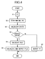
- step S1 the input shaft torque estimation unit 21 performs estimation based on the read load defined by the engine speed Ne and engine intake negative pressure Pb to produce input shaft torque TT in accordance with the preset map.
- step S2 the engine torque estimation unit 22 performs estimation based on the predicted load defined by the engine speed Ne and throttle opening TH to produce engine torque TETH in accordance with the preset map
- step S3 the weighted mean calculation unit 23 calculates an amount of variations DTETH based on the engine torque TETH produced by the engine torque estimation unit 22.
- step S4 a decision is made as to whether the amount of variations DTETH is greater than the prescribed value DTETH1 or not. If the amount of variations DTETH is greater than the prescribed value DTETH1, the lock-up control device 20 transfers control to step S5, wherein a weight coefficient RLC is produced based on DTETH with reference to the aforementioned table whose content is shown in FIG. 3.
- step S6 the weighted mean calculation unit 23 performs weighted mean calculation using the weight coefficient RLC to produce a weighted mean value TTLC for the input shaft torque TT and the engine torque TETH. If the lock-up control device 20 makes a decision in step S4 that the amount of variations DTETH is less than the prescribed value DTETH1, it outputs the input shaft torque TT, which is produced in the foregoing step S1, in step S7.
- the weighted mean calculation unit 23 outputs either the weighted mean value TTLC or the input shaft torque TT.
- the control unit 24 controls engaging force of the lock-up clutch 18 based on one of the weighted mean value TTLC and input shaft torque TT, which is output from the weighted mean calculation unit 23.
- FIG. 5 shows an example of relationships between the throttle opening TH, amount of variations DTETH, weight coefficient RLC and torque TRQ, which are varied in a lapse of time in response to the control of the lock-up control device 20.
- FIG. 5 shows the example that the throttle opening TH increases (or rises) sharply.
- the amount of variations DTETH is increased, while the weight coefficient RLC is increased to "1".
- the torque TRQ is varied in such a way that the weighted mean value TTLC coincides with the engine torque TETH.
- the amount of variations DTETH is decreased, while the weight coefficient RLC is decreased as well.
- the torque TRQ is varied in such a way that the weighted mean value TTLC gradually coincides with the input shaft torque TT as compared with the engine torque TETH, in other words, the input shaft torque TT is given (relatively) high distributed weight as compared with the engine torque TETH with respect to the weighted mean value TTLC. After completion of the rise time of the throttle opening TH, the torque TRQ will completely coincide with the input shaft torque TT.
- the engine torque estimation unit 22 Due to the aforementioned control, under a sudden change state where the real engine torque rises sharply and suddenly, the engine torque estimation unit 22 produces the amount of variations DTETH for the engine torque, which becomes large. So, by detecting an event that DTETH becomes large, distributed weight of the engine torque TETH, which is produced by the weighted mean calculation unit 23 based on the engine speed Ne and throttle opening TH, is made large in the weighted mean value TTLC. Information of the engine speed Ne and throttle opening TH can be obtained at a very early stage in the change event of the real engine torque. So, the engine torque TETH which is produced based on the above information rises earlier than the input shaft torque TT which is produced by the input shaft torque estimation unit 21.
- the lock-up control device 20 controls the engaging force of the lock-up clutch 18 based on the weighted mean value TTLC in which the engine torque TETH is given high distributed weight. So, it is possible to increase the engaging force of the lock-up clutch 18 promptly in response to the rise mode of the real engine torque. Thus, it is possible to avoid occurrence of control delay in controlling of the lock-up clutch 18.
- the lock-up control device of the present embodiment is capable of avoiding occurrence of the chip-in phenomenon, so that it is possible to improve the drivability as well as the fuel efficiency.
- the present embodiment is capable of controlling the engaging force of the lock-up clutch 18 in response to the input shaft torque TT whose precision is relatively high or in response to the weighted mean value TTLC in which the input shaft torque TT is given high distributed weight.
- the weighted mean value TTLC is configured using the input shaft torque TT produced by the input shaft torque estimation unit 21 and the engine torque TETH produced by the engine torque estimation unit 22, which are given distributed weights respectively.
- the present embodiment is capable of controlling the lock-up clutch 18 without damaging high precision and without being influenced by the control delay.
- the present embodiment is designed as follows:
- the weighted mean value TTLC configured by the input shaft torque TT and engine torque TETH is calculated based on the weight coefficient RLC which is produced based on the amount of variations DTETH.
- the weighted mean value TTLC configured by the input shaft torque TT and engine torque TETH is calculated based on the weight coefficient RLC which is produced based on the amount of variations DTH.
- a lock-up control device is provided to control engaging force of a lock-up clutch, which shares engine output with a torque converter to transmit it toward an input shaft of a transmission.
- input shaft torque is estimated based on engine speed and engine intake negative pressure
- engine torque is estimated based on engine speed and throttle opening.
- a weight coefficient is produced based on an amount of variations of the engine torque when the amount of variations is greater than a prescribed value.
- weighted mean engine torque is calculated by the input shaft torque and engine torque in accordance with the weight coefficient.
- the lock-up control device controls the lock-up clutch based on the weighted mean engine torque in such a way that the engaging force of the lock-up clutch is increased in response to the rise timing of the weighted mean engine torque.
- the weight coefficient is determined in such a way that the engine torque is given high distributed weight in the weighted mean engine torque as compared with the input shaft torque.
Landscapes
- Engineering & Computer Science (AREA)
- General Engineering & Computer Science (AREA)
- Mechanical Engineering (AREA)
- Control Of Fluid Gearings (AREA)
Applications Claiming Priority (3)
| Application Number | Priority Date | Filing Date | Title |
|---|---|---|---|
| JP252533/97 | 1997-09-17 | ||
| JP25253397 | 1997-09-17 | ||
| JP25253397A JP3703952B2 (ja) | 1997-09-17 | 1997-09-17 | ロックアップクラッチ制御装置 |
Publications (3)
| Publication Number | Publication Date |
|---|---|
| EP0903517A2 true EP0903517A2 (de) | 1999-03-24 |
| EP0903517A3 EP0903517A3 (de) | 1999-10-13 |
| EP0903517B1 EP0903517B1 (de) | 2003-06-04 |
Family
ID=17238703
Family Applications (1)
| Application Number | Title | Priority Date | Filing Date |
|---|---|---|---|
| EP98117497A Expired - Lifetime EP0903517B1 (de) | 1997-09-17 | 1998-09-15 | Steuereinrichtung für Überbrückungskupplung |
Country Status (5)
| Country | Link |
|---|---|
| US (1) | US6009988A (de) |
| EP (1) | EP0903517B1 (de) |
| JP (1) | JP3703952B2 (de) |
| CA (1) | CA2247168C (de) |
| DE (1) | DE69815239T2 (de) |
Cited By (4)
| Publication number | Priority date | Publication date | Assignee | Title |
|---|---|---|---|---|
| EP1403566A3 (de) * | 2002-09-30 | 2006-10-04 | JATCO Ltd | Methode und Vorrichtung zur Hydraulikdrucksteuerung eines automatischen Getriebes mit einem Überbrückungsventil |
| EP1531288A3 (de) * | 2003-11-12 | 2008-02-13 | Nissan Motor Co., Ltd. | Kraftantriebsvorrichtung mit einem Drehmomentwandler mit einer Überbrückungskupplung und Überbrückungssteuerungverfahren |
| EP1739329A3 (de) * | 2005-06-29 | 2009-11-11 | Nissan Motor Co., Ltd. | Vorrichtung und Verfahren zur Steuerung der Betätigungskraft einer Überbrückungskupplung |
| CN106662244A (zh) * | 2014-07-09 | 2017-05-10 | 加特可株式会社 | 锁止离合器的控制装置 |
Families Citing this family (1)
| Publication number | Priority date | Publication date | Assignee | Title |
|---|---|---|---|---|
| JP2004108300A (ja) * | 2002-09-19 | 2004-04-08 | Jatco Ltd | エンジントルク推定装置およびエンジントルク推定方法 |
Citations (1)
| Publication number | Priority date | Publication date | Assignee | Title |
|---|---|---|---|---|
| JPH07332479A (ja) | 1994-06-06 | 1995-12-22 | Hitachi Ltd | トルク補正装置 |
Family Cites Families (3)
| Publication number | Priority date | Publication date | Assignee | Title |
|---|---|---|---|---|
| KR960001444A (ko) * | 1994-06-06 | 1996-01-25 | 가나이 쯔도무 | 파워트레인의 제어장치 및 제어방법 |
| JP3567491B2 (ja) * | 1994-07-26 | 2004-09-22 | 株式会社デンソー | ロックアップクラッチのスリップ制御装置 |
| US5527238A (en) * | 1995-04-10 | 1996-06-18 | Ford Motor Company | Automatic transmission bypass clutch slip control using nonlinear nverse dynamics |
-
1997
- 1997-09-17 JP JP25253397A patent/JP3703952B2/ja not_active Expired - Fee Related
-
1998
- 1998-09-15 CA CA002247168A patent/CA2247168C/en not_active Expired - Fee Related
- 1998-09-15 US US09/153,302 patent/US6009988A/en not_active Expired - Fee Related
- 1998-09-15 EP EP98117497A patent/EP0903517B1/de not_active Expired - Lifetime
- 1998-09-15 DE DE69815239T patent/DE69815239T2/de not_active Expired - Fee Related
Patent Citations (1)
| Publication number | Priority date | Publication date | Assignee | Title |
|---|---|---|---|---|
| JPH07332479A (ja) | 1994-06-06 | 1995-12-22 | Hitachi Ltd | トルク補正装置 |
Cited By (8)
| Publication number | Priority date | Publication date | Assignee | Title |
|---|---|---|---|---|
| EP1403566A3 (de) * | 2002-09-30 | 2006-10-04 | JATCO Ltd | Methode und Vorrichtung zur Hydraulikdrucksteuerung eines automatischen Getriebes mit einem Überbrückungsventil |
| EP1531288A3 (de) * | 2003-11-12 | 2008-02-13 | Nissan Motor Co., Ltd. | Kraftantriebsvorrichtung mit einem Drehmomentwandler mit einer Überbrückungskupplung und Überbrückungssteuerungverfahren |
| EP1739329A3 (de) * | 2005-06-29 | 2009-11-11 | Nissan Motor Co., Ltd. | Vorrichtung und Verfahren zur Steuerung der Betätigungskraft einer Überbrückungskupplung |
| US9020718B2 (en) | 2005-06-29 | 2015-04-28 | Nissan Motor Co., Ltd. | Engaging force control of lockup clutch |
| CN106662244A (zh) * | 2014-07-09 | 2017-05-10 | 加特可株式会社 | 锁止离合器的控制装置 |
| EP3168504A4 (de) * | 2014-07-09 | 2017-08-09 | Jatco Ltd | Sperrkupplungsteuerungsvorrichtung |
| US10125864B2 (en) | 2014-07-09 | 2018-11-13 | Jatco Ltd | Lock-up-clutch control device |
| CN106662244B (zh) * | 2014-07-09 | 2019-01-04 | 加特可株式会社 | 锁止离合器的控制装置 |
Also Published As
| Publication number | Publication date |
|---|---|
| JP3703952B2 (ja) | 2005-10-05 |
| CA2247168C (en) | 2003-03-18 |
| CA2247168A1 (en) | 1999-03-17 |
| DE69815239T2 (de) | 2004-05-06 |
| EP0903517B1 (de) | 2003-06-04 |
| JPH1194066A (ja) | 1999-04-09 |
| DE69815239D1 (de) | 2003-07-10 |
| EP0903517A3 (de) | 1999-10-13 |
| US6009988A (en) | 2000-01-04 |
Similar Documents
| Publication | Publication Date | Title |
|---|---|---|
| US7854683B2 (en) | Torque converter clutch control | |
| US8010272B2 (en) | Control device for internal combustion engine | |
| US7644812B2 (en) | Using inferred torque converter impeller speed to control an impeller clutch | |
| EP2075491B1 (de) | Sperrkupplungssteuervorrichtung für Automatikgetriebe und Steuerungsverfahren dafür | |
| CA2247174C (en) | Lock-up control device | |
| EP1605192A2 (de) | Steuerungseinrichtung für die Überbrückungskupplung eines Momentwandlers eines automatischen Getriebes | |
| JPH10122355A (ja) | ロックアップクラッチ付き自動変速機の制御装置及びその自動変速機の制御方法 | |
| US20070255472A1 (en) | Powertrain control apparatus and method | |
| JPH08296708A (ja) | 無段自動変速機の制御装置 | |
| JPH09280332A (ja) | 無段自動変速機の変速制御装置 | |
| JPH0543896B2 (de) | ||
| JP6304094B2 (ja) | ロックアップクラッチの制御装置 | |
| EP0903517B1 (de) | Steuereinrichtung für Überbrückungskupplung | |
| JP2663673B2 (ja) | ロックアップクラッチの制御装置 | |
| JP2004124966A (ja) | ベルト式無段変速機の制御装置 | |
| JP3223768B2 (ja) | 無段変速機の変速比制御装置 | |
| EP1643163B1 (de) | Vorrichtung und Verfahren zur Kompensation der Erwärmungsleistung eines stufenlosen Getriebes | |
| US11982328B2 (en) | Method for preventing stalling of an internal combustion engine of a motor vehicle | |
| JP2000145950A (ja) | トルクコンバータのスリップ制御装置 | |
| WO2020026717A1 (ja) | トルクコンバータのスリップ制御装置 | |
| AU6666200A (en) | Method of controlling upshift for an automatic transmission | |
| US7678019B2 (en) | Control device and control method for friction engagement element | |
| JP5272748B2 (ja) | 車両の駆動制御装置 | |
| JP2819587B2 (ja) | 可変容量型流体式トルクコンバータの制御方法 | |
| JP4082700B2 (ja) | トルクコンバータのスリップ制御装置 |
Legal Events
| Date | Code | Title | Description |
|---|---|---|---|
| PUAI | Public reference made under article 153(3) epc to a published international application that has entered the european phase |
Free format text: ORIGINAL CODE: 0009012 |
|
| AK | Designated contracting states |
Kind code of ref document: A2 Designated state(s): DE FR GB |
|
| AX | Request for extension of the european patent |
Free format text: AL;LT;LV;MK;RO;SI |
|
| PUAL | Search report despatched |
Free format text: ORIGINAL CODE: 0009013 |
|
| AK | Designated contracting states |
Kind code of ref document: A3 Designated state(s): AT BE CH CY DE DK ES FI FR GB GR IE IT LI LU MC NL PT SE |
|
| AX | Request for extension of the european patent |
Free format text: AL;LT;LV;MK;RO;SI |
|
| 17P | Request for examination filed |
Effective date: 19991115 |
|
| AKX | Designation fees paid |
Free format text: DE FR GB |
|
| GRAH | Despatch of communication of intention to grant a patent |
Free format text: ORIGINAL CODE: EPIDOS IGRA |
|
| GRAH | Despatch of communication of intention to grant a patent |
Free format text: ORIGINAL CODE: EPIDOS IGRA |
|
| GRAA | (expected) grant |
Free format text: ORIGINAL CODE: 0009210 |
|
| AK | Designated contracting states |
Designated state(s): DE FR GB |
|
| REG | Reference to a national code |
Ref country code: GB Ref legal event code: FG4D |
|
| REF | Corresponds to: |
Ref document number: 69815239 Country of ref document: DE Date of ref document: 20030710 Kind code of ref document: P |
|
| PGFP | Annual fee paid to national office [announced via postgrant information from national office to epo] |
Ref country code: FR Payment date: 20030925 Year of fee payment: 6 |
|
| ET | Fr: translation filed | ||
| PLBE | No opposition filed within time limit |
Free format text: ORIGINAL CODE: 0009261 |
|
| STAA | Information on the status of an ep patent application or granted ep patent |
Free format text: STATUS: NO OPPOSITION FILED WITHIN TIME LIMIT |
|
| 26N | No opposition filed |
Effective date: 20040305 |
|
| PG25 | Lapsed in a contracting state [announced via postgrant information from national office to epo] |
Ref country code: FR Free format text: LAPSE BECAUSE OF NON-PAYMENT OF DUE FEES Effective date: 20050531 |
|
| REG | Reference to a national code |
Ref country code: FR Ref legal event code: ST |
|
| PGFP | Annual fee paid to national office [announced via postgrant information from national office to epo] |
Ref country code: GB Payment date: 20080917 Year of fee payment: 11 |
|
| PGFP | Annual fee paid to national office [announced via postgrant information from national office to epo] |
Ref country code: DE Payment date: 20080926 Year of fee payment: 11 |
|
| GBPC | Gb: european patent ceased through non-payment of renewal fee |
Effective date: 20090915 |
|
| PG25 | Lapsed in a contracting state [announced via postgrant information from national office to epo] |
Ref country code: DE Free format text: LAPSE BECAUSE OF NON-PAYMENT OF DUE FEES Effective date: 20100401 |
|
| PG25 | Lapsed in a contracting state [announced via postgrant information from national office to epo] |
Ref country code: GB Free format text: LAPSE BECAUSE OF NON-PAYMENT OF DUE FEES Effective date: 20090915 |