EP0903563A1 - Dispositif pour la détection et/ou la surveillance d'un niveau prédéterminé dans un récipient - Google Patents
Dispositif pour la détection et/ou la surveillance d'un niveau prédéterminé dans un récipient Download PDFInfo
- Publication number
- EP0903563A1 EP0903563A1 EP97116486A EP97116486A EP0903563A1 EP 0903563 A1 EP0903563 A1 EP 0903563A1 EP 97116486 A EP97116486 A EP 97116486A EP 97116486 A EP97116486 A EP 97116486A EP 0903563 A1 EP0903563 A1 EP 0903563A1
- Authority
- EP
- European Patent Office
- Prior art keywords
- frequency
- elastic
- vibration
- level sensor
- membrane
- Prior art date
- Legal status (The legal status is an assumption and is not a legal conclusion. Google has not performed a legal analysis and makes no representation as to the accuracy of the status listed.)
- Granted
Links
- 238000012544 monitoring process Methods 0.000 title claims description 13
- 238000001514 detection method Methods 0.000 title description 5
- 238000011156 evaluation Methods 0.000 claims abstract description 22
- 239000012528 membrane Substances 0.000 claims description 34
- 230000005284 excitation Effects 0.000 claims description 18
- 230000005540 biological transmission Effects 0.000 claims description 9
- 239000000463 material Substances 0.000 claims description 9
- 230000010355 oscillation Effects 0.000 claims description 4
- 239000013078 crystal Substances 0.000 description 14
- 239000007788 liquid Substances 0.000 description 6
- 238000005259 measurement Methods 0.000 description 6
- 238000002604 ultrasonography Methods 0.000 description 4
- 238000013459 approach Methods 0.000 description 3
- 238000010943 off-gassing Methods 0.000 description 3
- 230000002093 peripheral effect Effects 0.000 description 3
- 238000004026 adhesive bonding Methods 0.000 description 2
- 230000037007 arousal Effects 0.000 description 2
- 238000002592 echocardiography Methods 0.000 description 2
- 238000009434 installation Methods 0.000 description 2
- 206010001497 Agitation Diseases 0.000 description 1
- 239000000853 adhesive Substances 0.000 description 1
- 230000001070 adhesive effect Effects 0.000 description 1
- 238000005452 bending Methods 0.000 description 1
- 230000015572 biosynthetic process Effects 0.000 description 1
- 238000011161 development Methods 0.000 description 1
- 230000018109 developmental process Effects 0.000 description 1
- 238000010586 diagram Methods 0.000 description 1
- 230000000694 effects Effects 0.000 description 1
- 230000007613 environmental effect Effects 0.000 description 1
- 239000002184 metal Substances 0.000 description 1
- 230000000737 periodic effect Effects 0.000 description 1
- 238000012545 processing Methods 0.000 description 1
- 238000012546 transfer Methods 0.000 description 1
- XLYOFNOQVPJJNP-UHFFFAOYSA-N water Substances O XLYOFNOQVPJJNP-UHFFFAOYSA-N 0.000 description 1
- 230000003313 weakening effect Effects 0.000 description 1
Images


Classifications
-
- G—PHYSICS
- G01—MEASURING; TESTING
- G01F—MEASURING VOLUME, VOLUME FLOW, MASS FLOW OR LIQUID LEVEL; METERING BY VOLUME
- G01F23/00—Indicating or measuring liquid level or level of fluent solid material, e.g. indicating in terms of volume or indicating by means of an alarm
- G01F23/22—Indicating or measuring liquid level or level of fluent solid material, e.g. indicating in terms of volume or indicating by means of an alarm by measuring physical variables, other than linear dimensions, pressure or weight, dependent on the level to be measured, e.g. by difference of heat transfer of steam or water
- G01F23/28—Indicating or measuring liquid level or level of fluent solid material, e.g. indicating in terms of volume or indicating by means of an alarm by measuring physical variables, other than linear dimensions, pressure or weight, dependent on the level to be measured, e.g. by difference of heat transfer of steam or water by measuring the variations of parameters of electromagnetic or acoustic waves applied directly to the liquid or fluent solid material
- G01F23/296—Acoustic waves
- G01F23/2968—Transducers specially adapted for acoustic level indicators
-
- G—PHYSICS
- G01—MEASURING; TESTING
- G01F—MEASURING VOLUME, VOLUME FLOW, MASS FLOW OR LIQUID LEVEL; METERING BY VOLUME
- G01F23/00—Indicating or measuring liquid level or level of fluent solid material, e.g. indicating in terms of volume or indicating by means of an alarm
- G01F23/22—Indicating or measuring liquid level or level of fluent solid material, e.g. indicating in terms of volume or indicating by means of an alarm by measuring physical variables, other than linear dimensions, pressure or weight, dependent on the level to be measured, e.g. by difference of heat transfer of steam or water
- G01F23/28—Indicating or measuring liquid level or level of fluent solid material, e.g. indicating in terms of volume or indicating by means of an alarm by measuring physical variables, other than linear dimensions, pressure or weight, dependent on the level to be measured, e.g. by difference of heat transfer of steam or water by measuring the variations of parameters of electromagnetic or acoustic waves applied directly to the liquid or fluent solid material
- G01F23/296—Acoustic waves
- G01F23/2961—Acoustic waves for discrete levels
-
- G—PHYSICS
- G01—MEASURING; TESTING
- G01F—MEASURING VOLUME, VOLUME FLOW, MASS FLOW OR LIQUID LEVEL; METERING BY VOLUME
- G01F23/00—Indicating or measuring liquid level or level of fluent solid material, e.g. indicating in terms of volume or indicating by means of an alarm
- G01F23/22—Indicating or measuring liquid level or level of fluent solid material, e.g. indicating in terms of volume or indicating by means of an alarm by measuring physical variables, other than linear dimensions, pressure or weight, dependent on the level to be measured, e.g. by difference of heat transfer of steam or water
- G01F23/28—Indicating or measuring liquid level or level of fluent solid material, e.g. indicating in terms of volume or indicating by means of an alarm by measuring physical variables, other than linear dimensions, pressure or weight, dependent on the level to be measured, e.g. by difference of heat transfer of steam or water by measuring the variations of parameters of electromagnetic or acoustic waves applied directly to the liquid or fluent solid material
- G01F23/296—Acoustic waves
- G01F23/2965—Measuring attenuation of transmitted waves
-
- G—PHYSICS
- G01—MEASURING; TESTING
- G01F—MEASURING VOLUME, VOLUME FLOW, MASS FLOW OR LIQUID LEVEL; METERING BY VOLUME
- G01F23/00—Indicating or measuring liquid level or level of fluent solid material, e.g. indicating in terms of volume or indicating by means of an alarm
- G01F23/22—Indicating or measuring liquid level or level of fluent solid material, e.g. indicating in terms of volume or indicating by means of an alarm by measuring physical variables, other than linear dimensions, pressure or weight, dependent on the level to be measured, e.g. by difference of heat transfer of steam or water
- G01F23/28—Indicating or measuring liquid level or level of fluent solid material, e.g. indicating in terms of volume or indicating by means of an alarm by measuring physical variables, other than linear dimensions, pressure or weight, dependent on the level to be measured, e.g. by difference of heat transfer of steam or water by measuring the variations of parameters of electromagnetic or acoustic waves applied directly to the liquid or fluent solid material
- G01F23/296—Acoustic waves
- G01F23/2966—Acoustic waves making use of acoustical resonance or standing waves
- G01F23/2967—Acoustic waves making use of acoustical resonance or standing waves for discrete levels
Definitions
- the invention relates to a device for detection and / or monitoring the filling level of a filling material in one Container using a level sensor, which is a mechanical Vibration system and an electromechanical transducer system has, the level sensor so on the container is appropriate that the mechanical vibration system with the Filling material comes into contact when this has a predetermined Level reached, and the converter system with a Low frequency excitation circuit is connected, so is designed to the mechanical vibration system excited with a low frequency vibration, as well as with a Low-frequency evaluation circuit, which is evaluated by the Frequency and / or the amplitude of one from the transducer system delivered electrical signal provides an output signal, that indicates whether the mechanical vibration system with the Product is in contact or not.
- a level sensor which is a mechanical Vibration system and an electromechanical transducer system has
- a device of this type is for example from the DE 33 36 991 A1 known.
- the mechanical vibration system consists of two vibration bars, which are attached next to each other on a membrane are, the edge of which is connected with a screw-in piece is.
- the electromechanical transducer system includes an excitation transducer and a receive converter. When to the arousal converter an AC voltage is applied, it acts on the side of the membrane facing away from the vibrating rods one that the vibrating rods transversely in opposite vibrations are displaced to their longitudinal direction, and the receiving transducer sets the vibrations of the mechanical vibration system into an electrical alternating voltage.
- the two Transducers are in a self-excitation circuit with an amplifier connected so that the mechanical vibration system excited to vibrate at its natural resonance frequency.
- the Natural resonance frequency of the mechanical vibration system depends on whether the vibrating rods vibrate in air or in that Immerse the contents in the container; she is immersed in the State lower than when swinging in air, but lies in all cases in the low frequency range below 1000 Hz
- Low frequency evaluation circuit compares the frequency of the electrical AC voltage existing in the self-excitation circuit, with the natural resonance frequency of the mechanical Vibration system matches, with a threshold, and it emits an output signal which indicates whether this Frequency is above or below the threshold.
- a device known from DE 32 15 040 C2 Detection and / or monitoring of the fill level in one The container has a mechanical vibration system that is controlled by a tubular hollow body is formed, in the cavity Cross member is arranged on two opposite one another Attachment points on the inner wall of the cavity is attached.
- the converter system which is an excitation converter and contains a receive converter, acts with the cross member together, which can be set into radial vibrations, the are transferred to the wall of the tubular hollow body.
- the natural resonance frequency of this mechanical vibration system is between 20 and 30 kHz.
- the vibration of the outer wall the cylindrical hollow body is in contact with the Filled goods damped, and the amplitude changes accordingly the AC voltage output by the receive converter.
- the evaluation circuit compares the amplitude of this AC voltage with a threshold to indicate whether the tubular hollow body is in contact with the filling material or not.
- One attached to the top of the waveguide Transducer sends out pulsed elastic waves that run through the waveguide to the lower end.
- the frequency the elastic waves are in the order of 75 to 125 kHz. If the lower end of the waveguide is not in Is in contact with the liquid, the emitted Wave train reflected at the end of the waveguide so that it returns to the transducer as a large amplitude echo and from this into an electrical reception signal with accordingly large amplitude is converted. If, however, the lower one End of the waveguide is immersed in the liquid the wave train emitted by the transducer from the liquid absorbed, which leads to a considerable weakening of the reflected echoes.
- the received electrical signal with a threshold By comparing the amplitudes the received electrical signal with a threshold can therefore be determined whether the level of the Liquid in the container above or below the level of the bottom End of the waveguide is. Because the attenuation of the reflected Echoes are greater the further the waveguide is in the liquid can be immersed by comparing the amplitude of the electrical received signal with different Thresholds are also established at what level the level within a certain section of the lower region of the waveguide.
- low-frequency measuring systems are replaced by low-frequency External vibrations and high-frequency measuring systems disturbed by high frequency external vibrations while both Types of measuring systems each due to external vibrations of the other frequency range are not affected.
- the object of the invention is an inexpensive device to determine and / or monitor the level in to create a container that is versatile for capturing the Fill levels of different products under different Conditions can be used.
- This object is achieved according to the invention in that a component of the level sensor that with the product comes into contact when it reaches the predetermined level achieved with an electromechanical transducer system Excitation of a high-frequency elastic vibration in the Component is connected, and that a high-frequency evaluation circuit is provided, which by evaluating an in Dependence on the high-frequency elastic vibration generated electrical signal generates an output signal, this indicates whether the component is in contact with the product stands or not.
- the device according to the invention consists of the union of a low-frequency measuring system with a high-frequency Measuring system, a component for the high-frequency measuring system of the low-frequency measuring system is used.
- This solution is simple and economical, and it results in particular the advantage that the installation conditions for the combined system are the same as for the low frequency System alone.
- the combined system simply by exchanging for an existing low-frequency one System can be installed without changes to the Containers are required. Since practically for every application at least one of the two measuring systems is a usable one
- the combined system of Level in a wide range of products and Conditions of use are determined or monitored. In the cases where both measurement systems have useful results deliver, there is redundancy, which increases security results and a mutual control of the function of the enables two measuring systems.
- An embodiment of the device according to the invention exists in that used for the high-frequency measuring system Part of the level sensor as elastic Waveguide is formed in which the high frequency propagates elastic vibration as a wave, and that the High-frequency evaluation circuit the runtime of the elastic Wave recorded and evaluated.
- Another embodiment of the device according to the invention is that the high-frequency evaluation circuit the frequency of the high frequency elastic vibration of the Evaluates component.
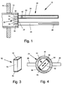
- the level sensor 10 shown in Fig. 1 for detection and / or monitoring the level in a container a tubular housing 12 which is in an opening of the container wall 14 at the level of the level to be monitored is attached.
- the end facing the inside of the container the housing 12 carries a mechanical vibration system 20.
- Das mechanical vibration system 20 is in the illustrated Example of a membrane 22 that is around its peripheral edge is connected to the edge of the tubular housing 12, and from two vibrating rods 24 and 25, each with one end are attached to the membrane 22 so that they are parallel to each other protrude from the membrane 22 into the interior of the container.
- each vibrating rod there are two diametrically opposite one another flat paddles 26 attached, extending from the free End of the vibrating rod over a part of its length extend and lie transverse to the plane that the axes of the contains two vibrating rods.
- these paddles is in 1 only one of the two paddles 26 of the vibrating rod 25 can be seen, while in Fig. 4 the two paddles 26 of the Vibrating rod 24 can be seen.
- the side of the membrane 22 facing away from the container is included an electromechanical transducer system 30 connected so is designed to be the mechanical vibration system 20 Can excite vibrations with its natural resonance frequency.
- the electromechanical transducer system contains 30 preferably an electromechanical excitation converter 31 and an electromechanical transducer 32.
- Each the two electromechanical transducers 31 and 32 is so trained that he a supplied alternating electrical signal (Alternating voltage or alternating current) into a mechanical Vibration and vice versa one acting on it mechanical vibration in an electrical alternating signal can convert.
- alternating electrical signal Alternating voltage or alternating current
- everyone Transducers 31 and 32 is a piezoelectric transducer that contains at least one piezoelectric element.
- a such a piezoelectric element is known to consist of a disk-shaped piezo crystal that lies between two Electrodes is arranged.
- the thickness of the piezo crystal changes depending on the on the electrodes generate applied voltage and vice versa mechanically forced changes in thickness of the piezo crystal an electrical voltage at the electrodes.
- the arousal converter 31 is connected to the membrane so that it due the thickness vibrations of his piezo crystal, which at Application of an electrical alternating voltage are generated, the diaphragm 22 vibrates on the two Vibrating rods 24 and 25 are transmitted so that these Vibrating rods counter to opposite mechanical vibrations run in their longitudinal direction, the plane of vibration the plane is the axis of the two vibrating bars contains and in Fig. 1 coincides with the plane of the drawing.
- the receiving transducer 32 is connected to the membrane 22 that he due to the mechanical vibration of the membrane 22nd an alternating electrical voltage between his two Electrodes generated.
- the piezoelectric transducers 31 and 32 are in a stack between membrane 22 and one Bridge 33 clamped by supports 34 and 35 in Distance from the membrane 22 is kept.
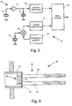
- the piezoelectric transducers 31 and 32 are in the in Fig. 2 shown way with a low frequency excitation and Evaluation circuit 36 connected in the housing 12th can be accommodated.
- One electrode each of each both transducers 31 and 32 are connected to a ground connection, for example through the membrane 22 and that Housing 12 can be formed.
- the other electrode of the Receive converter 32 is connected to the input of an amplifier 37 connected to the output of which the excitation converter 31 is connected is.
- the level sensor 10 lies with the two transducers 31 and 32, the mechanical vibration system 20 are coupled together in the feedback loop of the amplifier 37, which is designed so that the self-excitation is satisfied, so that the mechanical Vibration system via the two transducers 31 and 32 too Vibrations is excited with its natural resonance frequency.
- This natural resonance frequency is in the range of the audible acoustic frequencies, usually below 1000 Hz; it is a low frequency.
- the Natural resonance frequency of the mechanical vibration system 20 depends on whether the vibrating rods 24, 25 vibrate in air or immerse in a product.
- the natural resonance frequency is on the one hand due to the spring constant as the return spring acting membrane 22 and the other through the vibrating mass determined.
- the vibrating mass is there from the mass of the vibrating rods 24, 25 and from the mass of the taken from the vibrating rods during the oscillating movement surrounding medium. If the vibrating rods 24, 25 in Air, the entrained mass of air is negligible, and there is a natural resonance frequency one, essentially by the mass of the vibrating rods is determined. If, however, the vibrating rods 24, 25 in one If the product is immersed, the mass carried increases and accordingly, the natural resonance frequency of the mechanical Vibration system lower. This effect is through the paddles 26 reinforced because these paddles the carried Increase the mass of the product.
- a frequency discriminator 38 connected to the frequency of the Amplifier 37 output AC voltage, which is equal to Natural resonance frequency of the mechanical vibration system 20 is compared with a threshold. If this frequency is above the threshold, the output signal of Frequency discriminator 38 a first signal value indicating that the vibrating rods 24 and 25 swing in air and thus the level to be monitored has not been reached. If the frequency of the AC voltage emitted by the amplifier is below the threshold, the output signal the frequency discriminator 38 a second signal value, which indicates that the vibrating rods 24, 25 of the product are covered and thus the level to be monitored has been reached or exceeded.
- the structure and operation of the previously described low-frequency measuring system of the level sensor 20 are known for example from DE 33 36 991 A1.
- the in Fig. 1 level sensor differs of this prior art in that he also with a high-frequency measuring system.
- the sectional view of the vibrating rod 24 in FIG. 1 shows that this vibrating rod is designed as a hollow tube 40 is.
- the hollow tube 40 is on that facing away from the membrane 22 Closed end.
- an ultrasonic transducer 42 In the hollow tube 40 is close to the membrane 22 attached an ultrasonic transducer 42 so that it is high-frequency Transfer ultrasonic vibrations to the hollow tube can, which propagate as elastic waves in the hollow tube can use that as a waveguide for the elastic Serves waves.
- the elastic waves run along the Hollow tube 40 to the closed end at which it reflects and as echo waves to the ultrasonic transducer 42 return.
- the ultrasonic transducer 42 which acts as a transmitter transducer for transmission of elastic waves and as a receiving transducer for the reflected echo wave is used is preferably again a piezoelectric transducer that is suitable for high Frequencies is designed. 2 is also the excitation and Evaluation circuit 44 for the high-frequency measuring system of the Level sensor shown.
- a transmit pulse generator 45 generates short radio frequency pulses at periodic intervals, via a transceiver 46 to the ultrasonic transducer 42 are created, which are transmitted by each transmission pulse Transmission of an ultrasound pulse of the same frequency is excited.
- the one after each emission of an ultrasonic pulse received echo pulse is from the ultrasonic transducer 42 converted into an electrical receive pulse, the via the transceiver 46 of a transit time measurement circuit 47 is supplied.
- the transit time measuring circuit 47 determines the Duration between the transmission of a transmission pulse and the Arrival of the received pulse and it compares the measured Term with a threshold. If the measured Runtime is above the threshold, the output signal the transit time measuring circuit 47 a first signal value, which indicates that the hollow tube 40 is in air and thus the level to be monitored has not been reached. If in contrast, the measured transit time below the threshold the output signal of the transit time measuring circuit 47 a second signal value indicating that the hollow tube 40th is covered by the contents, and thus the one to be monitored Level is reached or exceeded.
- the duration of the ultrasonic pulses must be short compared to Term.
- the term in turn is because of the limited length of the vibrating rod 24 very short. Accordingly the frequency of the ultrasonic waves must be high; for example, it is on the order of 30 kHz.
- This utilization of the output signals of the two measuring systems can by a common signal processing circuit take place, for example, by a microcomputer 49 is formed.
- the vibrating rod 25 should be designed so that it is accurate the same vibration behavior as the vibrating rod 24 shows. So it is also a hollow tube with the same Dimensions like the hollow tube 40 of the vibrating rod 24, and at the point where the Ultrasonic transducer 42 is located in the vibrating rod 25 appropriate replacement mass attached.
- a further ultrasonic transducer in the vibrating rod 25 attach and with an associated excitation and evaluation circuit to connect, so that in addition to that low-frequency measuring system two high-frequency measuring systems available.
- the two high-frequency measuring systems can in this case be used for mutual control, which further increases the safety of the device becomes.
- FIG. 3 shows a perspective view of a piezoelectric Ultrasonic transducer 50, which is for use as Ultrasonic transducer 42 in the device of FIG. 1 is suitable and FIG. 4 shows a cross section through the ultrasound transducer 50 containing section of the hollow tube 40.
- the piezoelectric ultrasonic transducer 50 consists of a cuboidal piezo crystal 52, which is dimensioned so that it can be used in the hollow tube 40 and to each other diametrically opposite points on the wall of the hollow tube is present.
- Electrodes 54, 56 attached to which the electrical excitation pulses are applied be so that the piezo crystal 52 in diametrical directional thickness vibrations is offset, as in Fig. 4th is indicated by the double arrow. These vibrations are transferred to the wall of the hollow tube 40 and propagate in it as elastic waves.
- the piezoelectric transducer 50 can be in the hollow tube 40 be attached by gluing using an adhesive that the circular segment-shaped cavities 58 between the Electrodes 54, 56 and the inner surface of the wall of the hollow tube 40 fills and a rigid after curing Connection that gives the vibrations of the piezoelectric Converter 50 on the wall of the hollow tube 40th transmits.
- the piezo crystal 52 can also do so be shaped so that the electrodes 54, 56 carrying Surfaces have the same curvature as the inside surface of the wall of the hollow tube 40 and thus flat after installation of this inner surface. For example can be achieved in that the piezo crystal 52 from a circular disc is cut, its diameter is equal to the inside diameter of the hollow tube 40.
- the piezoelectric transducer 50 excites the tubular elastic waveguide formed by the hollow tube 40 to the oscillation mode shown in FIG. 5.
- the thickness vibrations of the piezo crystal 52 represented by the arrows F (t) cause the elliptical tube cross section Q 0 at a point in time t 0 , which after a half period at point in time t 1 results in an elliptical cross section Q 1 rotated by 90 ° and after a full period in Time t 2 passes into the elliptical cross section Q 2 rotated by 180 °, which again corresponds to the cross section Q 0 .
- This cross-sectional deformation propagates at the speed of propagation c of the ultrasonic waves along the tubular waveguide, so that the elliptical cross sections are rotated by 90 ° with respect to each other at half the wavelength ⁇ / 2.
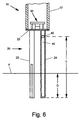
- the fill level sensor 10 can, as shown in FIG. 1 is horizontal at the level to be monitored be fixed in an opening of the container wall 14, it can but also, as shown in Fig. 6, in the vertical position be installed in the container.
- this enables high-frequency Measuring system in this case not only the finding whether the level to be monitored has been reached or not, but also the determination of the exact level, i.e. of the Height of the product surface F, in the area of the section L between the ultrasonic transducer 42 and the end of the through the vibrating rod 24 formed elastic waveguide.
- the ultrasonic waves generated by the ultrasonic transducer 42 propagate along the pipe wall at the speed of sound c determined by the material of the hollow pipe 40.
- the length D of the immersed section can be calculated from this become.
- the fill level sensor 60 has a tubular housing 62, which is at the level of the monitored Level is attached to a container wall 64, that it is complete or at least for the most part its length is inside the container.
- the low frequency Measuring system again contains a mechanical one Vibration system 70 with a membrane 72 that surrounds it Peripheral edge with the edge of the tubular housing 62 is connected, and with two oscillating rods 74, 75, the are each attached at one end to the membrane 72 and at their free ends two opposite each other Wear paddle 76.
- the vibrating rods 74, 75 are made in this embodiment made of flat metal plates.
- the in Inside of the housing side of the membrane 72 is with an electromechanical transducer system 78 connected so is designed to be the mechanical vibration system 70 Can excite vibrations with its natural resonance frequency.
- the converter system 78 is designed in the same way as the transducer system 30 of FIG. 1 and with an excitation and Evaluation circuit of the type shown in Fig. 2 connected.
- the low-frequency measuring system corresponds to the level sensor 60 of FIG. 7 the low-frequency measuring system of the level sensor 10 of Fig. 1, and it has the same Works like this.
- Fig. 8 shows a possible formation on one side of the piezo crystal Detect 82 attached electrodes 84.
- Electrodes 84a, 84b, 84c and 84d consist of four sectors 84a, 84b, 84c and 84d; the electrodes 84a diametrically opposite each other, 84c on the one hand and 84b, 84d on the other hand are each on the the same potential as the plus and minus signs is displayed.
- the one on the opposite side attached electrodes 86 are formed in the same way and wired.
- the piezo crystal is so radial polarized that under the influence of one to the Electrodes 84 and 86 applied an electrical voltage certain polarity to an elliptical cross section deformed, as exaggerated in Fig. 8, while he is applying an electrical voltage the opposite polarity to one rotated by 90 ° deformed elliptical cross section.
- Electrodes 84 and 86 are equipped with an excitation and evaluation circuit in Fig. 2 connected type, so that when creating of an electrical transmission pulse formed by the housing 62 tubular waveguide for ultrasonic vibrations of the vibration mode shown in FIG. 5 is excited. These ultrasonic vibrations plant themselves as elastic Ultrasonic waves in the housing wall up to that with the Membrane 72 connected end where they are reflected and as echo waves to the piezoelectric transducer 80 to return. By measuring the transit time of the ultrasonic pulses can be determined whether the housing 62 in Air or whether it is immersed in the contents.
- FIG. 9 Another embodiment of a level sensor 90 with a low-frequency measuring system and a high-frequency Measuring system is shown in Fig. 9.
- the fill level sensor 90 has, in the same way as the level sensors described above 10 and 60, a tubular housing 91 that carries a mechanical vibration system 92 that consists of a membrane 93 and two vibrating rods 94, 95 and one Transducer system 96 to vibrate at its natural resonant frequency is excited.
- the mechanical vibration system 92 forms in connection with an excitation and evaluation circuit the type shown in Fig. 2, the low-frequency measuring system.
- the level sensor 90 does not have an elastic one Waveguide for transmission of ultrasonic waves; much more the high-frequency measuring system is formed in that the area 97 between the oscillating rods 94 and 95 Membrane 92 is excited to vibrate at a frequency, which is much higher than the natural resonance frequency of the low frequency mechanical vibration system 92 and is preferred the natural resonance frequency of the membrane region 97 corresponds.
- This suggestion is preferably made by the same transducer system 96, which is also used to excite the natural resonance oscillation of the low-frequency mechanical vibration system 92 is used.
- the Monitoring of the fill level using the high-frequency measuring system does not take place in this case by a runtime measurement, but by evaluating the natural resonance frequency of the Membrane area 97, which if the membrane area of Is covered, is lower than if the Membrane region 97 vibrates in air.
Landscapes
- Physics & Mathematics (AREA)
- Acoustics & Sound (AREA)
- Electromagnetism (AREA)
- Thermal Sciences (AREA)
- Fluid Mechanics (AREA)
- General Physics & Mathematics (AREA)
- Measurement Of Levels Of Liquids Or Fluent Solid Materials (AREA)
Priority Applications (6)
| Application Number | Priority Date | Filing Date | Title |
|---|---|---|---|
| EP97116486A EP0903563B1 (fr) | 1997-09-22 | 1997-09-22 | Dispositif pour la détection et/ou la surveillance d'un niveau prédéterminé dans un récipient |
| DE59712760T DE59712760D1 (de) | 1997-09-22 | 1997-09-22 | Vorrichtung zur Feststellung und/oder Überwachung eines vorbestimmten Füllstands in einem Behälter |
| US09/156,726 US5966983A (en) | 1997-09-22 | 1998-09-17 | Assembly for sensing and/or monitoring a predetermined level in a vessel |
| JP10264938A JP2960726B2 (ja) | 1997-09-22 | 1998-09-18 | 充填レベルを測定および/または監視する装置 |
| HU9802125A HU220827B1 (hu) | 1997-09-22 | 1998-09-21 | Berendezés tartály előre meghatározott töltési szintjének megállapítására és/vagy megfigyelésére |
| CA002247485A CA2247485C (fr) | 1997-09-22 | 1998-09-21 | Assemblage pour detecter ou surveiller un niveau preetabli dans un recipient |
Applications Claiming Priority (1)
| Application Number | Priority Date | Filing Date | Title |
|---|---|---|---|
| EP97116486A EP0903563B1 (fr) | 1997-09-22 | 1997-09-22 | Dispositif pour la détection et/ou la surveillance d'un niveau prédéterminé dans un récipient |
Publications (2)
| Publication Number | Publication Date |
|---|---|
| EP0903563A1 true EP0903563A1 (fr) | 1999-03-24 |
| EP0903563B1 EP0903563B1 (fr) | 2006-11-02 |
Family
ID=8227388
Family Applications (1)
| Application Number | Title | Priority Date | Filing Date |
|---|---|---|---|
| EP97116486A Expired - Lifetime EP0903563B1 (fr) | 1997-09-22 | 1997-09-22 | Dispositif pour la détection et/ou la surveillance d'un niveau prédéterminé dans un récipient |
Country Status (6)
| Country | Link |
|---|---|
| US (1) | US5966983A (fr) |
| EP (1) | EP0903563B1 (fr) |
| JP (1) | JP2960726B2 (fr) |
| CA (1) | CA2247485C (fr) |
| DE (1) | DE59712760D1 (fr) |
| HU (1) | HU220827B1 (fr) |
Cited By (9)
| Publication number | Priority date | Publication date | Assignee | Title |
|---|---|---|---|---|
| DE10022891A1 (de) * | 2000-05-10 | 2001-11-15 | Endress Hauser Gmbh Co | Vorrichtung zur Feststellung und/oder Überwachung des Füllstandes eines Füllguts in einem Behälter |
| EP1373841A1 (fr) * | 2001-03-28 | 2004-01-02 | Endress + Hauser GmbH + Co. | Dispositif pour la determination ou la surveillance d'un niveau de remplissage predefini dans un contenant |
| DE102016118445A1 (de) | 2016-09-29 | 2018-03-29 | Vega Grieshaber Kg | Vibrationssensor und Verfahren zum Betreiben eines Vibrationssensors |
| DE102005009580B4 (de) * | 2005-02-28 | 2021-02-04 | Endress+Hauser SE+Co. KG | Verfahren und entsprechende Vorrichtung zur Bestimmung und/oder Überwachung einer Prozessgrösse |
| WO2021165011A1 (fr) * | 2020-02-17 | 2021-08-26 | Endress+Hauser SE+Co. KG | Capteur à vibrations |
| WO2021170339A1 (fr) * | 2020-02-27 | 2021-09-02 | Endress+Hauser SE+Co. KG | Multicapteur vibronique |
| WO2023030754A1 (fr) * | 2021-08-31 | 2023-03-09 | Endress+Hauser SE+Co. KG | Multicapteur vibronique |
| DE102022133730A1 (de) * | 2022-12-16 | 2024-06-27 | Endress+Hauser SE+Co. KG | Vorrichtung zur Bestimmung und/oder Überwachung zumindest einer Prozessgröße eines Mediums |
| DE102024101264A1 (de) * | 2024-01-17 | 2025-07-17 | Endress+Hauser SE+Co. KG | Vibrationssensor mit Propellerantrieb |
Families Citing this family (19)
| Publication number | Priority date | Publication date | Assignee | Title |
|---|---|---|---|---|
| US6138507A (en) * | 1997-04-30 | 2000-10-31 | Endress + Hauser Gmbh + Co. | Apparatus for establishing and/or monitoring a predetermined filling level in a container through controlled transducer phase and impedance |
| DE10203461A1 (de) * | 2002-01-28 | 2003-08-14 | Grieshaber Vega Kg | Schwingungsgrenzstandsensor |
| US6931929B2 (en) * | 2002-04-10 | 2005-08-23 | Akebono Brake Industry Co., Ltd. | Filler detection method and filler detection device |
| DE10250065A1 (de) * | 2002-10-25 | 2004-05-06 | Endress + Hauser Flowtec Ag, Reinach | Prozeß-Meßgerät |
| DE102010003733B4 (de) * | 2010-04-08 | 2020-08-13 | Endress+Hauser SE+Co. KG | Verfahren zur Detektion von Gasblasen in einem flüssigen Medium |
| DE102010003734B4 (de) * | 2010-04-08 | 2021-06-17 | Endress+Hauser SE+Co. KG | Verfahren zur Detektion von Gasblasen in einem flüssigen Medium |
| DE102010038535A1 (de) * | 2010-07-28 | 2012-02-02 | Endress + Hauser Gmbh + Co. Kg | Vorrichtung zur Bestimmung und/oder Überwachung eines vorgegebenen Füllstands |
| DE102012100728A1 (de) | 2012-01-30 | 2013-08-01 | Endress + Hauser Gmbh + Co. Kg | Vorrichtung zur Bestimmung und/oder Überwachung mindestens einer Prozessgröße |
| JP2013156194A (ja) * | 2012-01-31 | 2013-08-15 | Toshiba Corp | 液面レベル計測装置及び方法 |
| DE102012102589A1 (de) * | 2012-03-26 | 2013-09-26 | Endress + Hauser Gmbh + Co. Kg | Vorrichtung zur Überwachung eines vorbestimmten Füllstands |
| DE102015114286A1 (de) * | 2015-08-27 | 2017-03-02 | Endress + Hauser Flowtec Ag | Vibronische Vorrichtung zur Bestimmung oder Überwachung einer Prozessgröße |
| CN107796929A (zh) * | 2017-11-06 | 2018-03-13 | 华侨大学 | 弹性波辅助水泥注浆止水模型试验装置 |
| RU2700038C2 (ru) | 2018-02-14 | 2019-09-12 | Александр Петрович Демченко | Акустический волновод |
| DE102019116150A1 (de) | 2019-06-13 | 2020-12-17 | Endress+Hauser SE+Co. KG | Vibronischer Multisensor |
| CN112525291B (zh) * | 2020-12-16 | 2024-06-14 | 深圳市纵维立方科技有限公司 | 打印设备及液面深度检测方法 |
| DE102021126092A1 (de) | 2021-10-07 | 2023-04-13 | Endress+Hauser SE+Co. KG | Vibronischer Multisensor |
| US20230189652A1 (en) * | 2021-12-10 | 2023-06-15 | Measurement Specialities, Inc. | Sensor Having A Piezoelectric Element |
| CN114812748B (zh) * | 2022-05-16 | 2025-05-30 | 国家石油天然气管网集团有限公司 | 一种可快速拆卸的音叉液位开关 |
| DE102023119700A1 (de) * | 2023-07-25 | 2025-01-30 | Endress+Hauser SE+Co. KG | Vibrationssensor |
Citations (5)
| Publication number | Priority date | Publication date | Assignee | Title |
|---|---|---|---|---|
| EP0070334A1 (fr) * | 1981-07-17 | 1983-01-26 | The Marconi Company Limited | Appareil de mesure du niveau d'un liquide |
| DE3336991A1 (de) * | 1983-10-11 | 1985-05-02 | Endress U. Hauser Gmbh U. Co, 7867 Maulburg | Vorrichtung zur feststellung und/oder ueberwachung eines vorbestimmten fuellstands in einem behaelter |
| EP0409732A1 (fr) * | 1989-07-20 | 1991-01-23 | Auxitrol S.A. | Détecteur de la présence d'un liquide à guide composite d'ondes élastiques |
| WO1995016190A1 (fr) * | 1993-12-09 | 1995-06-15 | Kay-Ray/Sensall, Inc. | Instrument de niveau a ultrasons fonctionnant sur deux frequences |
| GB2290142A (en) * | 1994-06-08 | 1995-12-13 | Bindicator Co | Ultrasonic material level measurement |
Family Cites Families (3)
| Publication number | Priority date | Publication date | Assignee | Title |
|---|---|---|---|---|
| US5155472A (en) * | 1983-07-29 | 1992-10-13 | Introtek International, Inc. | Contact type liquid level sensing system |
| US4901245A (en) * | 1987-12-01 | 1990-02-13 | Moore Technologies, Inc. | Nonintrusive acoustic liquid level sensor |
| US5608164A (en) * | 1995-07-27 | 1997-03-04 | The Babcock & Wilcox Company | Electromagnetic acoustic transducer (EMAT) for ultrasonic inspection of liquids in containers |
-
1997
- 1997-09-22 DE DE59712760T patent/DE59712760D1/de not_active Expired - Fee Related
- 1997-09-22 EP EP97116486A patent/EP0903563B1/fr not_active Expired - Lifetime
-
1998
- 1998-09-17 US US09/156,726 patent/US5966983A/en not_active Expired - Fee Related
- 1998-09-18 JP JP10264938A patent/JP2960726B2/ja not_active Expired - Fee Related
- 1998-09-21 CA CA002247485A patent/CA2247485C/fr not_active Expired - Fee Related
- 1998-09-21 HU HU9802125A patent/HU220827B1/hu not_active IP Right Cessation
Patent Citations (5)
| Publication number | Priority date | Publication date | Assignee | Title |
|---|---|---|---|---|
| EP0070334A1 (fr) * | 1981-07-17 | 1983-01-26 | The Marconi Company Limited | Appareil de mesure du niveau d'un liquide |
| DE3336991A1 (de) * | 1983-10-11 | 1985-05-02 | Endress U. Hauser Gmbh U. Co, 7867 Maulburg | Vorrichtung zur feststellung und/oder ueberwachung eines vorbestimmten fuellstands in einem behaelter |
| EP0409732A1 (fr) * | 1989-07-20 | 1991-01-23 | Auxitrol S.A. | Détecteur de la présence d'un liquide à guide composite d'ondes élastiques |
| WO1995016190A1 (fr) * | 1993-12-09 | 1995-06-15 | Kay-Ray/Sensall, Inc. | Instrument de niveau a ultrasons fonctionnant sur deux frequences |
| GB2290142A (en) * | 1994-06-08 | 1995-12-13 | Bindicator Co | Ultrasonic material level measurement |
Cited By (13)
| Publication number | Priority date | Publication date | Assignee | Title |
|---|---|---|---|---|
| DE10022891A1 (de) * | 2000-05-10 | 2001-11-15 | Endress Hauser Gmbh Co | Vorrichtung zur Feststellung und/oder Überwachung des Füllstandes eines Füllguts in einem Behälter |
| RU2239794C2 (ru) * | 2000-05-10 | 2004-11-10 | Эндресс + Хаузер Гмбх + Ко. Кг | Устройство для определения и/или контроля уровня загруженного материала в емкости |
| EP1373841A1 (fr) * | 2001-03-28 | 2004-01-02 | Endress + Hauser GmbH + Co. | Dispositif pour la determination ou la surveillance d'un niveau de remplissage predefini dans un contenant |
| DE102005009580B4 (de) * | 2005-02-28 | 2021-02-04 | Endress+Hauser SE+Co. KG | Verfahren und entsprechende Vorrichtung zur Bestimmung und/oder Überwachung einer Prozessgrösse |
| DE102016118445A1 (de) | 2016-09-29 | 2018-03-29 | Vega Grieshaber Kg | Vibrationssensor und Verfahren zum Betreiben eines Vibrationssensors |
| US12181316B2 (en) | 2020-02-17 | 2024-12-31 | Endress+Hauser SE+Co. KG | Vibronic sensor |
| WO2021165011A1 (fr) * | 2020-02-17 | 2021-08-26 | Endress+Hauser SE+Co. KG | Capteur à vibrations |
| WO2021170339A1 (fr) * | 2020-02-27 | 2021-09-02 | Endress+Hauser SE+Co. KG | Multicapteur vibronique |
| US12203888B2 (en) | 2020-02-27 | 2025-01-21 | Endress+Hauser SE+Co. KG | Vibronic mulitsensor |
| WO2023030754A1 (fr) * | 2021-08-31 | 2023-03-09 | Endress+Hauser SE+Co. KG | Multicapteur vibronique |
| DE102022133730A1 (de) * | 2022-12-16 | 2024-06-27 | Endress+Hauser SE+Co. KG | Vorrichtung zur Bestimmung und/oder Überwachung zumindest einer Prozessgröße eines Mediums |
| DE102024101264A1 (de) * | 2024-01-17 | 2025-07-17 | Endress+Hauser SE+Co. KG | Vibrationssensor mit Propellerantrieb |
| WO2025153289A1 (fr) | 2024-01-17 | 2025-07-24 | Endress+Hauser SE+Co. KG | Capteur de vibrations présentant un entraînement d'hélice |
Also Published As
| Publication number | Publication date |
|---|---|
| JP2960726B2 (ja) | 1999-10-12 |
| HUP9802125A2 (hu) | 1999-04-28 |
| HU9802125D0 (en) | 1998-11-30 |
| US5966983A (en) | 1999-10-19 |
| JPH11153472A (ja) | 1999-06-08 |
| CA2247485A1 (fr) | 1999-03-22 |
| HUP9802125A3 (en) | 2000-03-28 |
| CA2247485C (fr) | 2001-07-31 |
| HU220827B1 (hu) | 2002-05-28 |
| EP0903563B1 (fr) | 2006-11-02 |
| DE59712760D1 (de) | 2006-12-14 |
Similar Documents
| Publication | Publication Date | Title |
|---|---|---|
| EP0903563B1 (fr) | Dispositif pour la détection et/ou la surveillance d'un niveau prédéterminé dans un récipient | |
| EP0644999B1 (fr) | Indicateur de niveau | |
| EP0871019B1 (fr) | Procédé et dispositif pour la détection d'un remplissage excessif à une mesure de niveau d'un liquide dans un récipient selon le procédé du temps de transit des impulsions | |
| DE60001445T2 (de) | Auf Resonanz basierendes Druckwandlersystem | |
| DE10045375C2 (de) | Medizinisches Instrument | |
| EP3577427B1 (fr) | Compteur à ultrasons et procédé d'acquisition d'une grandeur de débit | |
| DE1773815B2 (de) | Vorrichtung zur Feststellung des Erreichens eines vorbestimmten Füllstands in einem Behälter | |
| DE2906704A1 (de) | Ultraschalltransponder | |
| DE3411446A1 (de) | Verfahren und sensor zum ermitteln einer trennflaeche einer fluessigkeit in einem behaelter | |
| EP0452531A1 (fr) | Dispositif électrique pour mesurer le temps de propagation d'un signal électrique | |
| EP2440888B1 (fr) | Procédé de mesure d'un mesurande | |
| DE19720519C2 (de) | Vorrichtung zur Feststellung und/oder Überwachung eines Füllstandes eines Mediums in einem Behälter | |
| EP0089336A1 (fr) | Mesure du niveau de remplissage. | |
| EP3910296A1 (fr) | Procédé de fonctionnement d'un dispositif de mesure et dispositif de mesure | |
| EP0875742B1 (fr) | Dispositif pour la détermination et/ou la surveillance d'un niveau prédéterminé dans un réservoir | |
| DE102008050326A1 (de) | Vorrichtung zur Bestimmung und/oder Überwachung einer Prozessgröße eines Mediums | |
| EP0882958A1 (fr) | Procédé et dispositif pour surveiller un niveau prédeterminé de remplissage dans un récipient | |
| EP1800093B1 (fr) | Dispositif pour determiner et/ou controler une grandeur de processus d'un milieu | |
| DE3912038C2 (fr) | ||
| DE102010003733A1 (de) | Verfahren zur Detektion von Gasblasen in einem flüssigen Medium | |
| EP0875740B1 (fr) | Dispositif pour la détermination et/ou la surveillance d'un niveau prédéterminé dans un réservoir | |
| EP1358476A2 (fr) | Capteur ultrasonique pour la commande de processus pour le soudage par resistance par points | |
| DE102007027816A1 (de) | Vorrichtung zur Ermittlung und Überwachung des Füllstands eines Füllguts in einem Behälter | |
| EP0423143B1 (fr) | Indicateur de niveau | |
| DE3219626C2 (de) | Vorrichtung zur Feststellung des Erreichens eines vorbestimmten Füllstandes in einem Behälter |
Legal Events
| Date | Code | Title | Description |
|---|---|---|---|
| PUAI | Public reference made under article 153(3) epc to a published international application that has entered the european phase |
Free format text: ORIGINAL CODE: 0009012 |
|
| AK | Designated contracting states |
Kind code of ref document: A1 Designated state(s): DE FR GB IT NL |
|
| 17P | Request for examination filed |
Effective date: 19990729 |
|
| AKX | Designation fees paid |
Free format text: DE FR GB IT NL |
|
| RAP1 | Party data changed (applicant data changed or rights of an application transferred) |
Owner name: ENDRESS + HAUSER GMBH + CO.KG. |
|
| GRAP | Despatch of communication of intention to grant a patent |
Free format text: ORIGINAL CODE: EPIDOSNIGR1 |
|
| GRAS | Grant fee paid |
Free format text: ORIGINAL CODE: EPIDOSNIGR3 |
|
| GRAA | (expected) grant |
Free format text: ORIGINAL CODE: 0009210 |
|
| AK | Designated contracting states |
Kind code of ref document: B1 Designated state(s): DE FR GB IT NL |
|
| PG25 | Lapsed in a contracting state [announced via postgrant information from national office to epo] |
Ref country code: NL Free format text: LAPSE BECAUSE OF FAILURE TO SUBMIT A TRANSLATION OF THE DESCRIPTION OR TO PAY THE FEE WITHIN THE PRESCRIBED TIME-LIMIT Effective date: 20061102 Ref country code: IT Free format text: LAPSE BECAUSE OF FAILURE TO SUBMIT A TRANSLATION OF THE DESCRIPTION OR TO PAY THE FEE WITHIN THE PRESCRIBED TIME-LIMIT;WARNING: LAPSES OF ITALIAN PATENTS WITH EFFECTIVE DATE BEFORE 2007 MAY HAVE OCCURRED AT ANY TIME BEFORE 2007. THE CORRECT EFFECTIVE DATE MAY BE DIFFERENT FROM THE ONE RECORDED. Effective date: 20061102 |
|
| REG | Reference to a national code |
Ref country code: GB Ref legal event code: FG4D Free format text: NOT ENGLISH |
|
| REF | Corresponds to: |
Ref document number: 59712760 Country of ref document: DE Date of ref document: 20061214 Kind code of ref document: P |
|
| NLV1 | Nl: lapsed or annulled due to failure to fulfill the requirements of art. 29p and 29m of the patents act | ||
| GBV | Gb: ep patent (uk) treated as always having been void in accordance with gb section 77(7)/1977 [no translation filed] |
Effective date: 20061102 |
|
| EN | Fr: translation not filed | ||
| PLBE | No opposition filed within time limit |
Free format text: ORIGINAL CODE: 0009261 |
|
| STAA | Information on the status of an ep patent application or granted ep patent |
Free format text: STATUS: NO OPPOSITION FILED WITHIN TIME LIMIT |
|
| 26N | No opposition filed |
Effective date: 20070803 |
|
| PG25 | Lapsed in a contracting state [announced via postgrant information from national office to epo] |
Ref country code: GB Free format text: LAPSE BECAUSE OF FAILURE TO SUBMIT A TRANSLATION OF THE DESCRIPTION OR TO PAY THE FEE WITHIN THE PRESCRIBED TIME-LIMIT Effective date: 20061102 |
|
| PG25 | Lapsed in a contracting state [announced via postgrant information from national office to epo] |
Ref country code: FR Free format text: LAPSE BECAUSE OF FAILURE TO SUBMIT A TRANSLATION OF THE DESCRIPTION OR TO PAY THE FEE WITHIN THE PRESCRIBED TIME-LIMIT Effective date: 20070615 |
|
| PG25 | Lapsed in a contracting state [announced via postgrant information from national office to epo] |
Ref country code: DE Free format text: LAPSE BECAUSE OF NON-PAYMENT OF DUE FEES Effective date: 20080401 |
|
| PG25 | Lapsed in a contracting state [announced via postgrant information from national office to epo] |
Ref country code: FR Free format text: LAPSE BECAUSE OF FAILURE TO SUBMIT A TRANSLATION OF THE DESCRIPTION OR TO PAY THE FEE WITHIN THE PRESCRIBED TIME-LIMIT Effective date: 20061102 |