EP0903658B1 - Manette de commande multifonctionnelle - Google Patents
Manette de commande multifonctionnelle Download PDFInfo
- Publication number
- EP0903658B1 EP0903658B1 EP19980105702 EP98105702A EP0903658B1 EP 0903658 B1 EP0903658 B1 EP 0903658B1 EP 19980105702 EP19980105702 EP 19980105702 EP 98105702 A EP98105702 A EP 98105702A EP 0903658 B1 EP0903658 B1 EP 0903658B1
- Authority
- EP
- European Patent Office
- Prior art keywords
- guide piece
- base plate
- operator control
- guide
- activation knob
- Prior art date
- Legal status (The legal status is an assumption and is not a legal conclusion. Google has not performed a legal analysis and makes no representation as to the accuracy of the status listed.)
- Expired - Lifetime
Links
- 230000004913 activation Effects 0.000 claims 11
- 235000019640 taste Nutrition 0.000 description 3
- 230000015572 biosynthetic process Effects 0.000 description 2
- 238000005286 illumination Methods 0.000 description 2
- 230000001419 dependent effect Effects 0.000 description 1
- 230000000881 depressing effect Effects 0.000 description 1
- 230000000994 depressogenic effect Effects 0.000 description 1
- 230000005484 gravity Effects 0.000 description 1
- 230000010354 integration Effects 0.000 description 1
Images
Classifications
-
- G—PHYSICS
- G05—CONTROLLING; REGULATING
- G05G—CONTROL DEVICES OR SYSTEMS INSOFAR AS CHARACTERISED BY MECHANICAL FEATURES ONLY
- G05G9/00—Manually-actuated control mechanisms provided with one single controlling member co-operating with two or more controlled members, e.g. selectively, simultaneously
- G05G9/02—Manually-actuated control mechanisms provided with one single controlling member co-operating with two or more controlled members, e.g. selectively, simultaneously the controlling member being movable in different independent ways, movement in each individual way actuating one controlled member only
- G05G9/04—Manually-actuated control mechanisms provided with one single controlling member co-operating with two or more controlled members, e.g. selectively, simultaneously the controlling member being movable in different independent ways, movement in each individual way actuating one controlled member only in which movement in two or more ways can occur simultaneously
- G05G9/047—Manually-actuated control mechanisms provided with one single controlling member co-operating with two or more controlled members, e.g. selectively, simultaneously the controlling member being movable in different independent ways, movement in each individual way actuating one controlled member only in which movement in two or more ways can occur simultaneously the controlling member being movable by hand about orthogonal axes, e.g. joysticks
- G05G2009/04703—Mounting of controlling member
- G05G2009/04711—Mounting of controlling member with substantially hemispherical bearing part forced into engagement, e.g. by a spring
-
- G—PHYSICS
- G05—CONTROLLING; REGULATING
- G05G—CONTROL DEVICES OR SYSTEMS INSOFAR AS CHARACTERISED BY MECHANICAL FEATURES ONLY
- G05G9/00—Manually-actuated control mechanisms provided with one single controlling member co-operating with two or more controlled members, e.g. selectively, simultaneously
- G05G9/02—Manually-actuated control mechanisms provided with one single controlling member co-operating with two or more controlled members, e.g. selectively, simultaneously the controlling member being movable in different independent ways, movement in each individual way actuating one controlled member only
- G05G9/04—Manually-actuated control mechanisms provided with one single controlling member co-operating with two or more controlled members, e.g. selectively, simultaneously the controlling member being movable in different independent ways, movement in each individual way actuating one controlled member only in which movement in two or more ways can occur simultaneously
- G05G9/047—Manually-actuated control mechanisms provided with one single controlling member co-operating with two or more controlled members, e.g. selectively, simultaneously the controlling member being movable in different independent ways, movement in each individual way actuating one controlled member only in which movement in two or more ways can occur simultaneously the controlling member being movable by hand about orthogonal axes, e.g. joysticks
- G05G2009/0474—Manually-actuated control mechanisms provided with one single controlling member co-operating with two or more controlled members, e.g. selectively, simultaneously the controlling member being movable in different independent ways, movement in each individual way actuating one controlled member only in which movement in two or more ways can occur simultaneously the controlling member being movable by hand about orthogonal axes, e.g. joysticks characterised by means converting mechanical movement into electric signals
- G05G2009/04744—Switches
Definitions
- the invention is based on a multifunctional control element according to the preamble of the main claim.
- the US 4,408,103 shows a joystick, with an operating lever and with a lever connected to the plate.
- a pivoting of the operating lever causes the plate presses down a piece of rubber and thus produces an electrical line to a arranged on a circuit board contact.
- the layout DE 1 268 251 shows as the closest prior art, a switching device with a pivotable shift rod, in which a pyramid-shaped sliding body is mounted on an axle. Between the slider and a support body, a single spring is disposed concentrically around the shift rod. The spring is fixedly mounted with its one end centrally to the center of gravity in a housing and arranged immovably with its other end in the slider.
- the multifunctional operating element according to the invention with the features of the main claim has the advantage that a bearing on the opposite side of the actuating button of the guide piece is provided, in which the Axis is stored. In this way, no vertical pressure movement of the control element is possible, so that a simultaneous contacting of more than one contact can be prevented.
- Another advantage is that a return spring is provided which cooperates with the axis so that a pivoted base plate springs back into an initial position. In this way, the ease of use for the user is increased because he does not have to return the control itself to its original position. Furthermore, it is prevented that a contact or push-button operated too long and possibly an unwanted function value is set in this way.
- a particular advantage is that the distance between the bearing and the base plate exceeds a predetermined value. In this way, a feltverschwenkwinkel the control element is required for contacting a contact by means of the base plate, so that the positions of the control element for contacting the individual contacts are clearly separated.
- tact switches are arranged on the printed circuit board, by the actuation of which the contacting of the contacts takes place on the printed circuit board and that the key switches can be actuated by pivoting the base plate.
- the key switches can be actuated by pivoting the base plate.
- the guide piece for each key switch has a guide slot in which the axis of the control element is feasible and that the guide slots are arranged in the guide piece, that upon pivoting of the base plate of the respective associated key switch can be actuated. In this way, a defined and unambiguous movement of the operating element for actuating a respective contact or key switch is possible, so that incorrect operations on the part of the user, which lead to no contact, are excluded.
- the guide piece is formed in the region of the guide slots on a side facing the operating knob spherical segment. In this way, a support for the operating knob is realized, which prevents as well as the storage of the axis that the control element can be pressed on the operating button to the circuit board and at the same time several contacts or push-button could be operated by the base plate.
- the guide piece on a side facing away from the actuating knob has a recess and that the base plate is formed on a side facing the operating knob spherical segment.
- the base plate can be guided in the recess of the guide piece, so that the operation further simplified for the user and the ease of use is increased.
- a more stable storage of the control element in the front panel is realized in this way.
- the operating knob is plugged onto the axis and beveled on a side facing the guide piece. In this way, the operating knob can be replaced in a simple manner and attach an individually adapted to the needs and tastes of the user operating knob on the axle.
- the operating knob can slide slidably on pivoting of the control element on the guide piece, so that the pivoting movement of the control element supported by the guide piece and thus the ease of use is increased.
- the guide piece is designed as a light guide body and that a light source is provided for illuminating the guide piece. In this way, the operation of the control is simplified in the dark for the user.
- the guide piece is covered by a preferably attachable cover plate, that the cover plate does not have in the region of the guide slots in each case a recess.
- the ease of use for the user is further increased because the possible directions of actuation of the operating element through the recesses of the cover plate are already displayed. This also applies to darkness and illumination of the guide piece by a light source, since the cover plate is made opaque.
- Another advantage is that the user can choose the cover plate individually according to his needs and his taste, since the cover plate is attachable to the guide piece and thus replaceable.
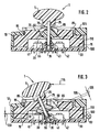
- FIG. 2 shows a side view of the mounted in the front panel operating element in a starting position
- Figure 3 is a side view of a mounted in the front panel operating element in a pivoted position.
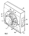
- 5 denotes an actuating knob of a multifunctional operating element 1 designed in the form of a joystick.
- the multifunctional operating element 1 is held and guided by a guide piece 15 fixedly connected to a front panel 10.
- the guide piece 15 protrudes according to Figure 2 or Figure 3 in a first opening 95 on a user interface 105 of the front panel 10 from the inside of the front panel 10.
- the guide piece 15 four mutually perpendicular guide slots, which together form a cross-shaped slot.
- a first guide slot 51 and a second guide slot 52 are shown in Figure 1 for reasons of perspective view.
- the guide piece 15 is formed on a segment 5 facing the actuating button 5 spherical segment.
- the guide piece 15 can be covered by a cover plate 85 which can be plugged into the first opening 95, wherein the cover plate 85 can be opaque and has a recess 91, 92, 93, 94 in the region of the guide slots.
- the operating element 1 can be guided by means of the actuating button 5 in the guide slots of the guide piece 15, wherein a user the possible operating directions of the operating element 1 through the recesses 91, 92, 93, 94, which together enlarge the cross shape of the guide slots in the region of the user interface 105, be identified.
- the associated actuating direction can still be illustrated by one or more applied arrowheads.
- the front panel 10 is mounted on a printed circuit board 30 and laterally has a second opening 100, via which the guide piece 15 can be illuminated via a light source 80 according to FIG.
- the guide piece 15 As a light guide, this leads to a corresponding illumination of the recesses 91, 92, 93, 94 of the cover plate 85 recessed surfaces of the guide piece 15, so that the user the possible operating directions are made even in the dark.
- FIG. 1 shows the operating element 1 in a starting position.
- the starting position is characterized in that the operating element 1 is not pivoted in one of the four possible directions of actuation and is located in the center of the cross formed by the guide slots.
- the mounted in the front panel 10 control element 1 is shown in a side view, wherein it is also in the starting position.
- the operating knob 5 is attached to an axis 25 and beveled on a guide piece 15 facing side 75 and about the axis 25 around.
- the operating element 1 has on a side opposite the operating knob 5 side of the guide piece 15, a base plate 20, wherein the actuating button 5 and the base plate 20 are fixedly connected to each other via the axis 25.
- the guide piece 15 has a recess 65 on a side facing away from the actuating button 5.
- the base plate 20 is formed on a side facing the operating knob 5 side 70 spherical segment.
- the base plate 20 On a side facing away from the operating knob 5, the base plate 20 has a chamfer 110 extending annularly around the axis 25.
- the axis 25 is mounted on the actuating button 5 opposite side of the guide piece 15 in a bearing 35 of the circuit board 30. The distance between the bearing 35 and the base plate 20 should exceed a predetermined value.
- the axis 25 is guided in the guide slots of the guide piece 15, so that it comes depending on the direction of actuation upon actuation of the control element 1 to pivot the base plate 20 via the operating knob 5 in one of the four possible directions of actuation.
- Each actuation direction or each guide slot is assigned to a contact pair on the printed circuit board 30, which can be contacted by actuation of a pushbutton switch or electrically conductively connected to one another.
- a push-button switch is provided, which is depressed by a corresponding pivoting of the control element 1 from the base plate 20 for contacting.
- the required pivot angle for depressing the corresponding key switch depends on the distance between the bearing 35 and the base plate 20 and the bevel 110 of the Sokkelplatte 20.
- three push-buttons 41, 42, 43 are shown due to the lateral representation in Figure 2 and Figure 3 respectively.
- the key switches are also arranged on the circuit board 30.
- the axis 25 is encompassed by a return spring 55 which cooperates with the axis 25 so that a pivoted base plate 20 springs back to the starting position.
- control element 1 is shown in a different from its initial position, pivoted position.
- a lateral force introduction on the actuating button 5 is represented by an arrow marked with the reference numeral 115.
- the actuating knob 5 slides with its bevel on its side facing the guide piece 15 side 75 along the actuating button 5 facing, in the region of the guide slots ball segment shaped side 60 of the guide piece 15.
- the base plate 20 with its the operating knob 5 facing spherical segment-shaped side 70th guided within the recess 65 along the guide piece 15.
- the lateral introduction of force on the operating knob 5 leads to a pivot angle of the operating element 1, which leads to a depression of a first key switch 41 on the circuit board 30 through the base plate 20, wherein a switching stroke 120 is realized, which arranged for contacting the corresponding on the circuit board 30 Contact surface pair via a contact of the corresponding first key switch 41 leads. Due to the chamfer 110 of the Sokkelplatte 20 this lies on depression of the corresponding key switch area on its surface, so that no significant wear of the base plate 20 and the corresponding key switch takes place. In the illustrated in Figure 3 pivoted position of the control element 1, the return spring 55 is laterally compressed by a spring 125, which causes the required for the return of the control element 1 in its initial position restoring force.
- the return spring 55 also serves to compensate for tolerance variations in the dimensions of the guide slots and the base plate 20 and the guide piece 15 and its recess 65 in particular.
- the front panel 10 may be part of an operating front of a car radio. It can be done in the formation of the guide piece 15 as a light guide an integration of the guide piece 15 in a total light guide the front of the car radio.
- the operating knob 5 is attachable to the axis 25 and the cover plate 85 is inserted into the first opening 95 of the front panel 10, so that the operating knob 5 and the cover plate 85 can be replaced depending on individual needs and the taste of the user.
- the multifunctional operating element 1 can be used by means of the actuation of the four push-buttons for selecting operating functions, for example on an operating menu and / or for setting functional values of an operating function, such as the volume and the balance, in particular in a car radio. Due to the multifunctionality of the control element 1, the space for the otherwise required corresponding individual control elements can be saved on the front panel of such a device and increase the clarity for the user.
- the operating element 1 can be used with all electrical devices in which operating functions and / or function values of operating functions can be set.
Landscapes
- Physics & Mathematics (AREA)
- General Physics & Mathematics (AREA)
- Engineering & Computer Science (AREA)
- Automation & Control Theory (AREA)
- Switches With Compound Operations (AREA)
Claims (10)
- Elément de commande multifonctionnel (1) comportant un bouton de manoeuvre (5) tenu et guidé par une pièce de guidage (15) reliée à une plaque frontale (10) et ayant une plaque formant socle (20) sur le côté de la pièce de guidage (15), à l'opposé du bouton de manoeuvre (5), le bouton de manoeuvre (5) et la plaque formant socle (20) étant reliés par un axe (25),
et par basculement de la plaque formant socle (20) avec le bouton de manoeuvre (5) on relie des contacts prévus sur une plaque de circuit (30) et
un palier (35) prévu sur le côté de la pièce de guidage (15) à l'opposé du bouton de manoeuvre (5), recevant l'axe (25),
caractérisé par
un ressort de rappel (55) entourant l'axe (25) et coopérant avec cet axe (25) pour rappeler élastiquement la plaque formant socle (20), basculée, pour revenir dans sa position de départ. - Elément de manoeuvre selon la revendication 1,
caractérisé en ce que
la plaque formant socle (20) montée mobile sur l'axe (25) est poussée par le ressort de rappel (55) contre la pièce de guidage (15). - Elément de manoeuvre selon l'une des revendications précédentes,
caractérisé en ce que
la distance entre le palier (35) et la plaque formant socle (20) dépasse une valeur prédéfinie. - Elément de manoeuvre selon l'une des revendications précédentes,
caractérisé par
des commutateurs à contact (41, 42, 43) prévus sur la plaque de circuit (30) et leur actionnement réalise la liaison entre les contacts de la plaque de circuit (30) et le basculement de la plaque formant socle (20) actionne les commutateurs à contact (41, 42, 43). - Elément de manoeuvre selon l'une des revendications précédentes,
caractérisé en ce que
la pièce de guidage (15) comporte une fente de guidage (51, 52) pour chaque commutateur de contact (41, 42, 43), pour guider l'axe (25) de l'élément de manoeuvre (1) et
les fentes de guidage (51, 52) sont prévues dans la pièce de guidage (15) pour que le commutateur de contacts (41, 42, 43) correspondant, respectif, soit actionné par le basculement de la plaque formant socle (20). - Elément de manoeuvre selon la revendication 5,
caractérisé en ce que
la pièce de guidage (15) a une forme de calotte sphérique sur son côté (30) tourné vers le bouton de manoeuvre (5) au niveau des fentes de guidage (51, 52) pour servir d'appui au bouton de manoeuvre (5). - Elément de manoeuvre selon l'une des revendications précédentes,
caractérisé en ce que
la pièce de guidage (15) présente une cavité (65) sur son côté opposé à celui du bouton de manoeuvre (5) et la plaque formant socle (20) a un côté (70) tourné vers le bouton de manoeuvre (5) en forme de calotte sphérique. - Elément de manoeuvre selon l'une des revendications précédentes,
caractérisé en ce que
le bouton de manoeuvre (5) est engagé sur l'axe (25) et son côté (75) tourné vers la pièce de guidage (15) est incliné. - Elément de manoeuvre selon l'une des revendications précédentes,
caractérisé en ce que
la pièce de guidage (15) est en forme de guide de lumière et une source de lumière (80) éclaire cette pièce de guidage (15). - Elément de manoeuvre selon l'une des revendications 5 à 9,
caractérisé en ce que
la pièce de guidage (15) est couverte par une plaque de couverture (85), de préférence engagée, et cette plaque de couverture (85) est transparente à la lumière et au niveau des fentes de guidage (51, 52) elle comporte un dégagement respectif (91, 92, 93, 94).
Priority Applications (1)
| Application Number | Priority Date | Filing Date | Title |
|---|---|---|---|
| EP07123877A EP1912106B1 (fr) | 1997-09-20 | 1998-03-28 | Elément de commande multifonctionnel |
Applications Claiming Priority (2)
| Application Number | Priority Date | Filing Date | Title |
|---|---|---|---|
| DE19741560 | 1997-09-20 | ||
| DE1997141560 DE19741560A1 (de) | 1997-09-20 | 1997-09-20 | Multifunktionales Bedienelement |
Related Child Applications (1)
| Application Number | Title | Priority Date | Filing Date |
|---|---|---|---|
| EP07123877A Division EP1912106B1 (fr) | 1997-09-20 | 1998-03-28 | Elément de commande multifonctionnel |
Publications (3)
| Publication Number | Publication Date |
|---|---|
| EP0903658A2 EP0903658A2 (fr) | 1999-03-24 |
| EP0903658A3 EP0903658A3 (fr) | 2003-05-14 |
| EP0903658B1 true EP0903658B1 (fr) | 2008-01-09 |
Family
ID=7843072
Family Applications (2)
| Application Number | Title | Priority Date | Filing Date |
|---|---|---|---|
| EP07123877A Expired - Lifetime EP1912106B1 (fr) | 1997-09-20 | 1998-03-28 | Elément de commande multifonctionnel |
| EP19980105702 Expired - Lifetime EP0903658B1 (fr) | 1997-09-20 | 1998-03-28 | Manette de commande multifonctionnelle |
Family Applications Before (1)
| Application Number | Title | Priority Date | Filing Date |
|---|---|---|---|
| EP07123877A Expired - Lifetime EP1912106B1 (fr) | 1997-09-20 | 1998-03-28 | Elément de commande multifonctionnel |
Country Status (4)
| Country | Link |
|---|---|
| EP (2) | EP1912106B1 (fr) |
| JP (1) | JPH11162299A (fr) |
| DE (3) | DE19741560A1 (fr) |
| ES (2) | ES2296319T3 (fr) |
Cited By (1)
| Publication number | Priority date | Publication date | Assignee | Title |
|---|---|---|---|---|
| EP4369156A4 (fr) * | 2021-08-13 | 2024-09-18 | Nintendo Co., Ltd. | Dispositif d'entrée de direction et dispositif de commande |
Families Citing this family (6)
| Publication number | Priority date | Publication date | Assignee | Title |
|---|---|---|---|---|
| DE10013630C2 (de) * | 2000-03-18 | 2002-10-31 | Kostal Leopold Gmbh & Co Kg | Elektrischer Schalter |
| DE10022612C2 (de) * | 2000-05-09 | 2002-06-27 | Kostal Leopold Gmbh & Co Kg | Schaltelement |
| DE10042028B4 (de) * | 2000-08-26 | 2006-07-27 | Audi Ag | Multifunktionale Bedienvorrichtung |
| DE10160389A1 (de) * | 2000-12-13 | 2002-08-14 | Marquardt Gmbh | Elektrischer Schalter |
| JP2006286331A (ja) | 2005-03-31 | 2006-10-19 | Alps Electric Co Ltd | 多方向入力装置 |
| CN109904028B (zh) * | 2017-12-08 | 2024-11-26 | 上海航空电器有限公司 | 一种起落架操纵开关的多路操纵机构 |
Family Cites Families (6)
| Publication number | Priority date | Publication date | Assignee | Title |
|---|---|---|---|---|
| GB379897A (en) * | 1931-10-19 | 1932-09-08 | Edward Vernon Anson Willett | Improvements in and relating to multi-position electric switches |
| GB709917A (en) * | 1951-01-08 | 1954-06-02 | Trico Folberth Ltd | Improvements relating to electric switches |
| US3156134A (en) * | 1961-07-25 | 1964-11-10 | Ritter Co Inc | Control apparatus for dental chair |
| DE1268251B (de) * | 1966-07-09 | 1968-05-16 | Siemens Ag | Schaltgeraet mit einer schwenkbaren Schaltstange |
| US4408103A (en) * | 1982-01-06 | 1983-10-04 | Smith Engineering | Joystick operated multiple position switch |
| DE19722369B4 (de) | 1997-05-28 | 2009-06-10 | Robert Bosch Gmbh | Bedienungsfront eines Autoradiogerätes und ein Autoradiogerät damit |
-
1997
- 1997-09-20 DE DE1997141560 patent/DE19741560A1/de not_active Withdrawn
-
1998
- 1998-03-28 DE DE59814399T patent/DE59814399D1/de not_active Expired - Lifetime
- 1998-03-28 ES ES98105702T patent/ES2296319T3/es not_active Expired - Lifetime
- 1998-03-28 EP EP07123877A patent/EP1912106B1/fr not_active Expired - Lifetime
- 1998-03-28 EP EP19980105702 patent/EP0903658B1/fr not_active Expired - Lifetime
- 1998-03-28 DE DE59814150T patent/DE59814150D1/de not_active Expired - Lifetime
- 1998-03-28 ES ES07123877T patent/ES2331211T3/es not_active Expired - Lifetime
- 1998-09-18 JP JP26493098A patent/JPH11162299A/ja active Pending
Cited By (1)
| Publication number | Priority date | Publication date | Assignee | Title |
|---|---|---|---|---|
| EP4369156A4 (fr) * | 2021-08-13 | 2024-09-18 | Nintendo Co., Ltd. | Dispositif d'entrée de direction et dispositif de commande |
Also Published As
| Publication number | Publication date |
|---|---|
| DE19741560A1 (de) | 1999-03-25 |
| EP1912106A1 (fr) | 2008-04-16 |
| EP0903658A3 (fr) | 2003-05-14 |
| EP1912106B1 (fr) | 2009-09-30 |
| DE59814399D1 (de) | 2009-11-12 |
| DE59814150D1 (de) | 2008-02-21 |
| ES2331211T3 (es) | 2009-12-23 |
| JPH11162299A (ja) | 1999-06-18 |
| ES2296319T3 (es) | 2008-04-16 |
| EP0903658A2 (fr) | 1999-03-24 |
Similar Documents
| Publication | Publication Date | Title |
|---|---|---|
| DE19600657C1 (de) | Mehrstufiger elektrischer Wippenschalter | |
| EP0295437A2 (fr) | Dispositif de bouton-poussoirs | |
| DE19537296A1 (de) | Wippenschaltvorrichtung für zweistufigen Betätigungshub | |
| EP1860916A2 (fr) | Appareil auditif doté d'un dispositif de réglage de type balancier destiné à la mise sous/hors tension | |
| DE2337904C2 (de) | Tastschalter | |
| DE2918640A1 (de) | Druckknopfschalter | |
| EP0903658B1 (fr) | Manette de commande multifonctionnelle | |
| DE19726149A1 (de) | Schalteranordnung | |
| EP1907916B1 (fr) | Element de commande a bouton-poussoir central | |
| EP3939062B1 (fr) | Dispositif d'installation électrique | |
| DE102005053931A1 (de) | Schaltervorrichtung | |
| EP0301413B1 (fr) | Interrupteur électrique notamment pour véhicules automobiles | |
| DE102006007090B4 (de) | Schaltervorrichtung | |
| DE2904900C2 (de) | Elektrischer Schalter | |
| DE19619124B4 (de) | Kippschalter, insbesondere für Fensterheber in einem Kraftfahrzeug | |
| DE3818810A1 (de) | Elektrischer tastschalter | |
| EP0643408A1 (fr) | Interrupteur à bouton-poussoir | |
| DE19836793C2 (de) | Bedienelement zum selektiven Herstellen elektrischer Kontakte | |
| DE29611275U1 (de) | Schalteinrichtung für Fernsprechapparate | |
| DE3532740A1 (de) | Verschiebbares elektrisches bauteil, insbesondere fuer schiebeschalter | |
| DE3018810C2 (fr) | ||
| DE2931370A1 (de) | Tipptaste | |
| EP1702796B1 (fr) | Bouton poussoir et commutateur rotatif combinés pour un véhicule | |
| DE4210602C2 (de) | Druckknopfbetätigter Wippenschalter oder -taster für elektrische Hausinstallationen | |
| DE102007017889B4 (de) | Bedienelement |
Legal Events
| Date | Code | Title | Description |
|---|---|---|---|
| PUAI | Public reference made under article 153(3) epc to a published international application that has entered the european phase |
Free format text: ORIGINAL CODE: 0009012 |
|
| AK | Designated contracting states |
Kind code of ref document: A2 Designated state(s): AT BE CH DE DK ES FI FR GB GR IE IT LI LU MC NL PT SE |
|
| AX | Request for extension of the european patent |
Free format text: AL;LT;LV;MK;RO;SI |
|
| PUAL | Search report despatched |
Free format text: ORIGINAL CODE: 0009013 |
|
| AK | Designated contracting states |
Designated state(s): AT BE CH DE DK ES FI FR GB GR IE IT LI LU MC NL PT SE |
|
| AX | Request for extension of the european patent |
Extension state: AL LT LV MK RO SI |
|
| 17P | Request for examination filed |
Effective date: 20031114 |
|
| AKX | Designation fees paid |
Designated state(s): DE ES FR GB IT |
|
| 17Q | First examination report despatched |
Effective date: 20050712 |
|
| GRAP | Despatch of communication of intention to grant a patent |
Free format text: ORIGINAL CODE: EPIDOSNIGR1 |
|
| GRAS | Grant fee paid |
Free format text: ORIGINAL CODE: EPIDOSNIGR3 |
|
| GRAA | (expected) grant |
Free format text: ORIGINAL CODE: 0009210 |
|
| AK | Designated contracting states |
Kind code of ref document: B1 Designated state(s): DE ES FR GB IT |
|
| REG | Reference to a national code |
Ref country code: GB Ref legal event code: FG4D Free format text: NOT ENGLISH |
|
| REF | Corresponds to: |
Ref document number: 59814150 Country of ref document: DE Date of ref document: 20080221 Kind code of ref document: P |
|
| REG | Reference to a national code |
Ref country code: ES Ref legal event code: FG2A Ref document number: 2296319 Country of ref document: ES Kind code of ref document: T3 |
|
| GBT | Gb: translation of ep patent filed (gb section 77(6)(a)/1977) |
Effective date: 20080418 |
|
| ET | Fr: translation filed | ||
| PLBE | No opposition filed within time limit |
Free format text: ORIGINAL CODE: 0009261 |
|
| STAA | Information on the status of an ep patent application or granted ep patent |
Free format text: STATUS: NO OPPOSITION FILED WITHIN TIME LIMIT |
|
| 26N | No opposition filed |
Effective date: 20081010 |
|
| PGFP | Annual fee paid to national office [announced via postgrant information from national office to epo] |
Ref country code: ES Payment date: 20110324 Year of fee payment: 14 Ref country code: GB Payment date: 20110324 Year of fee payment: 14 |
|
| PGFP | Annual fee paid to national office [announced via postgrant information from national office to epo] |
Ref country code: IT Payment date: 20120327 Year of fee payment: 15 |
|
| GBPC | Gb: european patent ceased through non-payment of renewal fee |
Effective date: 20120328 |
|
| PG25 | Lapsed in a contracting state [announced via postgrant information from national office to epo] |
Ref country code: GB Free format text: LAPSE BECAUSE OF NON-PAYMENT OF DUE FEES Effective date: 20120328 |
|
| PGFP | Annual fee paid to national office [announced via postgrant information from national office to epo] |
Ref country code: FR Payment date: 20130329 Year of fee payment: 16 |
|
| REG | Reference to a national code |
Ref country code: ES Ref legal event code: FD2A Effective date: 20130710 |
|
| PG25 | Lapsed in a contracting state [announced via postgrant information from national office to epo] |
Ref country code: ES Free format text: LAPSE BECAUSE OF NON-PAYMENT OF DUE FEES Effective date: 20120329 |
|
| PGFP | Annual fee paid to national office [announced via postgrant information from national office to epo] |
Ref country code: DE Payment date: 20130523 Year of fee payment: 16 |
|
| REG | Reference to a national code |
Ref country code: DE Ref legal event code: R119 Ref document number: 59814150 Country of ref document: DE |
|
| REG | Reference to a national code |
Ref country code: FR Ref legal event code: ST Effective date: 20141128 |
|
| REG | Reference to a national code |
Ref country code: DE Ref legal event code: R119 Ref document number: 59814150 Country of ref document: DE Effective date: 20141001 |
|
| PG25 | Lapsed in a contracting state [announced via postgrant information from national office to epo] |
Ref country code: FR Free format text: LAPSE BECAUSE OF NON-PAYMENT OF DUE FEES Effective date: 20140331 Ref country code: DE Free format text: LAPSE BECAUSE OF NON-PAYMENT OF DUE FEES Effective date: 20141001 |
|
| PG25 | Lapsed in a contracting state [announced via postgrant information from national office to epo] |
Ref country code: IT Free format text: LAPSE BECAUSE OF NON-PAYMENT OF DUE FEES Effective date: 20140328 |