EP0903702A2 - Distributeur de disques - Google Patents
Distributeur de disques Download PDFInfo
- Publication number
- EP0903702A2 EP0903702A2 EP98116979A EP98116979A EP0903702A2 EP 0903702 A2 EP0903702 A2 EP 0903702A2 EP 98116979 A EP98116979 A EP 98116979A EP 98116979 A EP98116979 A EP 98116979A EP 0903702 A2 EP0903702 A2 EP 0903702A2
- Authority
- EP
- European Patent Office
- Prior art keywords
- disc
- discharge apparatus
- elevation
- discharge
- central axis
- Prior art date
- Legal status (The legal status is an assumption and is not a legal conclusion. Google has not performed a legal analysis and makes no representation as to the accuracy of the status listed.)
- Granted
Links
Images




Classifications
-
- G—PHYSICS
- G07—CHECKING-DEVICES
- G07D—HANDLING OF COINS OR VALUABLE PAPERS, e.g. TESTING, SORTING BY DENOMINATIONS, COUNTING, DISPENSING, CHANGING OR DEPOSITING
- G07D9/00—Counting coins; Handling of coins not provided for in the other groups of this subclass
- G07D9/008—Feeding coins from bulk
Definitions
- This invention relates to a discharge apparatus for disc bodies for discharging a disc type coin such as money and a disc type medal used in a game machine. Especially, this invention relates to a discharge apparatus for disc bodies which can simply regulate the thickness depending on the thickness of the desired disc body for which a discharge is desired. Furthermore, this invention relates to a discharge apparatus for changeable disc bodies which can simply regulate the size depending on the size of the disc body.
- this invention relates to a discharge apparatus simply applicable to the size of each country coin depending on the coin of each country.
- this invention relates to the discharge apparatus for the disc bodies which can simply change the size of a discharge hole corresponding to the size of the desired disc body which desires a discharge.
- this invention relates to the discharge apparatus for the disc bodies which can simply change the size of a discharge hole corresponding to the size of the various coins of each country.
- the shaft which rotates the disc for example, the reference number 22 of Fig. 1 for discharging each coin was a revolving shaft of a gear apparatus.
- the revolving shaft (for example, the reference number 19 of Fig. 1) of a gear apparatus had geared with the rotating shaft of an electric motor.
- the disc for a coin discharge was arranged beside the rotating shaft of an electric motor and was fixed to the revolving shaft of the coupled gear apparatus.
- the washer (not shown) depending on the thickness of the coin was installed to the revolving shaft of the disc for a coin discharge.
- the height of the thickness for a substrate (for example, the reference number 11 of Fig. 1), i.e., the height of the coin disc, was adjusted with the washer.
- the rotating shaft of an electric motor and the revolving shaft of the gear apparatus arranged horizontally are arranged in parallel.
- these revolving shafts are in a separated position mutually, the whole apparatus becomes large horizontally.
- the revolving shaft of a gear apparatus was locked by screw to the disc for a discharge when a user exchanged the disc for a coin discharge, removal was complicated.
- the user when the washer for adjusting the thickness of the coin was mounted, the user needed to remove the disc for a discharge, or the user needed to remove the revolving shaft.
- a discharge apparatus for the conventional disc bodies is shown in Fig. 7.
- a discharge apparatus is equipped with the disc for discharging the coin each one.
- a rotating shaft is inserted in the center section of a disc as to the discharge apparatus of Fig. 7.
- the coin is discharged when the disc is rotated.
- the disc for discharging a coin is fixed to the revolving shaft of the gear apparatus coupled with the electric motor as to the conventional discharge apparatus for disc bodies.
- the disc for discharging a coin needed to be exchanged depending on the size of the coin discharged. And, the disc for a discharge was fixed with the screw to the revolving shaft of a gear apparatus. Therefore, the removal was complicated.
- the invention offers a discharge apparatus for disc bodies which has a small and simple structure by arranging the rotating axle line of an electric motor, and the axis of rotation of a gear apparatus on the same straight line.
- the discharge apparatus of this invention can easily exchange the discs for discharging coin by one-touch, Especially, the discharge apparatus by this invention can also perform a regulation of the coin thickness extremely simply.
- a large square plate member is the substrate 11 for attachments.
- the central part of the substrate 11 is equipped with a nearly ⁇ type through-hole 12.
- the circle ring type small elevation body 13 is made from resin.
- the upper half of the elevation body 13 can elevate the inside of the through-hole 12 freely.
- the upper half of the elevation body 13 is equipped with a protrusion 14 of a detent. Therefore, it is desirable that the upper half of the through-hole 12 and the elevation body 13 is a square-ring shape.
- the lower half of the elevation body 13 is equipped with a fairly large part. A large part prevents that the elevation body 13 comes out of the through-hole 12.
- the bottom of the elevation body 13 provides a saw-teeth 15 structure.
- a magnifying-glass type operation body 16 shown in the central part of Fig. 1 is made from resin. The top part of a ring part thereof provides a saw-teeth 17. The saw-teeth 17 can gear with the saw-teeth 15 of the elevation body 13.
- the haft part of the operation body 16 comprises and arc type long hole 18.
- the operation body 16 is fixed by a bis-screw on the undersurface of the substrate 11 via the long hole 18.
- a ring type thick fairly large cover plate 31 forms the planet-gear apparatus 30 (refer Fig. 3). This cover plate 31 is fixed to the undersurface of the substrate 11 via a plurality of columns 21 or collars 21.
- a short revolving shaft 19 is inserted in the through -hole 12, the ring type elevation body 13, the ring part of the operation body 16 and the cover plate 31 as shown in upper part of Fig. 1.
- a large disc 22 is inserted in the upper-part end of the revolving shaft 19.
- the disc 22 is fixed to the revolving shaft 19 by means of a bis-screw 23 (refer Fig. 3).
- the revolving shaft 19 is fixed integrally in the center of the disc 22. Therefore, the disc 22 and the revolving shaft 19 may be integrally formed by sintered metal, etc..
- the reference number 10 is a stopper.
- the stopper 10 is equipped with a wedge part 9 of a flea thooth shape.
- the stopper 10 prevents the revolving shaft 19 from coming off as described later.
- the short revolving shaft 19 is explained below.
- the revolving shaft 19 is made from a metal.
- the center section of the revolving shaft 19 is equipped with a cone part 8.
- the upper-end part of the revolving shaft 19 comprises a D shape nut part 7.
- the lower-end part of the revolving shaft 19 comprises a hexagonal gear part 6.
- the disc type thick planet-gear apparatus in Fig. 3 is explained here.
- the projection edge part of the cylinder type rotating shaft (not shown) of the electric motor 40 is equipped with a small sun type gear (not shown). And, a plurality of planet gears (not shown) is arranged so that it may gear around a sun type gear. Furthermore, a large internal-tooth gear (not shown) which gears with a planet gear is fixed. And, each shaft of a planet gear is rotatably inserted in a hole 33 of a carrier board 32 (refer Fig. 1). Therefore, if the electric motor 40 actuates, the carrier board 32 will be decelerated largly and will be rotated.
- the carrier board 32 is equipped with a hexagonal cylinder part 34 at a central part.
- the gear part 6 of the revolving shaft 19 can be inserted in the cylinder part 34.
- the upper half of the elevation body 13 is first inserted vertically movable into the through-hole 12 of the substrate 11. And, the ring part of the operation body 16 is in contact with the bottom of the elevation body 13. The saw-teeth 15 and 17 gear and the haft part of the operation body is fixed by the undersurface of the substrate 11.
- a bis-screw (not shown) is inserted in the long hole 18 of the haft part of the operation body 16 and is fixed to the undersurface of the substrate 11.
- the planet-gear apparatus 30 and the electric motor 40 are attached via a plurality of columns 21 or collars 21 and the cover plate 31.
- the nut part 7 of the revolving shaft 19 is penetrated in the central hole of the disc 22 and is fixed by a bis-screw 23 (refer Fig. 3).
- the gear part 6 of the revolving shaft 19 is inserted in the ring type elevation body 13, the ring part of the operation body 16 and the ring type cover plate 31.
- the gear part 6 is further inserted in the cylinder part 34 of the carrier board 32 of the planet gear apparatus 30 and is geared mutually.
- the wedge part 9 at the end of the stopper 10 is penetrated via the long hole 5 of the ring part in the operation body 16 and the hole of the cylinder part 35 which is formed in the central part of the cover plate 31.
- the wedge part 9 contacted with the cone part 8 of the revolving shaft 19.
- a coming off of the revolving shaft 19 is prevented (refer Fig. 3).
- the stopper 10 is locked by bis-screw (not shown) on the undersurface of the substrate 11 via the long hole 4 of an element edge part.
- FIG. 2 and 3 The situation of Fig. 2 and 3 is shown in (A) of Fig. 4. That is, the operation body 16 is not operated. That is, the elevation body 13 completely gets into gear with the operation body 16 via saw-teeth 15 and 17. In other words, the elevation body 13 has not projected from the substrate 11. Therefore, since the space 3 of the substrate 11 and the disc 22 is the lowest, the thin disc bodies (not shown) such as coins are applicable. If the haft part of the operation body 16 rotates when the disc bodies such as coins are thick, the elevation body 13 will be fixed. When the elevation body 13 is projected from a substrate 11 via the saw-teeth 15 and 17 which gear mutually.
- the space 2 of the substrate 11 and the disc 22 becomes high and can adapt the thickness of the thick disc bodies such as coins. That is, the inclination surface which forms the saw-teeth 15 of the elevation body 13 raises by the inclination surface which forms the saw-teeth 17 of the operation body 16. As a result, the elevation body 13 projects from the substrate 11. As to an other example, the bottom of the elevation body 13 provides an inclination surface. The flea type operation body 16 with the ramp contacted to an inclination surface is produced. And, the flea type operation body 16 is slidably arranged for the substrate 11. In this case, the operation body 16 is extruded without rotation. Therefore, the elevation body 13 can raise.
- the central-axis line of the whole apparatus is collected into one central-axis line 41 as clearly shown in Fig. 3. That is, the central-axis line of the rod type revolving shaft 19, the central-axis line of the thick disc type planet-gear apparatus 30 and the central-axis line of the cylinder type electric motor 40 are lying in a straight line. For this reason, the structure becomes simple and firm. Moreover, the attachment of an apparatus becomes easy. Therefore, the disc bodies such as coins can be discharged for the arbitrary directions of 360 degrees. Furthermore, if the disc 22 and the revolving shaft 19 are formed integrally, they can be coupled by one-touch only by the gear part 6 being inserted in the cylinder part 34. In other words, they can coule only by the gear part 6 of the lower end of the revolving shaft 19 being inserted in the cylinder part 34 of the carrier board 32.
- the discharge apparatus of this example can be simply adjusted to the coin thickness. For this reason, as the disc 22 corresponding to the size of various coins is ready, this apparatus is easily applicable to the coins of each country.
- the gear part 22 of the revolving shaft 19 and the cylinder part 34 of the carrier board 32 have a hexagonal shape, respectively, these components may consist of star type or petal type. In other words, it is desirable that the hexagonal shape angular part is the shape which is not crushed for a strong torque.
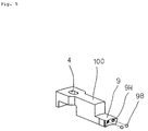
- Fig. 5 shows the other example of a stopper 100.
- This stopper 100 is equivalent with two small-hole 9H at the apical surface of the wedge part 9 of a flea tooth shape.
- a small steel-ball 9B is embedded via the grease for lubrication in the small-hole 9H, respectively. In this way, as the wedge part 9 is in contact with the cone part 8 of the revolving shaft 19 via the steel-ball 9B, the wedge part 9 is not abraded out.
- the discharge apparatus by this invention can also perform a regulation of the coin thickness extremely simply and can easily exchange the discs for discharging a coin by one-touch.
- a thick large disc is the main disc 51 which forms the principle part of the discharge apparatus for discharging the disc body in accordance with this invention.
- the main disc 51 is made with a sintered metal or a die-cast.
- the main disc 51 is inserted in the upper-end part of a rotating shaft 53 via a cylinder part 52 formed in the central part and is fixed.
- the rotating shaft 53 is rotated counterclockwise (Fig. 6) by means of a drive unit comprising an electric motor and a gear apparatus (not illustrated).
- the main disc 51 is equipped in a peripheral direction with four fairly large through-holes 54 at equal intervals.
- the circumference part of the under-surface of the main disc 51 is equipped in a peripheral direction with four triangular type fairly large hollows 55 at equal intervals. Therefore, four long and slender cutoff notches formed on the long-side part of the triangle of a hollow 55 are formed on the circumference of the main disc 51.
- the top part of the hollow 55 formed against a cutoff notch is connected to a through-hole 54.
- the long and slender arm 56 is formed between adjacent hollows.
- the long and slender arm 56 is cut. Therefore, when the main disc 51 rotates it is prevented that a guide pin (not shown) and the long and slender arm 56 are in contact.
- Some small hole 57 is formed on the circumference part of the upper surface of the main disc 51.
- a small hole 57 embeds a forceful magnet 58 made from a rare earth metal.
- a thin large disc is the iron cover disc 61 which forms the principal part of the discharge apparatus for the disc bodies in accordance with this invention.
- the cover disc 61 is equipped with an open hole 62 at its central part.
- An open hole 62 penetrates a cylinder part 52.
- the cover disc 61 is in a peripheral direction equipped with four fairly large penetration tubes 64 at equal intervals.
- the penetration tube 64 is formed downward.
- the diameter and the depth of the penetration tube 64 are decided out (or selected) in consideration of the size of the disc body for which a discharge is desired.
- the circumference part of the cover disc 61 comprises some protrusion 67.
- the protrusion 67 faces downward.
- the protrusion 67 is put in a small hole 57.
- stir pin 69 is used in place of the protrusion 67 suitably.
- the stir pin 69 is made from iron.
- the cover disc 61 can also be molded by resin.
- the cover disc 61 is put on the main disc 51. And, they are integrated as shown in Fig. 7. That is, the open hole 62 of the cover disc 61 is inserted in the cylinder part 52 of the main disc 51. Moreover, the protrusion 67 is put in the small hole 57. The protrusion 67 is fixed to the cylinder part 52 by means of the magnet 58.
- Fig. 9 shows the enlarged principal part of the other example of this invention.
- the circumference part of a main disc 91 forms a plurality of screw holes 97.
- the circumference part of a cover disc 101 forms a plurality of small holes 107.
- the cover disc 101 is put on the main disc 91. They are integrated as shown in Fig. 8. That is, the open hole 62 of the cover disc 101 is inserted in the cylinder part 52 of the main disc 91. And, bis-screw 109 is penetrated in a small hole 107 and is fixed to the screw hole 97. In this case, the head part 110 of the bis-screw 109 is used in place of the stir pin 69.
- the main disc of a piece is provided. Furthermore, a plurality of cover discs corresponding to various coins is provided. Therefore, the discharge apparatus for the disc bodies which can change size of a discharge hole simply by only choosing a cover disc depending on the size of the disc body discharged according to this invention is obtained. In other words, the discharge apparatus for the disc bodies which can change size of a discharge hole simply depending on the size of the disc body discharged according to this invention is obtained. Especially, the discharge apparatus for the disc bodies according to this invention can exchange the disc for a discharge simply depending on the size of the required coin.
Landscapes
- Physics & Mathematics (AREA)
- General Physics & Mathematics (AREA)
- Control Of Vending Devices And Auxiliary Devices For Vending Devices (AREA)
- Pinball Game Machines (AREA)
- Testing Of Coins (AREA)
- Mixers Of The Rotary Stirring Type (AREA)
- Combined Means For Separation Of Solids (AREA)
Priority Applications (1)
| Application Number | Priority Date | Filing Date | Title |
|---|---|---|---|
| EP99116417A EP0962897B1 (fr) | 1997-09-12 | 1998-09-08 | Dispositif distributeur de disques |
Applications Claiming Priority (9)
| Application Number | Priority Date | Filing Date | Title |
|---|---|---|---|
| JP28754197 | 1997-09-12 | ||
| JP287541/97 | 1997-09-12 | ||
| JP28754197A JP3516008B2 (ja) | 1997-09-12 | 1997-09-12 | 円板体放出装置 |
| JP291470/97 | 1997-09-18 | ||
| JP29147097 | 1997-09-18 | ||
| JP29147097A JP3561743B2 (ja) | 1997-09-18 | 1997-09-18 | 円板体放出装置 |
| JP37000597 | 1997-12-19 | ||
| JP370005/97 | 1997-12-19 | ||
| JP37000597A JP3687022B2 (ja) | 1997-12-19 | 1997-12-19 | サイズ変更が可能な円板体放出装置 |
Related Child Applications (1)
| Application Number | Title | Priority Date | Filing Date |
|---|---|---|---|
| EP99116417A Division EP0962897B1 (fr) | 1997-09-12 | 1998-09-08 | Dispositif distributeur de disques |
Publications (3)
| Publication Number | Publication Date |
|---|---|
| EP0903702A2 true EP0903702A2 (fr) | 1999-03-24 |
| EP0903702A3 EP0903702A3 (fr) | 1999-04-28 |
| EP0903702B1 EP0903702B1 (fr) | 2001-08-16 |
Family
ID=27337361
Family Applications (2)
| Application Number | Title | Priority Date | Filing Date |
|---|---|---|---|
| EP98116979A Expired - Lifetime EP0903702B1 (fr) | 1997-09-12 | 1998-09-08 | Distributeur de disques |
| EP99116417A Expired - Lifetime EP0962897B1 (fr) | 1997-09-12 | 1998-09-08 | Dispositif distributeur de disques |
Family Applications After (1)
| Application Number | Title | Priority Date | Filing Date |
|---|---|---|---|
| EP99116417A Expired - Lifetime EP0962897B1 (fr) | 1997-09-12 | 1998-09-08 | Dispositif distributeur de disques |
Country Status (5)
| Country | Link |
|---|---|
| US (1) | US6099402A (fr) |
| EP (2) | EP0903702B1 (fr) |
| KR (1) | KR100490473B1 (fr) |
| DE (2) | DE69800732T2 (fr) |
| ES (1) | ES2162693T3 (fr) |
Cited By (5)
| Publication number | Priority date | Publication date | Assignee | Title |
|---|---|---|---|---|
| EP1146488A2 (fr) | 2000-04-12 | 2001-10-17 | Mars Incorporated | Distributeur de pièces de monnaie et mechanisme distributeur |
| EP0959437A3 (fr) * | 1998-05-21 | 2002-04-17 | Asahi Seiko Co. Ltd. | Dispositif pour distribuer des pièces de monnaie |
| AU758528B2 (en) * | 1999-06-25 | 2003-03-27 | Asahi Seiko Kabushiki Kaisha | A coin dispensing apparatus |
| EP1557798A3 (fr) * | 2004-01-26 | 2005-08-31 | Asahi Seiko Kabushiki Kaisha | Dispositif pour distribuer des pièces de monnaie |
| EP3142081B1 (fr) * | 2015-09-09 | 2020-08-05 | Asahi Seiko Co. Ltd. | Distributeur automatique de monnaie |
Families Citing this family (9)
| Publication number | Priority date | Publication date | Assignee | Title |
|---|---|---|---|---|
| JP4047610B2 (ja) * | 2001-05-02 | 2008-02-13 | Kpe株式会社 | メダル払出装置およびメダル払出装置用メダル落とし込み機構 |
| KR100521727B1 (ko) * | 2002-03-13 | 2005-10-17 | 서광석 | 금전수납 및 지급 장치 |
| JP4499373B2 (ja) * | 2003-05-09 | 2010-07-07 | グローリー株式会社 | コインホッパ |
| US20050224313A1 (en) * | 2004-01-26 | 2005-10-13 | Cubic Corporation | Robust noncontact media processor |
| JP4784805B2 (ja) * | 2004-03-31 | 2011-10-05 | 旭精工株式会社 | コインホッパの回転ディスク |
| GB2431151A (en) * | 2005-10-14 | 2007-04-18 | Money Controls Ltd | Coin dispensing apparatus |
| CN102001491A (zh) * | 2010-12-28 | 2011-04-06 | 李�杰 | 中成药丸定量取用盒 |
| US9836909B2 (en) * | 2016-04-06 | 2017-12-05 | Shuffle Master Gmbh & Co Kg | Chip sorting devices and related assemblies, components and methods |
| US10096192B1 (en) | 2017-08-30 | 2018-10-09 | Shuffle Master Gmbh & Co Kg | Chip sorting devices and related assemblies and methods |
Family Cites Families (7)
| Publication number | Priority date | Publication date | Assignee | Title |
|---|---|---|---|---|
| US2959324A (en) * | 1959-01-21 | 1960-11-08 | Rochester Button Co | Orienter for articles in a hopper |
| AU5171885A (en) * | 1986-01-25 | 1987-07-02 | Uzihara, H. | Coin delivery |
| DE3624346A1 (de) * | 1986-07-16 | 1988-01-21 | Zu Altenschildesche Volk Meyer | Vorrichtung zum sortieren von muenzen |
| AU4066389A (en) * | 1988-08-18 | 1990-03-23 | Jack D. Dass | Coin storage and dispensing apparatus |
| JPH06119521A (ja) * | 1991-10-14 | 1994-04-28 | Kazumi Chiba | コイン払出装置 |
| US5711704A (en) * | 1993-08-12 | 1998-01-27 | Aristocrat Leisure Industries Pty. Ltd. | Coin storage and dispensing apparatus |
| JP3792766B2 (ja) * | 1996-01-30 | 2006-07-05 | アルゼ株式会社 | 遊技機用コイン払出装置 |
-
1998
- 1998-09-08 EP EP98116979A patent/EP0903702B1/fr not_active Expired - Lifetime
- 1998-09-08 ES ES98116979T patent/ES2162693T3/es not_active Expired - Lifetime
- 1998-09-08 DE DE69800732T patent/DE69800732T2/de not_active Expired - Lifetime
- 1998-09-08 EP EP99116417A patent/EP0962897B1/fr not_active Expired - Lifetime
- 1998-09-08 DE DE69801352T patent/DE69801352T2/de not_active Expired - Lifetime
- 1998-09-11 KR KR10-1998-0037532A patent/KR100490473B1/ko not_active Expired - Lifetime
- 1998-09-11 US US09/151,531 patent/US6099402A/en not_active Expired - Lifetime
Cited By (7)
| Publication number | Priority date | Publication date | Assignee | Title |
|---|---|---|---|---|
| EP0959437A3 (fr) * | 1998-05-21 | 2002-04-17 | Asahi Seiko Co. Ltd. | Dispositif pour distribuer des pièces de monnaie |
| AU758528B2 (en) * | 1999-06-25 | 2003-03-27 | Asahi Seiko Kabushiki Kaisha | A coin dispensing apparatus |
| EP1146488A2 (fr) | 2000-04-12 | 2001-10-17 | Mars Incorporated | Distributeur de pièces de monnaie et mechanisme distributeur |
| US6564965B2 (en) | 2000-04-12 | 2003-05-20 | Mars, Incorporated | Coin dispenser and dispensing mechanism |
| EP1146488A3 (fr) * | 2000-04-12 | 2004-01-21 | Mars Incorporated | Distributeur de pièces de monnaie et mechanisme distributeur |
| EP1557798A3 (fr) * | 2004-01-26 | 2005-08-31 | Asahi Seiko Kabushiki Kaisha | Dispositif pour distribuer des pièces de monnaie |
| EP3142081B1 (fr) * | 2015-09-09 | 2020-08-05 | Asahi Seiko Co. Ltd. | Distributeur automatique de monnaie |
Also Published As
| Publication number | Publication date |
|---|---|
| KR19990029724A (ko) | 1999-04-26 |
| EP0903702B1 (fr) | 2001-08-16 |
| DE69801352T2 (de) | 2002-05-16 |
| DE69800732D1 (de) | 2001-05-31 |
| ES2162693T3 (es) | 2002-01-01 |
| KR100490473B1 (ko) | 2005-08-05 |
| EP0962897B1 (fr) | 2001-04-25 |
| EP0962897A1 (fr) | 1999-12-08 |
| US6099402A (en) | 2000-08-08 |
| EP0903702A3 (fr) | 1999-04-28 |
| DE69800732T2 (de) | 2001-09-13 |
| DE69801352D1 (de) | 2001-09-20 |
Similar Documents
| Publication | Publication Date | Title |
|---|---|---|
| EP0903702A2 (fr) | Distributeur de disques | |
| DE69619596T2 (de) | Dosier- und Abgabeeinrichtung für feste Gegenstände | |
| KR100632201B1 (ko) | 고속 주화 분배 장치 | |
| WO1996005482A1 (fr) | Instrument d'affichage | |
| DE69622104T2 (de) | Spielautomat | |
| US5702101A (en) | Handheld gaming ball display device | |
| KR19990087901A (ko) | 사이즈변경가능한코인호퍼장치 | |
| US5463509A (en) | Disc cartridge holder having a shutter control arm disposed in a key-hole shaped aperture formed in the cartridge holder | |
| DE3444148C2 (de) | Geldspielautomat mit wenigstens zwei aus Gewinnanzeige-Elementen zusammengefügten Risikoleitern | |
| US6564965B2 (en) | Coin dispenser and dispensing mechanism | |
| DE69020960T2 (de) | Plattenladegerät. | |
| JP4604157B2 (ja) | 円板体の放出装置 | |
| EP1434208A2 (fr) | Structure de fixation pour bases de montage et appareil de disque muni de cette structure | |
| US20060247023A1 (en) | Symbol displaying unit for game machines | |
| JP3561743B2 (ja) | 円板体放出装置 | |
| US4580697A (en) | Cup drop ring for drink machine | |
| JP3680180B2 (ja) | パチンコ機の中央入賞装置 | |
| GB2369229A (en) | Compact coin hopper | |
| JP4002962B2 (ja) | サイズ変更可能なコインホッパ装置 | |
| JPH11185094A (ja) | サイズ変更が可能な円板体放出装置 | |
| JPH0543815Y2 (fr) | ||
| EP0594816A1 (fr) | Dispositif de maintien et d'entrainement pour des supports de substrat a mouvement planetaire. | |
| JP2000140255A (ja) | 弾球遊技機の入賞装置 | |
| CN219251617U (zh) | 用于游戏机公共转盘的挖板结构 | |
| JPH11169508A (ja) | スロットマシン |
Legal Events
| Date | Code | Title | Description |
|---|---|---|---|
| PUAI | Public reference made under article 153(3) epc to a published international application that has entered the european phase |
Free format text: ORIGINAL CODE: 0009012 |
|
| PUAL | Search report despatched |
Free format text: ORIGINAL CODE: 0009013 |
|
| AK | Designated contracting states |
Kind code of ref document: A2 Designated state(s): DE ES GB NL |
|
| AX | Request for extension of the european patent |
Free format text: AL;LT;LV;MK;RO;SI |
|
| AK | Designated contracting states |
Kind code of ref document: A3 Designated state(s): AT BE CH CY DE DK ES FI FR GB GR IE IT LI LU MC NL PT SE |
|
| AX | Request for extension of the european patent |
Free format text: AL;LT;LV;MK;RO;SI |
|
| 17P | Request for examination filed |
Effective date: 19990519 |
|
| 17Q | First examination report despatched |
Effective date: 19990729 |
|
| AKX | Designation fees paid |
Free format text: DE ES GB NL |
|
| GRAG | Despatch of communication of intention to grant |
Free format text: ORIGINAL CODE: EPIDOS AGRA |
|
| GRAH | Despatch of communication of intention to grant a patent |
Free format text: ORIGINAL CODE: EPIDOS IGRA |
|
| GRAG | Despatch of communication of intention to grant |
Free format text: ORIGINAL CODE: EPIDOS AGRA |
|
| GRAH | Despatch of communication of intention to grant a patent |
Free format text: ORIGINAL CODE: EPIDOS IGRA |
|
| GRAA | (expected) grant |
Free format text: ORIGINAL CODE: 0009210 |
|
| AK | Designated contracting states |
Kind code of ref document: B1 Designated state(s): DE ES GB NL |
|
| REF | Corresponds to: |
Ref document number: 69801352 Country of ref document: DE Date of ref document: 20010920 |
|
| REG | Reference to a national code |
Ref country code: GB Ref legal event code: IF02 Ref country code: ES Ref legal event code: FG2A Ref document number: 2162693 Country of ref document: ES Kind code of ref document: T3 |
|
| PLBE | No opposition filed within time limit |
Free format text: ORIGINAL CODE: 0009261 |
|
| STAA | Information on the status of an ep patent application or granted ep patent |
Free format text: STATUS: NO OPPOSITION FILED WITHIN TIME LIMIT |
|
| 26N | No opposition filed | ||
| PGFP | Annual fee paid to national office [announced via postgrant information from national office to epo] |
Ref country code: NL Payment date: 20160810 Year of fee payment: 19 |
|
| PGFP | Annual fee paid to national office [announced via postgrant information from national office to epo] |
Ref country code: GB Payment date: 20160907 Year of fee payment: 19 Ref country code: DE Payment date: 20160831 Year of fee payment: 19 |
|
| PGFP | Annual fee paid to national office [announced via postgrant information from national office to epo] |
Ref country code: ES Payment date: 20160810 Year of fee payment: 19 |
|
| REG | Reference to a national code |
Ref country code: DE Ref legal event code: R119 Ref document number: 69801352 Country of ref document: DE |
|
| REG | Reference to a national code |
Ref country code: NL Ref legal event code: MM Effective date: 20171001 |
|
| GBPC | Gb: european patent ceased through non-payment of renewal fee |
Effective date: 20170908 |
|
| PG25 | Lapsed in a contracting state [announced via postgrant information from national office to epo] |
Ref country code: NL Free format text: LAPSE BECAUSE OF NON-PAYMENT OF DUE FEES Effective date: 20171001 |
|
| PG25 | Lapsed in a contracting state [announced via postgrant information from national office to epo] |
Ref country code: GB Free format text: LAPSE BECAUSE OF NON-PAYMENT OF DUE FEES Effective date: 20170908 Ref country code: DE Free format text: LAPSE BECAUSE OF NON-PAYMENT OF DUE FEES Effective date: 20180404 |
|
| REG | Reference to a national code |
Ref country code: ES Ref legal event code: FD2A Effective date: 20181019 |
|
| PG25 | Lapsed in a contracting state [announced via postgrant information from national office to epo] |
Ref country code: ES Free format text: LAPSE BECAUSE OF NON-PAYMENT OF DUE FEES Effective date: 20170909 |