EP0903829A1 - Dispositif de filtrage comportant un circuit de controle et appareil électrique comportant un tel dispositif - Google Patents
Dispositif de filtrage comportant un circuit de controle et appareil électrique comportant un tel dispositif Download PDFInfo
- Publication number
- EP0903829A1 EP0903829A1 EP98410088A EP98410088A EP0903829A1 EP 0903829 A1 EP0903829 A1 EP 0903829A1 EP 98410088 A EP98410088 A EP 98410088A EP 98410088 A EP98410088 A EP 98410088A EP 0903829 A1 EP0903829 A1 EP 0903829A1
- Authority
- EP
- European Patent Office
- Prior art keywords
- filtering
- current
- line
- signal
- control
- Prior art date
- Legal status (The legal status is an assumption and is not a legal conclusion. Google has not performed a legal analysis and makes no representation as to the accuracy of the status listed.)
- Granted
Links
Images


Classifications
-
- H—ELECTRICITY
- H02—GENERATION; CONVERSION OR DISTRIBUTION OF ELECTRIC POWER
- H02J—ELECTRIC POWER NETWORKS; CIRCUIT ARRANGEMENTS OR SYSTEMS FOR SUPPLYING OR DISTRIBUTING ELECTRIC POWER; SYSTEMS FOR STORING ELECTRIC ENERGY
- H02J3/00—Circuit arrangements for AC mains or AC distribution networks
- H02J3/01—Arrangements for reducing harmonics or ripples
-
- Y—GENERAL TAGGING OF NEW TECHNOLOGICAL DEVELOPMENTS; GENERAL TAGGING OF CROSS-SECTIONAL TECHNOLOGIES SPANNING OVER SEVERAL SECTIONS OF THE IPC; TECHNICAL SUBJECTS COVERED BY FORMER USPC CROSS-REFERENCE ART COLLECTIONS [XRACs] AND DIGESTS
- Y02—TECHNOLOGIES OR APPLICATIONS FOR MITIGATION OR ADAPTATION AGAINST CLIMATE CHANGE
- Y02E—REDUCTION OF GREENHOUSE GAS [GHG] EMISSIONS, RELATED TO ENERGY GENERATION, TRANSMISSION OR DISTRIBUTION
- Y02E40/00—Technologies for an efficient electrical power generation, transmission or distribution
- Y02E40/40—Arrangements for reducing harmonics
Definitions
- the invention relates to a filtering device according to the preamble of claim 1 as well an electrical appliance comprising at least one such device.
- Filtering devices are used to eliminate or attenuate currents or voltages harmonics in electrical distribution networks. Harmonic currents are caused by non-linear loads connected to the distribution networks. The charges the most common disturbances are switching power supplies, converters or regulators with electronic power components.
- the filtering devices generally comprise passive filters and active filters.
- the passive filters work like current sinks and absorb harmonics from frequencies substantially equal to the resonance frequencies of said filters.
- Active filters allow to restore a sinusoidal current in the network by compensating the currents deformed by non-linear loads. The compensation is done by injecting a current of correction in parallel in the network. The network current then corresponds to the sum of the distorted load current and correction current.
- Passive filters generally include filter cells each comprising a inductor in series with a capacitor. Each filter cell is assigned to one harmonic frequency of the disturbing currents. To be effective, these filters must be perfectly tuned to said harmonic frequency. But it is very difficult to get high precision passive components for high powers. Moreover, the characteristics of the components may change as they age or when the temperature usage varies. Another difficulty linked to the use of passive filters concerns their implementation. parallel. Indeed, the association of several passive filtering cells creates interactions between cells and changes the tuning frequencies of said cells. Likewise, the connection on reactive power compensation capacitor lines creates disturbances in filtering devices by modifying the tuning frequencies. Passive band filters can also lose their effectiveness if the fundamental frequency of the network varies, even in small proportions.
- Active filters are less sensitive to variations in the configuration of an installation electric since they generally have slave control devices.
- the active filters are limited in power because of the electronic components they contain. Indeed, electronic components of linear power, such as transistors, are limited in voltage and current.
- the object of the invention is a filtering device that is not very sensitive to variations in the impedance of a network and component value drifts.
- the resonance frequency of the at least one passive filter cell is greater than at least one predetermined harmonic frequency.
- the switching means are controlled in closing by signals of pulses and in opening by a zero crossing of a filtering current which crosses them.
- the switching means comprise two thyristors connected head to tail.
- the first and second pulse signals are substantially in opposition to phase.
- control means include pulse generating means providing the first and second pulse signals and synchronization means connected to the network line and to said generating means for synchronizing the signals of pulses with a signal representative of the line voltage of the network.
- control means include means for modulating the phase between the first and second pulse signals as a function of a signal representative of the voltage of said at least one network line.
- control means include means for processing of signals connected to the first means of measuring electrical magnitude of line to extract a signal representative of said at least one harmonic frequency of said line electrical magnitude signal.
- the filtering device comprises second current measurement means connected to the signal processing means to provide a signal representative of a filtering current flowing in at least one filtering cell, said processing means of signals comparing the signal representative of a filtering current and the signal representative of said at least one harmonic frequency of the line electrical quantity signal.
- the signal processing means determine a difference in amplitude between the signal representative of said at least one harmonic frequency of the electrical quantity signal of line and the signal representative of a filtering current to control the control of the means switching so as to reduce said at least difference in amplitude.
- the signal processing means determine a phase shift between the signal representative of said at least one harmonic frequency of the line electrical quantity signal and the signal representative of a filtering current for controlling the switching means so to reduce said phase shift.
- the filter device includes an inductor arranged in parallel on the switching means.
- the filtering device comprises several cells of passive filtering tuned to different frequencies and each controlled by means different switching means, the control means controlling each means of switching according to different harmonic frequencies.
- the first means of measuring electrical line quantity include current measurement means arranged on said network line between a disturbing electrical charge and a filter cell.
- the first means of measuring electrical line quantity comprise current measuring means arranged on said at least one network line between a source of electrical energy and said at least one filtering cell.
- the first means of measuring electrical magnitude comprise voltage measurement means connected to said at least one network line.
- the filtering device may include means for active filtering connected to a line of the electrical network, a common control device connected to said switching means and to active filtering means, and means for measurement providing a signal representative of a total filtering current, said device for common control comprising the control means connected to the switching means.
- An electrical appliance comprises at least one filtering device according to the invention such as defined above.
- the electrical appliance can also include an active filtering device.
- the electrical appliance includes a common control device for controlling the active filtering device and the switching means.
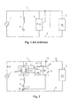
- Electrical installations like that shown in Figure 1 generally include at least one source 1 of electrical energy and at least one electrical charge 2 connected by lines 3 and 4.
- currents disturbers circulate in connection lines 3 and 4.
- filtering devices are connected to said lines 3 and 4.
- a filtering can include, as in FIG. 1, a passive filtering cell comprising a inductor 5 and a capacitor 6 connected in series. These elements form a resonant circuit which absorbs currents whose frequency is substantially equal to that of the frequency of resonance.
- Active filters can also be used to mitigate the effects disturbances of current or voltage harmonics. Active filters connected to lines 3 and 4 inject or absorb currents to compensate for the deformations of the line currents or voltages.
- Passive filters must have high precision components to be able to absorb current harmonics effectively. This precision is very difficult to obtain because it requires precise adjustment. In addition, the characteristics of components vary over time and depending on the temperature.
- a filtering device comprises at least one passive filter cell connected in series with an electronic switching device to control a current flowing in said passive filter cell. So the precision of the filtering no longer depends on the accuracy of the cell but on a device control circuit of commutation.
- a device according to the invention can adapt to variations in impedance and network frequency. It is possible to operate a device according to the invention at different network frequencies, for example at 50Hz and 60Hz, without modifying the filtering.
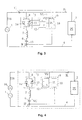
- a first embodiment is shown in Figure 2. It includes a cell passive filtering composed of an inductor 5 and a capacitor 6, and a switch electronics 8 connected in series with said filter cell. Switch 8 is controlled by a control circuit 9 which supplies control signals as a function of electrical signals measured on at least one line of the network.
- the control circuit 9 comprises a signal processing circuit 10 connected, in particular to a current sensor 11 providing a signal representative of a circulating line current IL in the disruptive load 2.
- the processing circuit 10 determines the characteristics of a harmonic current to be attenuated and provides a control signal to a signal generator 12 control.
- the device of FIG. 2 includes a current sensor 13 arranged in series with the passive filtering cell to supply the circuit processing 10 a signal representative of a filtering current IF.
- the processing circuit extract from the line current signal IL a value representative of the harmonic to be attenuated HIL and compares it to the signal representative of the IF filtering current.
- circuit 10 controls the generator 12 so that the filtering current is in phase opposition and same amplitude compared to the harmonic signal.
- the control circuit 9 operates on a servo loop in order to restore current IS source correct.
- the processing circuit 10 and the generator 12 receive a signal representative of a line voltage VL to synchronize the determination of values representative of the phase of the harmonics to be attenuated HIL and the supply of the switch control 8.
- the electronic switch 8 includes electronic components for power controlled in closing by pulses and opening during a zero crossing of the current flowing through them. These components are advantageously thyristors which allow the switching of high currents and withstand high voltages. So in a mode of preferred embodiment, the switch 8 comprises two thyristors 14 and 15 connected head to tail in series with the passive filter cell. A first thyristor 14 conducts the alternation positive and a second thyristor 15 conducts the negative alternation of the filtering current IF. control thyristors 14 and 15, generator 12 provides control pulses to triggers of said thyristors.
- switch 8 is controlled at a medium frequency substantially equal to the frequency of the HIL harmonic to be attenuated.
- the pulse signals supplied by the generator 12 to each thyristor are substantially in phase opposition or offset by half a period.
- FIG. 3 shows a second embodiment in which the current sensor 11 is arranged on a line 3 between the source 1 and the passive filtering cell 5 and 6 in series with the switch 8.
- the current sensor 11 measures the source current IS and the control circuit controls switch to eliminate or attenuate currents disturbing harmonics generated by load 2 and which could propagate on the current source.
- the processing circuit 10 extracts from the source current IS a representative signal of an HIS current harmonic to be eliminated and controls the generator 12 to reduce said HIS signal.
- the circuit 9 controls the switch 8 to adapt the IF filtering current and reduce the HIS signal.
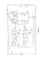
- Figure 4 shows a third embodiment in which the electrical line quantity measured is a voltage VL of line 3.
- the processing circuit 10 extract from a measured voltage signal VL a signal representative of a voltage harmonic HVL to eliminate or mitigate.
- a harmonic voltage is representative of a current harmonic flowing in an impedance.
- the harmonic voltage is represented by a harmonic voltage generator 16 arranged in series with the source electrical energy 1.
- the filtering device can eliminate produced harmonics by the load 2 as in the two previous embodiments represented on the Figures 2 and 3 but also disturbing harmonics that can come from the network.
- the device of figure 4 attenuates the disturbances generated by the non-linear behavior of the load 2 and protects said load against disturbances produced by other network loads.
- control circuit 9 controls switch 8 to modify the IF current and decrease the HVL signal.
- FIGS. 5a to 5d show signals of a filtering device according to a mode of embodiment of the invention making it possible to eliminate or attenuate a harmonic current of rank five.
- Pulse signals 17 and 18 supplied by generator 12 to control the two thyristors 14 and 15 are shown respectively in FIGS. 5a and 5b.
- On the face 5c are shown a curve representative of a line voltage VL and a curve representative of a voltage VC of the capacitor 6.
- the filtering current IF is represented by a curve in Figure 5d.
- a signal pulse 17 controls the conduction of the thyristor 14.
- the voltage VL being greater than the voltage VC
- an IF current flows in the passive filter cell.
- the shape of the current has the shape of a half-sinusoid whose period depends essentially on the values of the capacitor 6 and of inductance 5.
- the current IF induced by inductance 5 charges capacitor 6 to a voltage VC greater than VL then this current is canceled on zero crossing and the thyristor 14 stops lead to time t2.
- a pulse of the signal 18 controls the conduction of the thyristor 15.
- the voltage VC being higher than voltage VL, a current IF of reverse polarity flows in the passive filter cell 5 and 6 then stops at an instant t4 before the appearance of a next signal pulse 17.
- the frequency of the pulses of each signal 17 or 18 is substantially equal to the frequency of the harmonic to be attenuated and signals 17 and 18 are shifted substantially by half a period corresponding to the frequency of said harmonic to be attenuated.
- the current in the filter cell through a thyristor is interrupted before another pulse controls the conduction of the other thyristor. Therefore, the frequency of resonance of the passive filter cell 5 and 6 is preferably greater than the frequency of pulses of each signal 14 or 15 and higher than the frequency of the harmonic to be attenuated.
- each sinusoid lobe corresponding to a half period is ends before the start of the next conduction and the corresponding thyristors are blocked automatically.
- a filtering device may include a smoothing inductor 19 connected at branch or in parallel on switch 8.
- Figure 7 illustrates a representative curve of a filtering current IF of a device according to FIG. 6.
- the filtering current IF has, in this case, a more continuous variation in two half-waves of opposite polarities.
- Figures 8a to 8c illustrate representative curves of currents flowing in a circuit electric comprising a filtering device according to the invention.
- Figure 8a shows a IL current flowing in a disturbing load 2.
- Figure 8b shows a current of IF filtering intended to compensate for disturbances generated by the load current at a predetermined harmonic frequency.
- Figure 8c shows a filtered source current corresponding to the sum of the line current IL and the filtering current IF.
- the current IL of FIG. 8a has, in this embodiment, a fundamental frequency of 50Hz corresponding to the frequency of the electrical voltage source 1.
- the load 2 including a rectifier, generates on line 3 a harmonic disturbance five with respect to the fundamental frequency.
- This disturbed current IL shown in FIG. 8a has flat parts 20 where the current is zero and sinusoid peaks disturbed by current dips 21.
- the processing circuit 10 analyzes the current of FIG. 8a and extracts the amplitude and the phase of the disturbing current harmonic five. Then the control signal generator sends pulses to switch 8 to generate an IF filter current. This current of filtering represented on figure 8b compares the current of the disturbing harmonic five.
- the filtering current IF restores a substantially sinusoidal source current IS represented in Figure 8c.
- the harmonic disturbances five generated by the charge are not not spread through the electrical distribution network.
- Curves representing the spectral analysis as a function of the frequency of the charging currents IL and IS source are shown respectively in Figures 9a and 9b.
- the current IL has a fundamental F and a harmonic five H5 of high amplitudes as well as other harmonics, including harmonics seven H7, eleven H11 and thirteen H13.
- the filtering device attenuates the harmonic currents five H5, therefore, said harmonic H5 is no longer present in the frequency spectrum of the current IS of figure 9b.
- the fundamental frequency current F and the other harmonics H7, H11 and 13 are found on the source current IS.
- a device can have several passive filter cells controlled by switches and a circuit 9.
- a filtering device may include a cell to attenuate the five H5 harmonics and a cell to attenuate the seven H7 harmonics which are the most elevated in the spectral analysis of Figure 9a.
- FIG. 10 An embodiment of a filtering device making it possible to attenuate or eliminate two harmonics is shown in Figure 10.
- This device comprises a first cell comprising an inductor 5a and a capacitor 6a in series with a switch 8a for compensate a first harmonic current and a second cell comprising an inductance 5b and a capacitor 6b in series with a switch 8b to compensate for a second current harmonic.
- the control device 9 comprises a first processing circuit 10a and a first generator 12a for controlling the switch 8a and a second processing circuit 10b and a second generator 12a for controlling the switch 8b.
- a first filtering current IF1 having a first frequency to compensate for a first harmonic, crosses the first cell 5a-6a
- a second IF2 filtering current having a second frequency to compensate for a second harmonic
- the IF filter current is then the sum of two currents IF1 and IF2 of different frequencies.
- Each processing circuit 10a and 10b receives signals representative of the line current IL, the filtering current IF and the line voltage VL.
- the first circuit 10a extracts current signals that it receives signals representative of a first harmonic frequency. These signals are applied to the input of a first control module 22d of the phase of the first filtering current IF1 having the first harmonic frequency.
- a first module of amplitude control 23a receives the signals extracted by the first processing circuit 10a. This circuit controls the amplitude of the first filter current IF1. This amplitude can advantageously be modulated as a function of the voltage VL of line 3. For this, the circuit 23a receives a signal representative of the line voltage VL.
- the phase and amplitude control modules 22a and 23a control the first generator 12a.
- the generator 12a supplies control pulses as a function of the amplitude and of the phase of the signals having the first harmonic frequency.
- the pulse signals 17 and 18 supplied by generator 12a can be synchronized with the line voltage VL.
- a first synchronization module 24a is disposed between the line voltage VL and generator 12a.
- the second filter current IF2 is checked in the same way as the first.
- the second processing circuit 10b extracts current signals which it receives, signals representative of a second harmonic frequency.
- a second phase control module 22b and a second amplitude control module 23b are disposed between the circuit processing 10b and the generator 12b.
- the synchronization of the pulses supplied by the generator 12b is provided by a second synchronization module 24b.
- Figures 11a to 11d show signals from a filter device including a control the amplitude of the IF filtering current. To control said amplitude, the signals of pulses 17 and 18 are no longer exactly in phase opposition but can be shifted early or late from a middle position.
- Figure 1 shows a first reference pulse 17 and a second pulse 17 ahead of its normal position.
- FIG. 11b shows a pulse 18 late with respect to its position normal median.
- Figure 11c shows the line voltage VL and the capacitor voltage VC according to normal pulses (curves 26) or modulated (curve 27).
- Figure 11d shows the IF current amplitude controlled. In this figure, the current IF has an amplitude reduced (curve 28) compared to an initial curve 29 without modulation.
- pulse generators 12, 12a or 12b can also supply pulses as a function of the voltage VC of capacitors 6, 6a or 6b of filter cells.
- the filtering devices according to the invention can be used with active filters. In this case, for example, filtering devices according to an embodiment of the invention attenuate high power disturbances and an active filter attenuates other harmonic disturbances of different frequencies. Therefore, active filtering may be of low power.
- an active filter comprising an electronic power circuit 33 is connected to lines 3 and 4 feed.
- the control of the circuit 33 is ensured by a regulation circuit 32 connected to said circuit 33, to a current sensor 30 providing a signal representative of the current of line IL, and to a current sensor 31 providing a signal representative of a current of IFA active filtering.
- the circuit 32 can also receive a signal representative of the line voltage VL.
- active filters can be integrated into filtering devices according to the invention.
- a diagram of an embodiment of a filtering device incorporating a filter active is shown in Figure 13.
- a control circuit 34 is connected to switch 8 and to active filter 33 to control the two types of filtering.
- the circuit 34 receives signals representative of IL line currents supplied by the sensor 11, VL line voltage, and total IFT filtering provided by a sensor 35 measuring the IFA current flowing in the active filter and the IF filter current flowing in the cell comprising the inductor 5 and the capacitor 6.
- the circuit 34 includes in particular the functions circuits 9 and 34 to process all of the signals and control all of the filtering.
- the circuits of the control devices 9 can be produced discreetly by digital or analog components or partially or fully integrated under a shape programmed in a microprocessor device.
- Devices according to embodiments of the invention can be arranged in parallel in an electrical installation. Each device being able to function to attenuate identical or different harmonics. They can also be combined with filtering different active or passive, or reactive energy compensation devices.
- filtering devices according to the invention can be connected in star or triangle.
- the switches 8 preferably comprise thyristors making it possible to switch a high electrical power with low losses but other semiconductor components of power can perfectly replace them.
Landscapes
- Engineering & Computer Science (AREA)
- Power Engineering (AREA)
- Supply And Distribution Of Alternating Current (AREA)
- Power Conversion In General (AREA)
Abstract
Description
- La figure 1 montre le schéma bloc d'une installation électrique comportant un dispositif de filtrage connu,
- Les figures 2 et 3 représentent un premier et un second schémas de dispositifs de filtrage selon des modes de réalisation de l'invention détectant des perturbations de courant,
- La figure 4 représente un schéma d'un dispositif de filtrage selon un mode de réalisation de l'invention détectant des perturbations de tension,
- Les figures 5a à 5d montrent des signaux électriques dans un dispositif selon l'invention,
- La figure 6 représente un schéma d'un dispositif de filtrage comportant une inductance de lissage,
- La figure 7 montre une courbe d'un courant de filtrage d'un dispositif selon la figure 5,
- Les figures 8a à 8c montrent des courbes de courants dans un dispositif de filtrage selon un mode de réalisation de l'invention,
- Les figures 9a et 9b montrent des harmoniques de courbes de courants selon les figures 8a et 8c,
- La figure 10 représente le schéma d'un mode de réalisation d'un dispositif de filtrage selon l'invention filtrant deux harmoniques,
- Les figures 11a à 11d montrent des courbes de courant et de tension dans un dispositif de filtrage selon un mode de réalisation de l'invention comportant des moyens de modulation du courant de filtrage,
- Les figures 12 et 13 représentent un premier et un second schémas de dispositifs de filtrage selon des modes de réalisation de l'invention associés à des filtres actifs.
Les dispositifs de filtrage selon l'invention peuvent être utilisés avec des filtres actifs. Dans ce cas, par exemple, des dispositifs de filtrage selon un mode de réalisation de l'invention atténuent des perturbations de forte puissance et un filtre actif atténue des autres perturbations harmoniques de fréquences différentes. Par conséquent, le filtrage actif peut être de faible puissance.
Claims (20)
- Dispositif de filtrage comportant :dispositif caractérisé en ce que les moyens de contrôle (9) fournissent aux moyens de commutation (8) un premier signal d'impulsions (17) pour commander la conduction des alternances positives d'un courant de filtrage (IF) et un second signal d'impulsions (18) pour commander la conduction des alternances négatives dudit courant de filtrage (IF) de manière à atténuer des courants perturbateurs ayant ladite au moins une fréquence harmonique.au moins une cellule de filtrage passif (5, 6, 5a, 6a, 5b, 6b) connectée à une ligne (3) d'un réseau électrique susceptible d'être traversée par des courants harmoniques perturbateurs,des moyens de commutation électroniques (8) connectés en série avec ladite cellule de filtrage passif, etdes moyens de contrôle (9) connectés auxdits moyens de commutation et à des premiers moyens de mesure (11) de grandeur électrique de ligne (IL, IS, VL), les moyens de contrôle commandant les moyens de commutation en fonction d'au moins une fréquence harmonique prédéterminée (H5, H7) d'un signal représentatif de la grandeur électrique de ligne fourni par les premiers moyens de mesure,
- Dispositif de filtrage selon la revendication 1, caractérisé en ce que la fréquence de résonance de ladite au moins une cellule de filtrage passif (5, 5a, 6a, 5b, 6b) est supérieure à au moins une fréquence harmonique prédéterminée (H5, H7).
- Dispositif de filtrage selon l'une des revendications 1 ou 2, caractérisé en ce que les moyens de commutation (8) sont commandés en fermeture par des signaux d'impulsions et en ouverture par un passage à zéro d'un courant de filtrage (IF) qui les traverse.
- Dispositif de filtrage selon l'une quelconque des revendications 1 à 3, caractérisé en ce que les moyens de commutation (8) comportent deux thyristors (14, 15) connectés en tête-bêche.
- Dispositif de filtrage selon l'une quelconque des revendications 1 à 4, caractérisé en ce que les premier et second signaux d'impulsions (17, 18) sont sensiblement en opposition de phase.
- Dispositif de filtrage selon l'une quelconque des revendications 1 à 5, caractérisé en ce que les moyens de contrôle comportent des moyens générateurs d'impulsions (12, 12a, 12b) fournissant les premier et second signaux d'impulsions (17, 18), et des moyens de synchronisation connectés à la ligne du réseau et auxdits moyens générateurs pour synchroniser les signaux d'impulsions avec un signal représentatif de la tension de ligne (VL) du réseau.
- Dispositif de filtrage selon l'une quelconque des revendications 1 à 6, caractérisé en ce que les moyens de contrôle comportent des moyens de modulation (23a, 23b) de la phase entre les premier et second signaux d'impulsions (17, 18) en fonction d'un signal représentatif de la tension (VL) de ladite au moins ligne (3) du réseau.
- Dispositif de filtrage selon l'une quelconque des revendications 1 à 7, caractérisé en ce que les moyens de contrôle comportent des moyens de traitement (10, 10a, 10b) de signaux connectés aux premiers moyens de mesure de grandeur électrique de ligne pour extraire un signal représentatif de ladite au moins une fréquence harmonique (H5, H7) dudit signal de grandeur électrique de ligne.
- Dispositif de filtrage selon la revendication 8, caractérisé en ce qu'il comporte des seconds moyens de mesure de courant (13) connectés aux moyens de traitement (10) de signaux pour fournir un signal représentatif d'un courant de filtrage (IF) circulant dans ladite au moins une cellule de filtrage, lesdits moyens de traitement de signaux comparant le signal représentatif d'un courant de filtrage et le signal représentatif de ladite au moins une fréquence harmonique du signal de grandeur électrique de ligne.
- Dispositif de filtrage selon la revendication 9, caractérisé en ce que les moyens de traitement de signaux (10, 10a, 10b) déterminent une différence d'amplitude entre le signal représentatif de ladite au moins une fréquence harmonique (HS, H7) du signal de grandeur électrique de ligne et le signal représentatif d'un courant de filtrage (IF) pour asservir la commande des moyens de commutation (8) de manière à réduire ladite au moins différence d'amplitude.
- Dispositif de filtrage selon l'une des revendications 9 ou 10, caractérisé en ce que les moyens de traitement de signaux déterminent un déphasage entre le signal représentatif de ladite au moins une fréquence harmonique du signal de grandeur électrique de ligne (H5, H7) et le signal représentatif d'un courant de filtrage (IF) pour commander les moyens de commutation (8) de manière à réduire ledit déphasage.
- Dispositif de filtrage selon l'une quelconque des revendications 1 à 11, caractérisé en ce qu'il comporte une inductance (19) disposée en parallèle sur les moyens de commutation (8).
- Dispositif de filtrage selon l'une quelconque des revendications 1 à 12, caractérisé en ce qu'il comporte plusieurs cellules de filtrage passif (5, 6, 6a, 5b, 6b) accordées à des fréquences différentes et commandées chacune par des moyens de commutation différents (12, 12a, 12b), les moyens de contrôle commandant chaque moyen de commutation en fonction de fréquences harmoniques différentes (H5, H7).
- Dispositif de filtrage selon l'une quelconque des revendications 1 à 13, caractérisé en ce que les premiers moyens de mesure de grandeur électrique de ligne comportent des moyens de mesure de courant (11) disposés sur ladite ligne du réseau entre une charge électrique (3) perturbatrice et au moins une cellule de filtrage (5, 6).
- Dispositif de filtrage selon l'une quelconque des revendications 1 à 13, caractérisé en ce que les premiers moyens de mesure de grandeur électrique de ligne comportent des moyens de mesure de courant (11) disposés sur ladite ligne du réseau entre une source d'énergie électrique (1) et ladite au moins une cellule de filtrage (5, 6).
- Dispositif de filtrage selon l'une quelconque des revendications 1 à 15, caractérisé en ce que les premiers moyens de mesure de grandeur électrique comportent des moyens de mesure de tension (VL) connectés à ladite au moins une ligne du réseau.
- Dispositif de filtrage selon l'une quelconque des revendications 1 à 15, caractérisé en ce qu'il comporte des moyens de filtrage actif (33) connectés à une ligne (3) d'un réseau électrique, un dispositif de contrôle commun connecté auxdits moyens de commutation et aux moyens de filtrage actif, et des moyens de mesure fournissant un signal représentatif d'un courant de filtrage total (IFT), ledit dispositif de contrôle commun comportant les moyens de contrôle connectés aux moyens de commutation.
- Appareil électrique caractérisé en ce qu'il comporte au moins un dispositif de filtrage selon l'une quelconque des revendications 1 à 17.
- Appareil électrique selon la revendication 18 caractérisé en ce qu'il comporte un dispositif de filtrage actif (30, 31, 32, 33).
- Appareil électrique selon la revendication 19 caractérisé en ce qu'il comporte un dispositif de contrôle commun (34) pour commander le dispositif de filtrage actif et les moyens de commutation (8).
Applications Claiming Priority (2)
| Application Number | Priority Date | Filing Date | Title |
|---|---|---|---|
| FR9710669A FR2767610B1 (fr) | 1997-08-21 | 1997-08-21 | Dispositif de filtrage comportant un circuit de controle et appareil electrique comportant un tel dispositif |
| FR9710669 | 1997-08-21 |
Publications (2)
| Publication Number | Publication Date |
|---|---|
| EP0903829A1 true EP0903829A1 (fr) | 1999-03-24 |
| EP0903829B1 EP0903829B1 (fr) | 2005-10-12 |
Family
ID=9510510
Family Applications (1)
| Application Number | Title | Priority Date | Filing Date |
|---|---|---|---|
| EP98410088A Expired - Lifetime EP0903829B1 (fr) | 1997-08-21 | 1998-08-06 | Dispositif de filtrage comportant un circuit de controle et appareil électrique comportant un tel dispositif |
Country Status (4)
| Country | Link |
|---|---|
| US (1) | US6140866A (fr) |
| EP (1) | EP0903829B1 (fr) |
| DE (1) | DE69831841T2 (fr) |
| FR (1) | FR2767610B1 (fr) |
Families Citing this family (12)
| Publication number | Priority date | Publication date | Assignee | Title |
|---|---|---|---|---|
| US6624684B2 (en) * | 2001-04-13 | 2003-09-23 | Applied Pulsed Power, Inc. | Compact high voltage solid state switch |
| US7078940B2 (en) * | 2004-06-02 | 2006-07-18 | Lucent Technologies Inc. | Current comb generator |
| US7095636B2 (en) * | 2004-09-15 | 2006-08-22 | Honeywell International Inc. | Electromagnetic interference filter for an autotransformer |
| DE602006008883D1 (de) * | 2005-12-30 | 2009-10-15 | St Microelectronics Sa | Schaltkreis eines Transkonduktanzfilters, insbesondere für ein Mobiltelefon |
| CN102064549B (zh) * | 2009-11-11 | 2016-03-16 | 王海 | 交流电容器投切方法及投切开关电路 |
| DE102011076877A1 (de) * | 2011-06-01 | 2012-12-06 | Siemens Aktiengesellschaft | Adaptiver Netzfilter |
| CN102214925B (zh) * | 2011-06-14 | 2013-10-02 | 徐仲周 | 中频熔炼炉滤波装置 |
| CN104969466B (zh) * | 2013-02-06 | 2018-11-23 | 三菱电机株式会社 | 滤波装置及电动车驱动控制装置 |
| US9399216B2 (en) | 2013-12-30 | 2016-07-26 | General Electric Company | Fluid transport in microfluidic applications with sensors for detecting fluid presence and pressure |
| FR3034929B1 (fr) | 2015-04-08 | 2019-03-22 | Schneider Electric Industries Sas | Systeme de filtrage actif |
| KR102499262B1 (ko) * | 2015-10-14 | 2023-02-13 | 삼성전자주식회사 | 액티브 필터 및 그 제어방법, 액티브 필터를 포함하는 전력 관리 시스템 |
| CN114362142A (zh) * | 2021-12-06 | 2022-04-15 | 国网河南省电力公司荥阳市供电公司 | 大规模风电的电力系统储能电源优化设备 |
Citations (4)
| Publication number | Priority date | Publication date | Assignee | Title |
|---|---|---|---|---|
| US4394614A (en) * | 1981-09-15 | 1983-07-19 | Westinghouse Electric Corp. | Static VAR generators |
| EP0645866A1 (fr) * | 1993-09-20 | 1995-03-29 | Asea Brown Boveri Ab | Procédé de surveillance et régulation d'un composant dans un réseau |
| US5434497A (en) * | 1993-06-02 | 1995-07-18 | General Electric Company | Vernier enhanced control for shunt connected thyristor-controlled capacitors |
| EP0742631A2 (fr) * | 1995-05-11 | 1996-11-13 | Schneider Electric Sa | Dispositif de filtrage |
Family Cites Families (10)
| Publication number | Priority date | Publication date | Assignee | Title |
|---|---|---|---|---|
| SE423771B (sv) * | 1978-07-03 | 1982-05-24 | Asea Ab | Stromriktarutrustning for overforing av energi mellan ett vexelspenningsnet och ett likspenningsnet |
| JPS6114228Y2 (fr) * | 1979-10-15 | 1986-05-02 | ||
| DE3464828D1 (en) * | 1983-02-08 | 1987-08-20 | Bbc Brown Boveri & Cie | Reactive power compensator |
| JPS63242135A (ja) * | 1987-03-27 | 1988-10-07 | 三菱電機株式会社 | 無効電力補償装置 |
| SE465596B (sv) * | 1990-02-16 | 1991-09-30 | Asea Brown Boveri | Seriekondensatorutrustning med styrbar krets foer daempning av subsynkrona resonanssvaengningar |
| SE504303C2 (sv) * | 1994-10-25 | 1996-12-23 | Asea Brown Boveri | Trefasig filterutrustning |
| US5731965A (en) * | 1996-06-21 | 1998-03-24 | Wisconsin Alumni Research Foundation | Power line harmonic reduction by hybrid parallel active/passive filter system with square wave inverter and DC bus control |
| US5910889A (en) * | 1996-11-26 | 1999-06-08 | General Electric Company | Hybrid active power filter with programmed impedance characteristics |
| US5737198A (en) * | 1996-11-26 | 1998-04-07 | General Electric Company | Hybrid active power filter with programmed impedance characteristics |
| US5844791A (en) * | 1997-06-30 | 1998-12-01 | Mte Corporation | Single-phase harmonic filter system |
-
1997
- 1997-08-21 FR FR9710669A patent/FR2767610B1/fr not_active Expired - Fee Related
-
1998
- 1998-07-24 US US09/121,589 patent/US6140866A/en not_active Expired - Lifetime
- 1998-08-06 DE DE69831841T patent/DE69831841T2/de not_active Expired - Lifetime
- 1998-08-06 EP EP98410088A patent/EP0903829B1/fr not_active Expired - Lifetime
Patent Citations (4)
| Publication number | Priority date | Publication date | Assignee | Title |
|---|---|---|---|---|
| US4394614A (en) * | 1981-09-15 | 1983-07-19 | Westinghouse Electric Corp. | Static VAR generators |
| US5434497A (en) * | 1993-06-02 | 1995-07-18 | General Electric Company | Vernier enhanced control for shunt connected thyristor-controlled capacitors |
| EP0645866A1 (fr) * | 1993-09-20 | 1995-03-29 | Asea Brown Boveri Ab | Procédé de surveillance et régulation d'un composant dans un réseau |
| EP0742631A2 (fr) * | 1995-05-11 | 1996-11-13 | Schneider Electric Sa | Dispositif de filtrage |
Also Published As
| Publication number | Publication date |
|---|---|
| EP0903829B1 (fr) | 2005-10-12 |
| US6140866A (en) | 2000-10-31 |
| DE69831841D1 (de) | 2005-11-17 |
| DE69831841T2 (de) | 2006-07-13 |
| FR2767610B1 (fr) | 1999-10-01 |
| FR2767610A1 (fr) | 1999-02-26 |
Similar Documents
| Publication | Publication Date | Title |
|---|---|---|
| EP0903829B1 (fr) | Dispositif de filtrage comportant un circuit de controle et appareil électrique comportant un tel dispositif | |
| EP0129492B1 (fr) | Méthode et système d'interconnexion de réseaux triphasés synchrones ou asynchrones au moyen d'impédances réactives variables | |
| EP0654887B1 (fr) | Alimentation sans coupure à neutre traversant, comportant un hacheur-élévateur double | |
| EP2859651B1 (fr) | Circuit d'absorption d'une ondulation de puissance et procédé associé | |
| EP0720281B1 (fr) | Dispositif électronique de conversion de l'énergie électrique | |
| FR2632130A1 (fr) | Systeme a fonctionnement parallele pour des convertisseurs delivrant un courant alternatif | |
| EP2452423B1 (fr) | Nouvelle architecture de compensateur des facteurs de puissance et d'harmoniques pour reseau de distribution d'energie | |
| EP2562903B1 (fr) | Compensateur d'énergie réactive comprenant N onduleurs en parallèle, N bancs de condensateur(s) et des moyens de connexion des bancs au travers de composants électriques passifs | |
| EP0670624B1 (fr) | Alimentation à découpage adaptée pour permettre des commutations sous tension réduite | |
| FR2783370A1 (fr) | Dispositif d'alimentation a onduleur dont la puissance delivree est controlee | |
| FR2758020A1 (fr) | Moyens de commande de convertisseur d'energie electrique a niveaux multiples, dit convertisseur multiniveaux | |
| FR2762721A1 (fr) | Procede de charge d'une batterie et chargeur de batterie pour la mise en oeuvre du procede | |
| EP1128538A2 (fr) | Sysème de commande adapté pour commander l'opération d'un convertisseur courant alternatif - courant continu | |
| FR2866491A1 (fr) | Onduleur quasi resonnant a commutation douce, convertisseur de tension et poste de soudage l'utilisant | |
| FR2756678A1 (fr) | Generateur d'arc electrique a onduleur et a alimentation triphasee | |
| FR2471686A1 (fr) | Appareil d'alimentation en courant reactif pour systeme d'energie electrique | |
| FR2766635A1 (fr) | Dispositif de compensation de fluctuations de tension aux bornes d'une charge a impedance instable | |
| EP0356337B1 (fr) | Dispositif de protection d'un modulateur à ligne à retard | |
| EP0155597B1 (fr) | Dispositif de génération d'impulsions de commande de thyristors pour l'alimentation d'une inductance de reglage de la puissance reactive d'un reseau électrique | |
| FR2779583A1 (fr) | Systeme antipollution pour reseau electrique | |
| FR2565046A1 (fr) | Circuit de commande de frequence pour un systeme d'alimentation electrique et systeme d'alimentation electrique muni d'un tel circuit | |
| EP0600809A1 (fr) | Compensateur dynamique de courant électrique alternatif | |
| US20070252574A1 (en) | Device for Adjusting the Impedance of a High Voltage Line Supplying an Alternating Current | |
| FR2486345A1 (fr) | Generateur de chauffage a induction a circuit oscillant alimente par le secteur redresse non filtre echantillonne a haute frequence | |
| FR2672166A1 (fr) | Dispositif pour obtenir une tension continue a faible ondulation residuelle. |
Legal Events
| Date | Code | Title | Description |
|---|---|---|---|
| PUAI | Public reference made under article 153(3) epc to a published international application that has entered the european phase |
Free format text: ORIGINAL CODE: 0009012 |
|
| AK | Designated contracting states |
Kind code of ref document: A1 Designated state(s): DE ES GB IT |
|
| AX | Request for extension of the european patent |
Free format text: AL;LT;LV;MK;RO;SI |
|
| RAP1 | Party data changed (applicant data changed or rights of an application transferred) |
Owner name: SCHNEIDER ELECTRIC INDUSTRIES SA |
|
| 17P | Request for examination filed |
Effective date: 19990817 |
|
| AKX | Designation fees paid |
Free format text: DE ES GB IT |
|
| RAP1 | Party data changed (applicant data changed or rights of an application transferred) |
Owner name: SCHNEIDER ELECTRIC INDUSTRIES SA |
|
| RAP1 | Party data changed (applicant data changed or rights of an application transferred) |
Owner name: SCHNEIDER ELECTRIC INDUSTRIES SAS |
|
| GRAP | Despatch of communication of intention to grant a patent |
Free format text: ORIGINAL CODE: EPIDOSNIGR1 |
|
| GRAS | Grant fee paid |
Free format text: ORIGINAL CODE: EPIDOSNIGR3 |
|
| GRAA | (expected) grant |
Free format text: ORIGINAL CODE: 0009210 |
|
| AK | Designated contracting states |
Kind code of ref document: B1 Designated state(s): DE ES GB IT |
|
| REG | Reference to a national code |
Ref country code: GB Ref legal event code: FG4D Free format text: NOT ENGLISH |
|
| REF | Corresponds to: |
Ref document number: 69831841 Country of ref document: DE Date of ref document: 20051117 Kind code of ref document: P |
|
| GBT | Gb: translation of ep patent filed (gb section 77(6)(a)/1977) |
Effective date: 20051114 |
|
| PG25 | Lapsed in a contracting state [announced via postgrant information from national office to epo] |
Ref country code: ES Free format text: LAPSE BECAUSE OF FAILURE TO SUBMIT A TRANSLATION OF THE DESCRIPTION OR TO PAY THE FEE WITHIN THE PRESCRIBED TIME-LIMIT Effective date: 20060123 |
|
| PLBE | No opposition filed within time limit |
Free format text: ORIGINAL CODE: 0009261 |
|
| STAA | Information on the status of an ep patent application or granted ep patent |
Free format text: STATUS: NO OPPOSITION FILED WITHIN TIME LIMIT |
|
| 26N | No opposition filed |
Effective date: 20060713 |
|
| REG | Reference to a national code |
Ref country code: DE Ref legal event code: R084 Ref document number: 69831841 Country of ref document: DE Effective date: 20111228 |
|
| PGFP | Annual fee paid to national office [announced via postgrant information from national office to epo] |
Ref country code: GB Payment date: 20130731 Year of fee payment: 16 |
|
| PGFP | Annual fee paid to national office [announced via postgrant information from national office to epo] |
Ref country code: IT Payment date: 20130807 Year of fee payment: 16 |
|
| PGFP | Annual fee paid to national office [announced via postgrant information from national office to epo] |
Ref country code: DE Payment date: 20140729 Year of fee payment: 17 |
|
| GBPC | Gb: european patent ceased through non-payment of renewal fee |
Effective date: 20140806 |
|
| PG25 | Lapsed in a contracting state [announced via postgrant information from national office to epo] |
Ref country code: IT Free format text: LAPSE BECAUSE OF NON-PAYMENT OF DUE FEES Effective date: 20140806 |
|
| PG25 | Lapsed in a contracting state [announced via postgrant information from national office to epo] |
Ref country code: GB Free format text: LAPSE BECAUSE OF NON-PAYMENT OF DUE FEES Effective date: 20140806 |
|
| REG | Reference to a national code |
Ref country code: DE Ref legal event code: R119 Ref document number: 69831841 Country of ref document: DE |
|
| PG25 | Lapsed in a contracting state [announced via postgrant information from national office to epo] |
Ref country code: DE Free format text: LAPSE BECAUSE OF NON-PAYMENT OF DUE FEES Effective date: 20160301 |