EP0903898B1 - Procedé et dispositif d'égalisation pour un récepteur OFDM - Google Patents
Procedé et dispositif d'égalisation pour un récepteur OFDM Download PDFInfo
- Publication number
- EP0903898B1 EP0903898B1 EP98306337A EP98306337A EP0903898B1 EP 0903898 B1 EP0903898 B1 EP 0903898B1 EP 98306337 A EP98306337 A EP 98306337A EP 98306337 A EP98306337 A EP 98306337A EP 0903898 B1 EP0903898 B1 EP 0903898B1
- Authority
- EP
- European Patent Office
- Prior art keywords
- channel
- predetermined number
- sub
- characteristic values
- scattered
- Prior art date
- Legal status (The legal status is an assumption and is not a legal conclusion. Google has not performed a legal analysis and makes no representation as to the accuracy of the status listed.)
- Expired - Lifetime
Links
Images


Classifications
-
- H—ELECTRICITY
- H04—ELECTRIC COMMUNICATION TECHNIQUE
- H04L—TRANSMISSION OF DIGITAL INFORMATION, e.g. TELEGRAPHIC COMMUNICATION
- H04L5/00—Arrangements affording multiple use of the transmission path
- H04L5/003—Arrangements for allocating sub-channels of the transmission path
- H04L5/0048—Allocation of pilot signals, i.e. of signals known to the receiver
-
- H—ELECTRICITY
- H04—ELECTRIC COMMUNICATION TECHNIQUE
- H04B—TRANSMISSION
- H04B1/00—Details of transmission systems, not covered by a single one of groups H04B3/00 - H04B13/00; Details of transmission systems not characterised by the medium used for transmission
- H04B1/06—Receivers
- H04B1/10—Means associated with receiver for limiting or suppressing noise or interference
-
- H—ELECTRICITY
- H04—ELECTRIC COMMUNICATION TECHNIQUE
- H04B—TRANSMISSION
- H04B7/00—Radio transmission systems, i.e. using radiation field
- H04B7/01—Reducing phase shift
-
- H—ELECTRICITY
- H04—ELECTRIC COMMUNICATION TECHNIQUE
- H04L—TRANSMISSION OF DIGITAL INFORMATION, e.g. TELEGRAPHIC COMMUNICATION
- H04L25/00—Baseband systems
- H04L25/02—Details ; arrangements for supplying electrical power along data transmission lines
- H04L25/0202—Channel estimation
- H04L25/0224—Channel estimation using sounding signals
- H04L25/0228—Channel estimation using sounding signals with direct estimation from sounding signals
- H04L25/023—Channel estimation using sounding signals with direct estimation from sounding signals with extension to other symbols
- H04L25/0232—Channel estimation using sounding signals with direct estimation from sounding signals with extension to other symbols by interpolation between sounding signals
-
- H—ELECTRICITY
- H04—ELECTRIC COMMUNICATION TECHNIQUE
- H04L—TRANSMISSION OF DIGITAL INFORMATION, e.g. TELEGRAPHIC COMMUNICATION
- H04L25/00—Baseband systems
- H04L25/02—Details ; arrangements for supplying electrical power along data transmission lines
- H04L25/03—Shaping networks in transmitter or receiver, e.g. adaptive shaping networks
- H04L25/03006—Arrangements for removing intersymbol interference
- H04L25/03159—Arrangements for removing intersymbol interference operating in the frequency domain
-
- H—ELECTRICITY
- H04—ELECTRIC COMMUNICATION TECHNIQUE
- H04L—TRANSMISSION OF DIGITAL INFORMATION, e.g. TELEGRAPHIC COMMUNICATION
- H04L25/00—Baseband systems
- H04L25/02—Details ; arrangements for supplying electrical power along data transmission lines
- H04L25/03—Shaping networks in transmitter or receiver, e.g. adaptive shaping networks
- H04L25/03006—Arrangements for removing intersymbol interference
- H04L2025/0335—Arrangements for removing intersymbol interference characterised by the type of transmission
- H04L2025/03375—Passband transmission
- H04L2025/03414—Multicarrier
-
- H—ELECTRICITY
- H04—ELECTRIC COMMUNICATION TECHNIQUE
- H04L—TRANSMISSION OF DIGITAL INFORMATION, e.g. TELEGRAPHIC COMMUNICATION
- H04L25/00—Baseband systems
- H04L25/02—Details ; arrangements for supplying electrical power along data transmission lines
- H04L25/03—Shaping networks in transmitter or receiver, e.g. adaptive shaping networks
- H04L25/03006—Arrangements for removing intersymbol interference
- H04L2025/03433—Arrangements for removing intersymbol interference characterised by equaliser structure
- H04L2025/03439—Fixed structures
- H04L2025/03522—Frequency domain
-
- H—ELECTRICITY
- H04—ELECTRIC COMMUNICATION TECHNIQUE
- H04L—TRANSMISSION OF DIGITAL INFORMATION, e.g. TELEGRAPHIC COMMUNICATION
- H04L27/00—Modulated-carrier systems
- H04L27/26—Systems using multi-frequency codes
- H04L27/2601—Multicarrier modulation systems
- H04L27/2647—Arrangements specific to the receiver only
-
- H—ELECTRICITY
- H04—ELECTRIC COMMUNICATION TECHNIQUE
- H04L—TRANSMISSION OF DIGITAL INFORMATION, e.g. TELEGRAPHIC COMMUNICATION
- H04L5/00—Arrangements affording multiple use of the transmission path
- H04L5/0001—Arrangements for dividing the transmission path
- H04L5/0003—Two-dimensional division
- H04L5/0005—Time-frequency
- H04L5/0007—Time-frequency the frequencies being orthogonal, e.g. OFDM(A) or DMT
Definitions
- the present invention relates in general to the field of equalizing, and more particularly to an equalizer and an equalizing method for compensating for channel distortion in a receiver for receiving a signal transmitted using orthogonal frequency division multiplexing (OFDM).
- OFDM orthogonal frequency division multiplexing
- OFDM is a type of multiple carrier modulation method for transmitting a digital signal.
- data is carried by a plurality of sub-carriers and transmitted in parallel during a long symbol period, within a frequency band of the same width as that used for transmitting single carrier data. Since a symbol is determined in a frequency domain in the OFDM method, an equalizer used in the frequency domain is required for compensating for channel distortion of the received symbol.
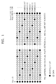
- scattered pilots are transmitted in the OFDM method. However, the scattered pilots are not transmitted through fixed sub channels, but are transmitted through different sub channels in every symbol, having a predetermined pattern, as shown in Figure 1.
- the scattered pilots are repeated using four symbols as one period. Since the scattered pilots are transmitted through the first and final sub channels in a 12 sub channel period, making a second starting point of every symbol different, the characteristics of all the entire sub channels are estimated by finding out positions to which the scattered pilots are transmitted, calculating estimated values according to the characteristics of all the sub channel, and obtaining the characteristics of the data sub channels between the scattered pilots by interpolating the estimated values of adjacent pilots.
- the distance between the scattered pilots becomes 11 sub channels, a compensation error becomes larger when frequency distortion is generated.
- a precise filter is required as an interpolating filter since there are 11 sub channels between the scattered pilots.
- An aim of at least preferred embodiments of the present invention is to provide an equalizing method for reducing the amount of calculation by reducing the distance between received scattered pilots and estimating channel characteristics.
- Another preferred aim of the present invention is to provide an equalizer of a simple structure in an OFDM receiver.
- Still another preferred aim of the present invention is to provide an equalizer for quickly compensating for the amplitude distortion and the phase delay of a channel in an OFDM receiver.
- an equalizing method for compensating for channel distortion of a plurality of carriers transmitted through a plurality of sub channels using scattered pilots having a period of a first predetermined number of symbols comprising the steps of (a) extracting scattered pilots in units of the first predetermined symbol period from a plurality of received carriers, adding a channel characteristic value of each sub channel in the extracted scattered pilot position in the first predetermined number of symbols, and obtaining channel characteristic values in scattered pilot position having a period of a second predetermined number, (b) estimating the characteristics of a sub channel through which data between scattered pilots is transmitted using the channel characteristic values in the scattered pilot position having the period of the adjacent second predetermined number to obtain all sub channel characteristic values, and (c) compensating for channel distortion of the received plurality of carriers on the basis of all the sub channel characteristic values.
- an equalizer for compensating for channel distortion of a plurality of carriers transmitted through a plurality of received sub channels using a scattered pilot having a period of a first predetermined number of symbols, comprising an estimating unit for extracting scattered pilots from the plurality of received carriers in units of the first predetermined number of symbols to estimate channel characteristic values in the extracted scattered pilot position, a calculating unit for obtaining channel characteristic values in the position of the scattered pilot of a period of a second predetermined number of sub channels by adding the channel characteristic values of each sub channel each other in units of the first predetermined number of symbols and for providing all the sub channel characteristic values by calculating the sub channel characteristics of the data between the scattered pilots using the channel characteristic values in the scattered pilot position of the period of the second predetermined number of sub channels, and a compensating unit for compensating for channel distortion of the plurality of received carriers using all the estimated sub channel characteristic values.
- the preferred embodiment of the present invention compensates for channel distortion by estimating the channel characteristics on the basis of a four symbol interval, assuming that the channel characteristics hardly change during the four symbol since the characteristics of the scattered pilot have a period of four symbols. Namely, since the time of the four symbol interval is about 4ms (in the case of an 8K mode), it is assumed that the channel characteristic gradually change during that time.
- STEP 1 it is determined which symbol is received among the four symbols and a scattered pilot is extracted from the received symbol.
- STEP 2 a channel characteristic value in the position of the extracted scattered pilot is estimated.
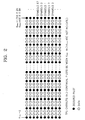
- STEP 3 the scattered pilot exists for a period of three sub channels, when a channel characteristic value with respect to one symbol to be used during a four symbol interval is obtained by inserting an arithmetic zero "0" into all the data except for the scattered pilots in units of four symbols in which the channel characteristic value in the position of the scattered pilot is estimated and by adding the characteristic values in each sub channel to each other in unit of four symbols. Therefore, the distribution of the modified scattered pilot provided in the present invention is as shown in Figure 2.
- STEP 4 the characteristics of two sub channels to which data between two adjacent scattered pilots is transmitted are estimated by interpolating the channel characteristic value of the position of the estimated scattered pilot.
- the characteristics of three sub channels are calculated in the same manner, considering that the characteristics of a sub channels to which the scattered pilot is transmitted are the same as those of the sub channels to which the following two data are transmitted, when interpolation hardly changes the characteristics of the sub channel.
- the characteristics of the two sub channels to which data between the scattered pilots are transmitted are calculated by a linear interpolation.
- a windowed finite impulse response (FIR) filter having a better interpolation performance is used.
- STEP 5 Distortion in a channel is compensated for by multiplying the transmitted sub channel data by the inverse of the characteristic value of the sub channel.
- the characteristics of the sub channels are the same over a four symbol unit. The characteristics of all the sub channels of one symbol, to which the channel characteristics in the respective scattered pilot positions of four symbols are considered, are applied to the four symbols, assuming that the channel characteristics do not change during the four symbol interval.
- Figure 3 shows the operation of an equalizer in a time domain, to aid understanding of the present invention.
- a plurality of carriers x 0 , x 1 , ..., x N-1 are mixed with the respective sub channel characteristics h 0 , h 1 , ..., h N-1 and are transmitted through a plurality of sub channels.
- the plurality of carriers transmitted through the plurality of sub channels, to which noise (the channel distortion) no, n 1 , ..., n N-1 is added, are input to the equalizer.
- the plurality of received carriers r 0 , r 1 , ..., r N-1 are multiplied by the inverse characteristics ( ⁇ h 0 - 1 , h 1 - 1 , ... , ⁇ h N - 1 - 1 ) of the respective sub channels, to output the plurality of compensated carriers ( ⁇ x 0 , x 1 , ... , ⁇ x N - 1 ) .
- Equation 1 Since the equalizer compensates for frequency distortion in a symbol unit in a frequency domain, the following equation 1 is obtained when the characteristics of a channel, transmitted data, and received data are H(f), x(f), and R(f), respectively.
- R k ( f ) H k ( f ) ⁇ X k ( f ) wherein, k represents the sub channel index.
- the sub channel through which a pilot is transmitted can be represented as the following equation 2.
- the amplitude characteristics and the phase characteristics of the sub channel can be obtained from the equation 3.
- R k ( f ) H k ( f ) ⁇ P k ( f ) wherein P(f) represents a scattered pilot.
- H k ( f ) R k ( f ) P k ( f )
- the number of sub channels obtained from the scattered pilots of a modified distribution shown in Figure 2 is 6816/3.
- the characteristics of the 6816x2/3 data channel are obtained by an interpolation using the characteristics of the sub channels.
- an interpolation by a windowed FIR filter can be used.
- the windowed FIR filter is designed using a low pass filter whose sampling frequency is three times a carrier frequency.
- the characteristics of the scattered pilot are filtered by the windowed FIR filter, the characteristics of the two sub channels between the scattered pilots are calculated and output. Namely, when the characteristics of the filter are F(f), the characteristics of all the channels are obtained by performing a convolution for the characteristics of the scattered pilot and those of the filter F(f). Namely; the characteristics of all the channels H(f) can be obtained as follows.
- H ( f ) H p ( f ) ⁇ F ( f )
- the equalized output represented in the equation 8 is obtained by obtaining the characteristics of all the sub channels by the method shown in the equation 7 and multiplying the received data by the inverse of the characteristic value of the sub channel.
- the position of the scattered pilot since the position of the scattered pilot does not change. It can be estimated the characteristics of the channel by calculating values between the scattered pilots by constant interpolation or linear interpolation, since the distance between the scattered pilots becomes two sub channels.
- interpolation by the windowed FIR filter can be used in order to enhance the interpolation performance.
- the equalization in the frequency domain can be performed by multiplying the received signal by the inverse of the channel characteristic value.
- the equalization becomes very simple since it has the structure of equalizer having one tap filter. Therefore, estimating the channel characteristics in the four symbol interval unit is advantageous with respect to the structure of the equalizer or the amount of calculation, if the channel characteristics hardly change during the four symbol interval.
- a guard interval remover 102 removes a cyclic prefix (CP) corresponding to a guard interval from the received data.
- a guard band remover 104 performs a fast Fourier transform (FFT) on data output from the guard interval remover 102 and removes the guard band included in the fast Fourier transformed data in units of one symbol, in order to convert the data into data of a frequency domain since the data output from the guard interval remover 102 is data of a time domain.
- FFT fast Fourier transform
- each symbol is formed of 6817 carriers.
- the symbols are transmitted over a duration of Ts.
- the duration Ts includes an effective symbol part interval for transmitting the 6817 carriers and a guard interval.
- a scattered pilot extractor 106 extracts the scattered pilot from data from which the guard band is removed output from the guard band remover 104, namely, the 6817 carriers in every symbol in the case of an 8K mode. Since the scattered pilots have a boosted power level, the scattered pilot extractor 106 examines a correlation between the data from which the guard band has been removed and a reference sequence, and extracts the scattered pilot. Since the reference sequence is one symbol pattern data among four symbols, it is possible to find out which is the symbol received at present among the four symbols. Since the scattered pilot is repeated with a four symbol period, the position of the scattered pilot of the four symbols is automatically revealed by revealing the position of the scattered pilot of one symbol. Therefore, it is possible to correctly reveal the position of the scattered pilot of one symbol using the reference sequence by the scattered pilot extractor 106. With respect to the next three symbols, the received level value is output in the already revealed position of the scattered pilot.
- the boosted power level of the received scattered pilot is (4/3) 2 .
- the scattered pilot according to the positions of the respective scattered pilots of the four symbol period during transmission has a coordinate value of (4/3,0) or (-4/3,0). Since this coordinate information is already revealed by a scattered pilot determiner 108, the coordinate value of the scattered pilot extracted from the scattered pilot extractor 106 is output to a channel estimator 110.
- the channel estimator 110 outputs the channel characteristic value in the position of the scattered pilot by channel estimating using a coordinate value representing the position of the scattered pilot output from the scattered pilot determiner 108. Namely, the channel estimator 110 compares the boosted level of the scattered pilot extracted by the scattered pilot extractor 106 with the original coordinate value and outputs a value (r) for compensating for the amplitude distortion and a value ( ⁇ ) for compensating for the phase distortion.
- a zero inserter 112 inserts the channel characteristic value in the position of the scattered pilot estimated by the channel estimator 110 and "zero" into the positions of carriers other than the scattered pilot.
- the zero inserter 112 includes a buffer for storing carriers of the four symbols. Therefore, the output of the zero inserter 112 has the distribution of the scattered pilot as shown in Figure 2 and values in the scattered pilot positions are channel characteristic values.
- An adder 114 adds the respective carriers output from the zero inserter 112 in units of four symbols and outputs the channel characteristic value of one symbol in the position of the pilot having a period of three sub channels.
- a coefficient interpolator 116 interpolates the channel characteristic value in the position of the pilot having the period of the three sub channels output from the channel estimator 110 using linear interpolation, constant interpolation, or windowed FIR filter interpolation and outputs the interpolated coefficients in order to estimate two sub channel characteristic value between the pilots.
- a counter may be included in the coefficient interpolator 116 in order to output the interpolated coefficient showing the characteristics of all the sub channels of one symbol four times in order to apply the characteristics of all the sub channels of one symbol to the four symbols.
- a frequency domain equalizer 118 can be a filter having one tap, namely, a multiplier.
- the frequency domain equalizer 118 outputs data compensated by multiplying the data output from the guard band remover 104 by the inverse of the coefficient estimated by the coefficient interpolator 116.
- a buffer could be included for buffering the output of the guard band remover 104 during the estimation of the channel characteristics of the four symbols by the coefficient interpolator 116 for controlling timing.
- the scattered pilot extractor 106 can be called an estimating unit.
- the zero inserter 112, the adder 114, and the coefficient interpolator 116 can together be called a calculating unit.
- the frequency domain equalizer 118 can be called a compensating unit.
Landscapes
- Engineering & Computer Science (AREA)
- Signal Processing (AREA)
- Computer Networks & Wireless Communication (AREA)
- Power Engineering (AREA)
- Cable Transmission Systems, Equalization Of Radio And Reduction Of Echo (AREA)
Claims (14)
- Procédé d'égalisation pour compenser une distorsion de canal d'une pluralité de porteuses transmises via une pluralité de sous-canaux en utilisant des ondes pilotes diffusées ayant une période d'un premier nombre prédéterminé de symboles, comportant les étapes consistant à :(a) extraire (106) des ondes pilotes diffusées en unités de la première période de symboles prédéterminée d'une pluralité de porteuses reçues, ajouter une valeur de caractéristique de canal de chaque sous-canal dans la position d'onde pilote diffusée extraite dans le premier nombre prédéterminé de symboles, et obtenir des valeurs de caractéristique de canal dans des positions d'onde pilote diffusée ayant une période d'un second nombre prédéterminé,(b) estimer (110) les caractéristiques d'un sous-canal à travers lequel des données entre des ondes pilotes diffusées sont transmises en utilisant les valeurs de caractéristique de canal dans la position d'onde pilote diffusée ayant la période du second nombre prédéterminé adjacent afin d'obtenir toutes les valeurs de caractéristique de sous-canal, et(c) compenser (118) une distorsion de canal de la pluralité de porteuses reçues sur la base de toutes les valeurs de caractéristique de sous-canal.
- Procédé selon la revendication 1, dans lequel l'étape (a) comporte les étapes consistant à :(a1) extraire des ondes pilotes diffusées d'une pluralité de porteuses reçues en unités du premier nombre prédéterminé de symboles,(a2) calculer chaque valeur de caractéristique de canal dans la position d'onde pilote diffusée extraite en utilisant les valeurs de coordonnées des ondes pilotes diffusées déjà révélées,(a3) remplacer des porteuses autres que les ondes pilotes diffusées par des données de motif prédéterminé, et(a4) ajouter les valeurs de caractéristique de chaque sous-canal les unes aux autres dans chaque unité du premier nombre prédéterminé de symboles afin d'obtenir chaque valeur de caractéristique de canal dans la position des ondes pilotes diffusées ayant la période d'un second nombre prédéterminé concernant un symbole.
- Procédé selon la revendication 1 ou 2, dans lequel toutes les valeurs de caractéristique de sous-canal sont appliquées à la pluralité de porteuses reçues pendant l'intervalle de symboles du premier nombre prédéterminé, à l'étape (c).
- Procédé selon la revendication 1, 2 ou 3, dans lequel les valeurs de caractéristique de canal dans la position des ondes pilotes diffusées ayant la période du second nombre prédéterminé adjacent sont interpolées par l'intermédiaire d'une interpolation prédéterminée et un coefficient interpolé est délivré en sortie, afin d'estimer les caractéristiques du sous-canal à travers lequel des données entre les ondes pilotes diffusées sont transmises, à l'étape (b).
- Procédé selon la revendication 4, dans lequel la distorsion de canal est compensée en multipliant la porteuse reçue pendant l'intervalle de symboles du premier nombre prédéterminé par l'inverse du coefficient interpolé.
- Procédé selon la revendication 4, dans lequel l'interpolation est l'une parmi une interpolation constante, une interpolation linéaire et une interpolation par filtrage FIR à fenêtre.
- Procédé selon l'une quelconque des revendications 2 à 6, dans lequel les données de motif prédéterminé sont des zéros arithmétiques.
- Egaliseur pour compenser une distorsion de canal d'une pluralité de porteuses transmises via une pluralité de sous-canaux reçus en utilisant une onde pilote diffusée ayant en période d'un premier nombre prédéterminé de symboles, comportant :une unité d'estimation (106) pour extraire des ondes pilotes diffusées de la pluralité de porteuses reçues en unités du premier nombre prédéterminé de symboles afin d'estimer des valeurs de caractéristique de canal dans la position d'onde pilote diffusée extraite,une unité de calcul (112, 114, 116) pour obtenir des valeurs de caractéristique de canal dans la position de l'onde pilote diffusée d'une période d'un second nombre prédéterminé de sous-canaux en ajoutant les valeurs de caractéristique de canal de chaque sous-canal les unes aux autres en unités du premier nombre prédéterminé de symboles et pour délivrer toutes les valeurs de caractéristique de sous-canal en calculant les caractéristiques de sous-canal des données entre les ondes pilotes diffusées en utilisant les valeurs de caractéristique de canal dans la position d'onde pilote diffusée de la période du second nombre prédéterminé de sous-canaux, etune unité de compensation (118) pour compenser une distorsion de canal de la pluralité de porteuses reçues en utilisant toutes les valeurs de caractéristique de sous-canal estimées.
- Egaliseur selon la revendication 8, dans lequel toutes les valeurs de caractéristique de sous-canal d'un symbole sont appliquées à la pluralité de porteuses reçues pendant un intervalle du premier nombre prédéterminé de symboles, dans l'unité de compensation (118).
- Egaliseur selon la revendication 8 ou 9, dans lequel l'unité de calcul effectue une interpolation des valeurs de caractéristique de canal dans la position de l'onde pilote diffusée ayant la période du second nombre prédéterminé de symboles adjacent et un coefficient interpolé est délivré en sortie, afin de calculer la caractéristique du sous-canal à travers lequel des données entre les ondes pilotes diffusées sont transmises.
- Egaliseur selon la revendication 10, dans lequel l'unité de compensation (118) comporte un multiplicateur pour multiplier la porteuse reçue par l'inverse du coefficient interpolé.
- Egaliseur selon la revendication 10, dans lequel l'interpolation est l'une parmi une interpolation constante, une interpolation linéaire, et une interpolation par filtrage FIR à fenêtre.
- Egaliseur selon la revendication 12, dans lequel le filtre FIR à fenêtre est un filtre passe-bas dont la fréquence d'échantillonnage est égale au second nombre prédéterminé de fois la fréquence porteuse.
- Egaliseur selon la revendication 8, dans lequel l'unité de calcul (112, 114) insère un "zéro" arithmétique dans les porteuses autres que les ondes pilotes diffusées ayant les valeurs de caractéristique de canal estimées et ajoute les valeurs de caractéristique de chaque sous-canal les unes aux autres en unité du premier nombre prédéterminé de symboles.
Applications Claiming Priority (2)
| Application Number | Priority Date | Filing Date | Title |
|---|---|---|---|
| KR1019970039660A KR100224863B1 (ko) | 1997-08-20 | 1997-08-20 | Ofdm 수신기를 위한 등화 방법과 등화기 |
| KR9739660 | 1997-08-20 |
Publications (3)
| Publication Number | Publication Date |
|---|---|
| EP0903898A2 EP0903898A2 (fr) | 1999-03-24 |
| EP0903898A3 EP0903898A3 (fr) | 2001-05-16 |
| EP0903898B1 true EP0903898B1 (fr) | 2006-02-15 |
Family
ID=36710035
Family Applications (1)
| Application Number | Title | Priority Date | Filing Date |
|---|---|---|---|
| EP98306337A Expired - Lifetime EP0903898B1 (fr) | 1997-08-20 | 1998-08-07 | Procedé et dispositif d'égalisation pour un récepteur OFDM |
Country Status (5)
| Country | Link |
|---|---|
| EP (1) | EP0903898B1 (fr) |
| JP (1) | JPH11163771A (fr) |
| KR (1) | KR100224863B1 (fr) |
| CN (1) | CN1110148C (fr) |
| DE (1) | DE69833477T2 (fr) |
Families Citing this family (30)
| Publication number | Priority date | Publication date | Assignee | Title |
|---|---|---|---|---|
| GB2340000B (en) * | 1998-07-02 | 2003-06-18 | Lsi Logic Corp | Storing digital video braodcast signals |
| US6292511B1 (en) * | 1998-10-02 | 2001-09-18 | Usa Digital Radio Partners, Lp | Method for equalization of complementary carriers in an AM compatible digital audio broadcast system |
| FR2799597B1 (fr) | 1999-10-08 | 2004-02-20 | Mitsubishi Electric Inf Tech | Procede de transmission de donnees sur porteuses multiples d'un emetteur a un recepteur et recepteur prevu pour la mise en oeuvre dudit procede |
| US6650617B1 (en) * | 2000-02-22 | 2003-11-18 | Thomson Licensing S.A. | Reduced complexity FFT window synchronization for an orthogonal frequency division multiplexing system |
| US6771591B1 (en) | 2000-07-31 | 2004-08-03 | Thomson Licensing S.A. | Method and system for processing orthogonal frequency division multiplexed signals |
| DE1313242T1 (de) * | 2000-08-21 | 2003-11-27 | Kabushiki Kaisha Kenwood, Tokio/Tokyo | Orthogonal-frequenzmultiplex-signalempfangsvorrichtung und orthogonal-frequenzmultiplex-signalempfangsverfahren |
| SE0004403L (sv) * | 2000-11-29 | 2002-05-30 | Ericsson Telefon Ab L M | Metoder och anordningar i ett telekommunikationssystem |
| DE10060569B4 (de) * | 2000-12-06 | 2004-05-27 | Robert Bosch Gmbh | Verfahren zur kohärenten Demodulation von Funksignalen |
| KR100397353B1 (ko) * | 2001-02-07 | 2003-09-13 | 광주과학기술원 | Ofdm 시스템용 원-탭 등화기뱅크의 신호왜곡 보상방법 |
| GB2386519B (en) | 2002-03-12 | 2004-05-26 | Toshiba Res Europ Ltd | Adaptive Multicarrier Communication |
| TW200401522A (en) * | 2002-05-17 | 2004-01-16 | Matsushita Electric Industrial Co Ltd | Receiving device and receiving method and transmission path characteristic measurement device |
| KR100824367B1 (ko) * | 2002-05-24 | 2008-04-22 | 삼성전자주식회사 | Ofdm 송신기 및 그의 신호처리방법 |
| CN100442681C (zh) * | 2002-10-11 | 2008-12-10 | 松下电器产业株式会社 | 环路干扰消除器、中继系统和环路干扰消除方法 |
| JP4464651B2 (ja) * | 2002-10-11 | 2010-05-19 | パナソニック株式会社 | 回り込みキャンセラ、中継システム及び回り込みキャンセル方法 |
| US7830970B2 (en) | 2003-06-11 | 2010-11-09 | Nxp B.V. | Receiver for a multi-carrier communication system |
| EP1499081A3 (fr) * | 2003-07-18 | 2007-01-03 | Broadcom Corporation | Structure d'un signal multiporteuse |
| AU2003262613A1 (en) * | 2003-09-22 | 2005-04-11 | Nokia Corporation | Method, system and receiver in receiving a multi-carrier transmission |
| JP3952200B2 (ja) | 2003-10-28 | 2007-08-01 | カシオ計算機株式会社 | ダイバーシティを用いたofdm受信装置、ダイバーシティを用いたofdm受信回路及びダイバーシティを用いたofdm受信方法 |
| JP2006042025A (ja) * | 2004-07-28 | 2006-02-09 | Casio Comput Co Ltd | Ofdm信号復調回路及びofdm信号復調方法 |
| KR100594085B1 (ko) | 2004-12-21 | 2006-06-30 | 삼성전자주식회사 | 직교 주파수 분할 다중 시스템에서 시간영역 채널 추정방법 및 장치 |
| JP4971172B2 (ja) * | 2005-03-01 | 2012-07-11 | パナソニック株式会社 | 受信装置、集積回路及び受信方法 |
| JP4776311B2 (ja) * | 2005-09-09 | 2011-09-21 | Okiセミコンダクタ株式会社 | 尤度補正器及び尤度補正方法 |
| JP2007081504A (ja) * | 2005-09-12 | 2007-03-29 | Hitachi Kokusai Electric Inc | Ofdm受信機における伝送路特性補間方法及びその装置 |
| EP2068520A1 (fr) | 2007-12-07 | 2009-06-10 | Alcatel Lucent | Moniteur de canal de récepteur OFDM optique |
| KR101021306B1 (ko) * | 2008-12-19 | 2011-03-11 | 한국전자통신연구원 | Mimo 및 ofdm 전송 방식을 지원하는 단말 복조 시스템 및 그 제어방법 |
| JP2011044782A (ja) * | 2009-08-19 | 2011-03-03 | Panasonic Corp | 無線送信装置及び無線送信方法 |
| KR101688203B1 (ko) * | 2009-09-18 | 2016-12-21 | 에스케이텔레콤 주식회사 | 느린 시변 채널용 수신 장치 및 방법 |
| JP5005803B2 (ja) * | 2010-08-25 | 2012-08-22 | Kddi株式会社 | 伝送路推定装置および伝送路推定プログラム |
| CN102088425A (zh) * | 2011-03-08 | 2011-06-08 | 中兴通讯股份有限公司 | Mimo系统中信道估计及插入导频的方法、装置和系统 |
| CN109873781A (zh) * | 2017-12-01 | 2019-06-11 | 晨星半导体股份有限公司 | 符合同轴电缆多媒体联盟标准的信号接收装置及其信号处理方法 |
Family Cites Families (2)
| Publication number | Priority date | Publication date | Assignee | Title |
|---|---|---|---|---|
| FR2738095B1 (fr) * | 1995-08-21 | 1997-11-07 | France Telecom | Procede et dispositif de demodulation d'un signal multiporteuse tenant compte d'une estimation de la reponse du canal de transmission et d'une estimaton d'une distorsion blanche en frequence |
| FR2743967B1 (fr) * | 1996-01-18 | 1998-03-27 | France Telecom | Procede et dispositif de synchronisation temporelle d'un recepteur d'un signal multiporteuse |
-
1997
- 1997-08-20 KR KR1019970039660A patent/KR100224863B1/ko not_active Expired - Fee Related
-
1998
- 1998-08-04 JP JP10220784A patent/JPH11163771A/ja active Pending
- 1998-08-07 DE DE69833477T patent/DE69833477T2/de not_active Expired - Lifetime
- 1998-08-07 EP EP98306337A patent/EP0903898B1/fr not_active Expired - Lifetime
- 1998-08-19 CN CN98118458A patent/CN1110148C/zh not_active Expired - Fee Related
Also Published As
| Publication number | Publication date |
|---|---|
| KR100224863B1 (ko) | 1999-10-15 |
| DE69833477T2 (de) | 2006-08-10 |
| JPH11163771A (ja) | 1999-06-18 |
| EP0903898A2 (fr) | 1999-03-24 |
| CN1110148C (zh) | 2003-05-28 |
| CN1209001A (zh) | 1999-02-24 |
| DE69833477D1 (de) | 2006-04-20 |
| KR19990016930A (ko) | 1999-03-15 |
| EP0903898A3 (fr) | 2001-05-16 |
Similar Documents
| Publication | Publication Date | Title |
|---|---|---|
| EP0903898B1 (fr) | Procedé et dispositif d'égalisation pour un récepteur OFDM | |
| EP0898381B1 (fr) | Méthode d'égalisation et égaliseur pour un récepteur de signaux OFDM | |
| KR101339425B1 (ko) | Ici 추정 방법 및 ici 저감 등화기 | |
| EP1496659A1 (fr) | Dispositif et méthode pour la transmission et réception dans un système de communication MDFO avec une extension cyclique insuffisant | |
| EP1551120A1 (fr) | Dispositif de reception, procede de reception, et dispositif de mesure des caracteristiques d'un canal de transmission | |
| US8345782B2 (en) | Method and apparatus for channel estimation | |
| US20100290570A1 (en) | Method and apparatus for channel estimation in ofdm | |
| US20030058953A1 (en) | Receiver of an orthogonal frequency division multiplexing system | |
| US20070076804A1 (en) | Image-rejecting channel estimator, method of image-rejection channel estimating and an OFDM receiver employing the same | |
| GB2448097A (en) | Transmission path estimation device, equalisation device, and radio system | |
| US20060017613A1 (en) | High doppler channel estimation for OFD multiple antenna systems | |
| KR100664600B1 (ko) | Ofdm 시스템의 곡선접합 채널추정 방법 | |
| KR100338733B1 (ko) | Ofdm수신기를위한등화방법과등화기 | |
| US8139664B2 (en) | Reception apparatus, reception method and program | |
| EP2169891A2 (fr) | Processeur d'informations ainsi que procédé, dispositif d'affichage et programme correspondant | |
| EP1821407B1 (fr) | Système d'estimation de canal d'OFDM | |
| KR950012821B1 (ko) | 디지탈 비순환형 필터 형태의 등화기를 갖는 vhf카 라디오 | |
| EP2077625B1 (fr) | Filtre et récepteur de correspondance | |
| JP2004229198A (ja) | Ofdm復調方法及びofdm復調装置 | |
| KR20030042377A (ko) | 직교 주파수 분할 다중화 신호의 주파수 오프셋 추정 장치및 그 방법 | |
| KR100986166B1 (ko) | Dft를 이용하여 채널을 추정하는 dvb 시스템과 dvb 시스템의 채널 추정 방법 | |
| KR100977557B1 (ko) | 직교 주파수 분할 다중화 시스템의 시변 채널 추정 장치 및방법 | |
| CN120934968A (zh) | 时变频率选择性衰落信道中加窗ofdm系统的迭代信道估计和信号解码方法 |
Legal Events
| Date | Code | Title | Description |
|---|---|---|---|
| PUAI | Public reference made under article 153(3) epc to a published international application that has entered the european phase |
Free format text: ORIGINAL CODE: 0009012 |
|
| 17P | Request for examination filed |
Effective date: 19980817 |
|
| AK | Designated contracting states |
Kind code of ref document: A2 Designated state(s): DE FR GB |
|
| AX | Request for extension of the european patent |
Free format text: AL;LT;LV;MK;RO;SI |
|
| PUAL | Search report despatched |
Free format text: ORIGINAL CODE: 0009013 |
|
| AK | Designated contracting states |
Kind code of ref document: A3 Designated state(s): AT BE CH CY DE DK ES FI FR GB GR IE IT LI LU MC NL PT SE |
|
| AX | Request for extension of the european patent |
Free format text: AL;LT;LV;MK;RO;SI |
|
| AKX | Designation fees paid |
Free format text: DE FR GB |
|
| 17Q | First examination report despatched |
Effective date: 20040924 |
|
| GRAC | Information related to communication of intention to grant a patent modified |
Free format text: ORIGINAL CODE: EPIDOSCIGR1 |
|
| GRAP | Despatch of communication of intention to grant a patent |
Free format text: ORIGINAL CODE: EPIDOSNIGR1 |
|
| GRAS | Grant fee paid |
Free format text: ORIGINAL CODE: EPIDOSNIGR3 |
|
| GRAA | (expected) grant |
Free format text: ORIGINAL CODE: 0009210 |
|
| AK | Designated contracting states |
Kind code of ref document: B1 Designated state(s): DE FR GB |
|
| REG | Reference to a national code |
Ref country code: GB Ref legal event code: FG4D |
|
| REF | Corresponds to: |
Ref document number: 69833477 Country of ref document: DE Date of ref document: 20060420 Kind code of ref document: P |
|
| ET | Fr: translation filed | ||
| PLBE | No opposition filed within time limit |
Free format text: ORIGINAL CODE: 0009261 |
|
| STAA | Information on the status of an ep patent application or granted ep patent |
Free format text: STATUS: NO OPPOSITION FILED WITHIN TIME LIMIT |
|
| 26N | No opposition filed |
Effective date: 20061116 |
|
| REG | Reference to a national code |
Ref country code: FR Ref legal event code: PLFP Year of fee payment: 18 |
|
| PGFP | Annual fee paid to national office [announced via postgrant information from national office to epo] |
Ref country code: DE Payment date: 20150722 Year of fee payment: 18 Ref country code: GB Payment date: 20150721 Year of fee payment: 18 |
|
| PGFP | Annual fee paid to national office [announced via postgrant information from national office to epo] |
Ref country code: FR Payment date: 20150625 Year of fee payment: 18 |
|
| REG | Reference to a national code |
Ref country code: DE Ref legal event code: R119 Ref document number: 69833477 Country of ref document: DE |
|
| GBPC | Gb: european patent ceased through non-payment of renewal fee |
Effective date: 20160807 |
|
| REG | Reference to a national code |
Ref country code: FR Ref legal event code: ST Effective date: 20170428 |
|
| PG25 | Lapsed in a contracting state [announced via postgrant information from national office to epo] |
Ref country code: DE Free format text: LAPSE BECAUSE OF NON-PAYMENT OF DUE FEES Effective date: 20170301 Ref country code: FR Free format text: LAPSE BECAUSE OF NON-PAYMENT OF DUE FEES Effective date: 20160831 Ref country code: GB Free format text: LAPSE BECAUSE OF NON-PAYMENT OF DUE FEES Effective date: 20160807 |