EP0904193B1 - Vorrichtung zur herstellen von verpackungsbehältern aus zuschnitten aus kunstharz - Google Patents
Vorrichtung zur herstellen von verpackungsbehältern aus zuschnitten aus kunstharz Download PDFInfo
- Publication number
- EP0904193B1 EP0904193B1 EP97916593A EP97916593A EP0904193B1 EP 0904193 B1 EP0904193 B1 EP 0904193B1 EP 97916593 A EP97916593 A EP 97916593A EP 97916593 A EP97916593 A EP 97916593A EP 0904193 B1 EP0904193 B1 EP 0904193B1
- Authority
- EP
- European Patent Office
- Prior art keywords
- station
- blank
- flaps
- machine
- heads
- Prior art date
- Legal status (The legal status is an assumption and is not a legal conclusion. Google has not performed a legal analysis and makes no representation as to the accuracy of the status listed.)
- Expired - Lifetime
Links
- 229920003002 synthetic resin Polymers 0.000 title claims abstract description 12
- 239000000057 synthetic resin Substances 0.000 title claims abstract description 12
- 238000010438 heat treatment Methods 0.000 claims abstract description 51
- 238000003466 welding Methods 0.000 claims abstract description 11
- 230000004913 activation Effects 0.000 claims description 2
- 239000000463 material Substances 0.000 description 7
- 238000004519 manufacturing process Methods 0.000 description 6
- 239000003292 glue Substances 0.000 description 4
- 238000000034 method Methods 0.000 description 4
- 230000002146 bilateral effect Effects 0.000 description 2
- 239000004033 plastic Substances 0.000 description 2
- 238000004064 recycling Methods 0.000 description 2
- 230000001154 acute effect Effects 0.000 description 1
- 238000004026 adhesive bonding Methods 0.000 description 1
- 239000011248 coating agent Substances 0.000 description 1
- 238000000576 coating method Methods 0.000 description 1
- 238000013021 overheating Methods 0.000 description 1
- 239000011087 paperboard Substances 0.000 description 1
- 229920001169 thermoplastic Polymers 0.000 description 1
- 239000004416 thermosoftening plastic Substances 0.000 description 1
- 238000002604 ultrasonography Methods 0.000 description 1
- 238000011144 upstream manufacturing Methods 0.000 description 1
Images




Classifications
-
- B—PERFORMING OPERATIONS; TRANSPORTING
- B29—WORKING OF PLASTICS; WORKING OF SUBSTANCES IN A PLASTIC STATE IN GENERAL
- B29C—SHAPING OR JOINING OF PLASTICS; SHAPING OF MATERIAL IN A PLASTIC STATE, NOT OTHERWISE PROVIDED FOR; AFTER-TREATMENT OF THE SHAPED PRODUCTS, e.g. REPAIRING
- B29C53/00—Shaping by bending, folding, twisting, straightening or flattening; Apparatus therefor
- B29C53/80—Component parts, details or accessories; Auxiliary operations
- B29C53/84—Heating or cooling
-
- B—PERFORMING OPERATIONS; TRANSPORTING
- B31—MAKING ARTICLES OF PAPER, CARDBOARD OR MATERIAL WORKED IN A MANNER ANALOGOUS TO PAPER; WORKING PAPER, CARDBOARD OR MATERIAL WORKED IN A MANNER ANALOGOUS TO PAPER
- B31B—MAKING CONTAINERS OF PAPER, CARDBOARD OR MATERIAL WORKED IN A MANNER ANALOGOUS TO PAPER
- B31B50/00—Making rigid or semi-rigid containers, e.g. boxes or cartons
- B31B50/26—Folding sheets, blanks or webs
- B31B50/44—Folding sheets, blanks or webs by plungers moving through folding dies
- B31B50/46—Folding sheets, blanks or webs by plungers moving through folding dies and interconnecting side walls
-
- B—PERFORMING OPERATIONS; TRANSPORTING
- B29—WORKING OF PLASTICS; WORKING OF SUBSTANCES IN A PLASTIC STATE IN GENERAL
- B29C—SHAPING OR JOINING OF PLASTICS; SHAPING OF MATERIAL IN A PLASTIC STATE, NOT OTHERWISE PROVIDED FOR; AFTER-TREATMENT OF THE SHAPED PRODUCTS, e.g. REPAIRING
- B29C53/00—Shaping by bending, folding, twisting, straightening or flattening; Apparatus therefor
- B29C53/02—Bending or folding
- B29C53/04—Bending or folding of plates or sheets
-
- B—PERFORMING OPERATIONS; TRANSPORTING
- B29—WORKING OF PLASTICS; WORKING OF SUBSTANCES IN A PLASTIC STATE IN GENERAL
- B29C—SHAPING OR JOINING OF PLASTICS; SHAPING OF MATERIAL IN A PLASTIC STATE, NOT OTHERWISE PROVIDED FOR; AFTER-TREATMENT OF THE SHAPED PRODUCTS, e.g. REPAIRING
- B29C65/00—Joining or sealing of preformed parts, e.g. welding of plastics materials; Apparatus therefor
- B29C65/02—Joining or sealing of preformed parts, e.g. welding of plastics materials; Apparatus therefor by heating, with or without pressure
- B29C65/10—Joining or sealing of preformed parts, e.g. welding of plastics materials; Apparatus therefor by heating, with or without pressure using hot gases (e.g. combustion gases) or flames coming in contact with at least one of the parts to be joined
-
- B—PERFORMING OPERATIONS; TRANSPORTING
- B29—WORKING OF PLASTICS; WORKING OF SUBSTANCES IN A PLASTIC STATE IN GENERAL
- B29C—SHAPING OR JOINING OF PLASTICS; SHAPING OF MATERIAL IN A PLASTIC STATE, NOT OTHERWISE PROVIDED FOR; AFTER-TREATMENT OF THE SHAPED PRODUCTS, e.g. REPAIRING
- B29C66/00—General aspects of processes or apparatus for joining preformed parts
- B29C66/40—General aspects of joining substantially flat articles, e.g. plates, sheets or web-like materials; Making flat seams in tubular or hollow articles; Joining single elements to substantially flat surfaces
- B29C66/41—Joining substantially flat articles ; Making flat seams in tubular or hollow articles
- B29C66/43—Joining a relatively small portion of the surface of said articles
- B29C66/431—Joining the articles to themselves
-
- B—PERFORMING OPERATIONS; TRANSPORTING
- B29—WORKING OF PLASTICS; WORKING OF SUBSTANCES IN A PLASTIC STATE IN GENERAL
- B29C—SHAPING OR JOINING OF PLASTICS; SHAPING OF MATERIAL IN A PLASTIC STATE, NOT OTHERWISE PROVIDED FOR; AFTER-TREATMENT OF THE SHAPED PRODUCTS, e.g. REPAIRING
- B29C66/00—General aspects of processes or apparatus for joining preformed parts
- B29C66/80—General aspects of machine operations or constructions and parts thereof
- B29C66/83—General aspects of machine operations or constructions and parts thereof characterised by the movement of the joining or pressing tools
- B29C66/834—General aspects of machine operations or constructions and parts thereof characterised by the movement of the joining or pressing tools moving with the parts to be joined
- B29C66/8341—Roller, cylinder or drum types; Band or belt types; Ball types
- B29C66/83411—Roller, cylinder or drum types
-
- B—PERFORMING OPERATIONS; TRANSPORTING
- B29—WORKING OF PLASTICS; WORKING OF SUBSTANCES IN A PLASTIC STATE IN GENERAL
- B29C—SHAPING OR JOINING OF PLASTICS; SHAPING OF MATERIAL IN A PLASTIC STATE, NOT OTHERWISE PROVIDED FOR; AFTER-TREATMENT OF THE SHAPED PRODUCTS, e.g. REPAIRING
- B29C66/00—General aspects of processes or apparatus for joining preformed parts
- B29C66/80—General aspects of machine operations or constructions and parts thereof
- B29C66/83—General aspects of machine operations or constructions and parts thereof characterised by the movement of the joining or pressing tools
- B29C66/834—General aspects of machine operations or constructions and parts thereof characterised by the movement of the joining or pressing tools moving with the parts to be joined
- B29C66/8341—Roller, cylinder or drum types; Band or belt types; Ball types
- B29C66/83411—Roller, cylinder or drum types
- B29C66/83417—Roller, cylinder or drum types said rollers, cylinders or drums being hollow
-
- B—PERFORMING OPERATIONS; TRANSPORTING
- B29—WORKING OF PLASTICS; WORKING OF SUBSTANCES IN A PLASTIC STATE IN GENERAL
- B29C—SHAPING OR JOINING OF PLASTICS; SHAPING OF MATERIAL IN A PLASTIC STATE, NOT OTHERWISE PROVIDED FOR; AFTER-TREATMENT OF THE SHAPED PRODUCTS, e.g. REPAIRING
- B29C66/00—General aspects of processes or apparatus for joining preformed parts
- B29C66/01—General aspects dealing with the joint area or with the area to be joined
- B29C66/05—Particular design of joint configurations
- B29C66/10—Particular design of joint configurations particular design of the joint cross-sections
- B29C66/11—Joint cross-sections comprising a single joint-segment, i.e. one of the parts to be joined comprising a single joint-segment in the joint cross-section
- B29C66/112—Single lapped joints
- B29C66/1122—Single lap to lap joints, i.e. overlap joints
-
- B—PERFORMING OPERATIONS; TRANSPORTING
- B29—WORKING OF PLASTICS; WORKING OF SUBSTANCES IN A PLASTIC STATE IN GENERAL
- B29L—INDEXING SCHEME ASSOCIATED WITH SUBCLASS B29C, RELATING TO PARTICULAR ARTICLES
- B29L2031/00—Other particular articles
- B29L2031/712—Containers; Packaging elements or accessories, Packages
- B29L2031/7162—Boxes, cartons, cases
-
- B—PERFORMING OPERATIONS; TRANSPORTING
- B31—MAKING ARTICLES OF PAPER, CARDBOARD OR MATERIAL WORKED IN A MANNER ANALOGOUS TO PAPER; WORKING PAPER, CARDBOARD OR MATERIAL WORKED IN A MANNER ANALOGOUS TO PAPER
- B31B—MAKING CONTAINERS OF PAPER, CARDBOARD OR MATERIAL WORKED IN A MANNER ANALOGOUS TO PAPER
- B31B2100/00—Rigid or semi-rigid containers made by folding single-piece sheets, blanks or webs
-
- B—PERFORMING OPERATIONS; TRANSPORTING
- B31—MAKING ARTICLES OF PAPER, CARDBOARD OR MATERIAL WORKED IN A MANNER ANALOGOUS TO PAPER; WORKING PAPER, CARDBOARD OR MATERIAL WORKED IN A MANNER ANALOGOUS TO PAPER
- B31B—MAKING CONTAINERS OF PAPER, CARDBOARD OR MATERIAL WORKED IN A MANNER ANALOGOUS TO PAPER
- B31B2120/00—Construction of rigid or semi-rigid containers
- B31B2120/502—Construction of rigid or semi-rigid containers having integral corner posts or reinforcements
-
- B—PERFORMING OPERATIONS; TRANSPORTING
- B31—MAKING ARTICLES OF PAPER, CARDBOARD OR MATERIAL WORKED IN A MANNER ANALOGOUS TO PAPER; WORKING PAPER, CARDBOARD OR MATERIAL WORKED IN A MANNER ANALOGOUS TO PAPER
- B31B—MAKING CONTAINERS OF PAPER, CARDBOARD OR MATERIAL WORKED IN A MANNER ANALOGOUS TO PAPER
- B31B50/00—Making rigid or semi-rigid containers, e.g. boxes or cartons
- B31B50/60—Uniting opposed surfaces or edges; Taping
- B31B50/64—Uniting opposed surfaces or edges; Taping by applying heat or pressure, e.g. by welding
-
- B—PERFORMING OPERATIONS; TRANSPORTING
- B31—MAKING ARTICLES OF PAPER, CARDBOARD OR MATERIAL WORKED IN A MANNER ANALOGOUS TO PAPER; WORKING PAPER, CARDBOARD OR MATERIAL WORKED IN A MANNER ANALOGOUS TO PAPER
- B31B—MAKING CONTAINERS OF PAPER, CARDBOARD OR MATERIAL WORKED IN A MANNER ANALOGOUS TO PAPER
- B31B50/00—Making rigid or semi-rigid containers, e.g. boxes or cartons
- B31B50/74—Auxiliary operations
- B31B50/81—Forming or attaching accessories, e.g. opening devices, closures or tear strings
Definitions
- the present invention relates to production of box containers from blanks of synthetic resin.
- open box containers are usually obtained from a flat blank with suitable longitudinal and transversal creasing lines, which define folding lines for the container.
- these creasing lines define the bottom, the sides and the heads of a box container and form also four folds, connected in pairs to the heads by longitudinal creasing lines, so as to form, near the corners of the container, respective tubular stiffening elements, of triangular section.
- the container is appropriately resistant to crushing.
- each of these stiffening elements is formed by three consecutive flaps, arranged angularly one to another and obtained by other longitudinal creasing lines made in the above mentioned folds.
- the internal flap is folded perpendicular to the head and attached to a side of the box being formed, then the intermediate flap is folded slant toward the head and the outer flap is folded, in direction opposite the corner formed by the side and head, and made integral with the corresponding head of the container.
- Known machines for production of the aforementioned containers withdraw, stepwise one by one, the blanks from a magazine and then transport them through a series of intermediate stations, in which a plurality of folding means are situated.
- the blanks arrive at a final forming station, provided with further folding means, where the container forming operation is completed.
- the aforementioned folding means define, in suitable time relation, the sides and the heads of the container, as well as the tubular stiffening elements.
- the surfaces of the parts to be joined are usually glued together.
- one of the advantages deriving form the use of the aforementioned plastic materials is the possibility of their complete recycling, which from one side reduces the impact on the environment, and from the other side makes the containers cheaper.
- containers made of synthetic resin can be heat-welded by ultrasounds devices.
- surfaces to be joined are conducted near to heating means, which heat them uniformly until a predetermined temperature is reached; then the above mentioned surfaces are drawn one to the other and, finally presser means are applied thereto on the outside so as to uniformly press them for a predetermined time, in order to join them by heat-welding.
- the US-A-2.818.484 relates to box making machinery, particularly to machine for making boxes from thermoplastic sheet material.
- a blank provided with flaps and tabs is erected and then the tabs are welded to contiguous portions of the flaps by means of electrodes arranged in pairs at each corner of the box being formed. While activated, the electrodes exert a clamping action upon the portions and tabs attached thereto.
- Heat for welding is obtained by means of high frequency impulses generated by a suitable electronic device.
- the US-A-3.801.266 describes a machine for conveying container bodies formed from paperboard.
- the blanks have applied thereto a material that makes them capable of being welded by application of heat.
- the machine includes a nozzle for directing heated air against the surfaces to be welded.
- An external source provides hot air for welding.
- this machine is expensive and complicated, because it uses an external source of heat air, so that particular means are necessary to divert hot air when the conveyor ceases its motion, not to overheat the container being welded.
- These means include a valve operated by a solenoid.
- the external source causes heat leakage, so that a higher temperature is necessary to obtain the suitable heating of the surfaces to be welded, thus increasing the risk of overheating.
- the heating device disclosed in the US-A-3.801.266 is used to produce box containers in which the flaps are secured to the box bodies with the help of a heat activatable coating.
- the temperature reached by the heating device is low, because of the air diversion provided between the hot air generator and the nozzle. This device could not be used for securing the flaps to the box body without heat activatable glue.
- the object of the present invention is to propose a machine which produces box containers from blanks without using other materials, in particular forming stiffening elements for the containers in a simple and practical way, that means without complicated and expensive devices which have at the same time high production capacity and small dimensions. This is obtained by means of heating means reduced in their dimension because of a more compacted form and more effective working, with particular reference to the heated air external source of the prior art.
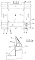
- This blank has longitudinal and transversal creasing lines 2, 3 and transversal splits 4 forming the bottom 5, the sides 6 and the heads 7 of a relative box container.
- the extensions 2a of the longitudinal creasing lines 2 defining the corners 8 of the box container form four folds 9, pairs of which are connected to said heads 7.
- Each fold 9 features two longitudinal creasing lines 2b, 2c defining three consecutive flaps 11a, 11b, 11c, inner, central and outer, respectively.
- the inner flap 11a is folded along the creasing 2a, at a right angle with respect to the relative head 7.
- the central flap 11b is folded about the creasing 2b so as to define an acute angle with respect to the inner flap 11a.
- the outer flap 11c is folded along the creasing line 2c, preferably in the direction opposite to the corner 8.
- This flap 11c is fastened to the relative head 7, as will be described in detail in the following, so as to define a tubular stiffening element, indicated with 20.
- the relative side 6 is fastened to the inner flap 11a, as will be described in detail in the following.
- this side 6 features an opening 6a.
- a magazine, containing a pack P of said blanks 10 in almost vertical position is indicated with 12.
- a pair of gripping devices 13a,13b, operated in suitable mutual time relation, are situated in front of the base of the blanks pack.
- the gripping means 13a,13b include respectively suction cup means 14 carried by relative actuator means 15, e.g. pneumatic jacks.
- the actuator means 15 translate the suction cups 14 from a position, in which they hold the base blank of the pack P and which is indicated with broken line in fig. 2, and a withdrawing position in the region of a station Z, in which the blank is kept in perfect vertical position by suitable stop means, not shown.
- First, second and third conveying means 30, 40 and 50 convey the blank 10, still maintained in perfect vertical position, to a final forming station 100.
- the blank 10 passes through a first and a second intermediate forming station S1, S2, in which stiffening elements 20 of the box container are formed, as will be explained in the following.
- the first conveying means 30 are made up of a close-loop chain 31, which turns around respective sprockets 32 having vertical axes.
- the pliers 16 of known type and known opening and closing operation technique, are fastened to this chain 31.
- the chain 31 is driven in time relation with the positioning of a blank in the station Z; in particular the pliers 16 are activated when they are situated near the front edge of the blank, so as to grip it.
- the second conveying means 40 are formed by a pair of identical chains 41, arranged on both sides of the chain 31 of the first conveying means 30 and moving with the same speed as said chain 31.
- the close-loop chains 41 turn around respective sprockets 42 having vertical axes.
- the rear sprockets 42 are coaxial with the corresponding sprocket 32 of the chain 31 of the first conveying means 30.
- the chains 41 are much longer than the chain 31 of the first conveying means 30.
- Respective lugs are so positioned with respect to the pliers 16 as to intercept the rear edge of the blank 10.
- the pliers 16 When near the front head of the chain 31, the pliers 16 are deactivated, so from this point, the blank 10 is translated by pushing action of the lugs.
- the third conveying means 50 are made up of a slide 51, equipped with at least one lug 52 and moving, in known, not shown way, between a rear station and a fore station.
- the slide 51 is operated in time relation with said second conveying means 40, so as to push the blank 10 to the final forming station 90.
- Handling means 46 seen in fig. 5, fastened to the chains 44, fold the flaps 11 a, 11 b and 11 c of the folds 9 so as to obtain the tubular stiffening elements 20, as described and illustrated in the Patent Applications BO92A 000170, BO92A 000302 of the same Applicant.
- the station S1 features a pair of first heating means 60, which heat the flaps 11c and corresponding areas of the heads 7 to a predetermined temperature, so that they can be joined to each other by heat-welding.
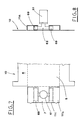
- These first heating means 60 feature respectively a heating body 61, that supplies a flow of hot air, and which is connected to a tubular arm 62.
- the tubular arm 62 is folded, so that it assumes substantially a U-form, and is provided, at its extremities, with two nozzles 63, 64 for delivering this flow of hot air.
- the shape of the nozzles 63, 64 substantially corresponds to the form of the area to heat, in particular extends according to the shape of the flaps 11c.
- Figure 6 shows a possible embodiment of the above mentioned heating body 61.
- This heating body 61 includes a case 65, of e.g. cylindrical shape, defining a labyrinth-like path 66, along which the air to be heated passes, delivered by an axial pipe 67.
- the delivered flow of air passes through a resistor 68, situated inside the case 65.
- the heated air is let into the tubular arm 62, transversally integral with the front head of the case 65.
- the aforementioned handling means 46 situated downstream of the first heating means 60, in the station S, draw the flaps 11c to touch the corresponding heated areas of the heads 7.
- Presser means 70 co-operating with the handling means 46, include a series of rollers 71, which press the blank while passing nearby.
- rollers 71 press uniformly said flaps 11c drawn close to the heads 7, for a predetermined time, sufficient for them to join each other by heat-welding.
- the aforementioned first heating means 60 may include a single heating body 61, that feeds a pair of bilateral nozzles 69, through a T-shaped tubular arm 62, as shown in figures 7 and 8.
- the bilateral nozzles 69 heat simultaneously the outer flaps 11c and the corresponding areas of the heads 7, for their subsequent heat-welding.
- the flaps 11c are folded so as to face the heads 7.
- the heating means 60 are suitably situated in the position indicated with broken line 60a in fig. 2, moved downstream with respect to the prior case, to allow the previous folding steps.
- the station S2 is equipped with second heating means 80, that heat the flaps 11a and the corresponding areas of the sides 6 to the predetermined temperature, so that they can be heat-welded.
- heating elements 80 are arranged symmetrically so as to act on the corresponding blank corners, in other words, to heat-weld the relative stiffening elements 20.
- These second heating means 80 include a heating body 81 supplying a flow of hot air, of the same type as the heating body of the first heating means 60.
- the heating body 81 is connected to a tubular arm 82, which feeds a pair of nozzles 83, 84, arranged at a right angle one with respect to the other and delivering said flow of air.
- the nozzles 83 heat the previously folded flaps 11a, while the nozzles 84 act on the relative lateral areas of the sides 6, still flat with respect to the bottom 5 of the blank.
- a pusher 91 situated in the final forming station 90, acts on the bottom 5 of the blank 10, so as to introduce it inside a kind of a funnel-shaped folding element 92, for forming a box container 100.
- the pusher 91 includes suitably angle shaped plates 93, on which the heads 7 rest during the folding step carried out by stationary stops 94 of the aforementioned folding funnel-shaped element 92.
- Each of these angle shaped plates 93 features an inclined surface, on which a corresponding stiffening tubular element 20 rests.
- the funnel-shaped element 92 features other stationary stops 95, which fold the sides 6 of the blank.
- the sides 6 strike on the angle shaped plates 93, so that their heated lateral areas contact the flaps 11 a of the tubular elements 20 for their heat-welding.
- the movement of the pusher 91 folds the heads 7 of the blank, previously provided with the stiffening tubular elements 20, with respect to the bottom 5; subsequently, the same movement folds the sides 6 so that the internal flaps 11 a of the tubular elements 20 are drawn near the aforementioned lateral areas of the sides 6, previously heated by the second heating means 80.
- the aforementioned heating means 80 may move longitudinally with respect to the machine, so as to engage the final forming station 90, in suitable time relation with the pusher 91, as shown in Figure 12.
- the heating means 80 move between a fore working position and a rear position, in which they are disengaged from the station 90.
- the heating means 80 feature a pair of nozzles 85,86 inclined one with respect to the other at the same angle as the one defined by the stationary stops 95.
- the nozzles 85 heat the flaps 11a previously folded, while the nozzles 86 work on relative lateral regions of the sides 6 brought, by activation of the pusher 91, to abut on stationary stops 95.
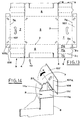
- Each of the heads 7 of the blank illustrated in Fig. 13 has articulated thereto, by a relative transversal creasing line 7a, a tab 107.
- Winglets 108 are articulated to the ends of the tab 107 by longitudinal creasing lines 107a situated on the level of the longitudinal creasing lines 2a.
- the tabs 107 are turned, in suitable time relation, inward (arrow K, Fig. 14) and the winglets 108 are turned downward until they match the upper parts R of the correspondent external flaps 11a.
- the winglets 108 and the aforementioned parts R are heated by suitable heating means (not shown).
- the heating can be carried out upstream of the final forming station 90 or in the region thereof.
- the proposed machine produces, in best way, box containers equipped with suitable stiffening angular elements, from a blank of synthetic resin.
- the box containers are produced without use of other materials, such as glue and the like, which results in considerable advantage for recycling, that becomes easy and convenient.
- An important feature of the machine is its high production capacity and small dimensions.
Landscapes
- Engineering & Computer Science (AREA)
- Mechanical Engineering (AREA)
- Chemical & Material Sciences (AREA)
- Combustion & Propulsion (AREA)
- Making Paper Articles (AREA)
- Lining Or Joining Of Plastics Or The Like (AREA)
- Auxiliary Devices For And Details Of Packaging Control (AREA)
Claims (7)
- Vorrichtung zur Herstellung von Verpackungsbehältern aus Zuschnitten (10) aus Kunstharz, wobei diese Zuschnitte gekennzeichnet sind durch:
longitudinal (2) und transversal (3) verlaufende Faltlinien, transversale Schlitze (4), die einen Boden (5) bilden, Seitenflächen (6) und Vorder- und Rückseitenabdeckungen (7) eines Vorratsbehälters (100) sowie vier Faltbereiche (9), die paarweise mit den genannten Abdeckungen (7) über longitudinale Faltlinien (2a) verbunden sind, wobei jeder Faltbereich (9) zwei longitudinale Faltlinien (2b, 2c) aufweist, die drei zusammenhängende Klappen (11a, 11b, 11c), und zwar eine innere, eine mittlere und eine äußere, bilden, wobei die genannte Vorrichtung folgendes umfaßt:dadurch gekennzeichnet, daß der genannte Heizkörper (61) ein Gehäuse (65) mit einem labyrinthartigen Pfad (66) umfaßt, durch den die zu erhitzende Luft geleitet wird und der einen Widerstandskörper (68) aufweist, durch den der genannte Luftstrom fließt.ein Magazin (12) für einen Stapel (P) von Zuschnitten (10);Greifmittel (13a, 13 b) zum periodischen Weitertransport eines Zuschnitts (10) vom Stapel (P) zu einer Entnahmestation (Z),Fördermittel (30, 40, 50), die die Zuschnitte (10) von der genannten Entnahmestation (Z) über wenigstens eine Zwischenstation (S1) zu einer abschließenden Formgebungsstation (90) transportieren;Handhabungsmittel (46), die an der genannten Zwischenstation (81) angeordnet sind und die die genannten Klappen (11a, 11b, 11c) der genannten Faltbereiche (9) entlang zugeordneter Faltlinien (2a, 2b, 2c) falten, wobei die genannten äußeren Klappen (11c) an die genannten zugeordneten Bereiche der Vorder- und Rückseitenabdeckungen (7) herangezogen werden, um auf diese Weise entsprechende rohrförmige Verstärkungselemente (20) zu bilden;eine Heizeinheit (60), die einen Heizkörper (61) umfaßt, die in der Zwischenstation (S1) angeordnet ist und die geeignet ist, einen Strom heißer Luft zu erzeugen und die Temperatur der äußeren Klappen (11c) der Faltbereiche (9) und der zugeordneten Bereiche der Vorder- und Rückseitenabdeckungen (7) des genannten Zuschnitts (10) auf einen vorgegebenen Wert zu erhöhen,Anpreßmittel (70), die die genannten äußeren Klappen (11c), die von den genannten Handhabungsmitteln (46) an die genannten zugeordneten Bereiche der Vorder- und Rückseitenabdeckungen (7) herangezogen sind, anpressen, um diese mittels Schmelzschweißen zu verbinden, - Vorrichtung gemäß Anspruch 1, dadurch gekennzeichnet, daß der genannte Heizkörper (61) mit einem röhrenförmigen Arm (62) mit wenigstens einem Paar Düsen (63, 64) verbunden ist, deren Form im wesentlichen der Form der zu erhitzenden Bereiche entspricht und aus denen der Luftstrom austritt
- Vorrichtung gemäß Anspruch 1, dadurch gekennzeichnet, daß die genannte erste Heizeinheit (60) jeweils einen Heizkörper (61) aufweist, der einen Strom heißer Luft erzeugt und der mit einem röhrenförmigen Arm (62) verbunden ist, der mit einem Düsenpaar (69) ausgestattet ist, das sich zu dessen beiden Seiten erstreckt und aus dem der vorgenannte Luftstrom austritt, um gleichzeitig die äußeren Klappen (11c) zu erhitzen, die derart gefaltet sind, daß sie an den Vorder- und Rückseitenabdeckungen (7) anliegen.
- Vorrichtung gemäß Anspruch 1, dadurch gekennzeichnet, daß sie eine zweite Heizeinheit (80) aufweist, die in einer zweiten Zwischenstation (S2) arbeitet, die stromabwärts der genannten ersten Zwischenstation (S1) angeordnet ist und die die Temperatur der inneren Klappen (11a) und der zugeordneten lateralen Bereiche der Seitenflächen (6) des genannten Zuschnitts (10) auf einen vorgegebenen Wert erhöht.
- Vorrichtung gemäß Anspruch 4, dadurch gekennzeichnet, daß die genannte zweite Heizeinheit (80) jeweils einen Heizkörper (81) aufweist, der einen Strom heißer Luft erzeugt und der mit einem röhrenförmigen Arm (82) verbunden ist, der mit einem Paar Düsen (83, 84) ausgestattet ist, die rechtwinklig zueinander angeordnet sind und aus denen der vorgenannte Luftstrom in den Bereich der jeweils zugeordneten, zuvor gefalteten inneren Klappe (11a) sowie in einen zugeordneten lateralen Bereich einer Seitenfläche (6) flach in bezug auf den Boden (5) des genannten Zuschnitts (10) austritt.
- Vorrichtung gemäß Anspruch 4, dadurch gekennzeichnet, daß die genannte zweite Heizeinheit (80) sich in Längsrichtung zwischen einer vorderen Arbeitsposition im Bereich einer abschließenden Formgebungsstation (90) und einer rückwärtigen Position bewegt, in der dieses Heizelement (80) von der genannten Station (90) getrennt ist, und daß das Heizelement (80) mit einem Paar Düsen (85, 86) ausgestattet ist, aus denen ein Luftstrom austritt und die rechtwinklig zueinander angeordnet sind, um die genannten zugeordneten, zuvor gefalteten inneren Klappen (11a) sowie einen zugeordneten lateralen Bereich der genannten Seitenfläche (6) zu erwärmen, die durch die Ansteuerung eines in der Station (90) arbeitenden Schiebers (91) an Anschlägen (95) zur Anlage gebracht werden.
- Vorrichtung gemäß Anspruch 1, dadurch gekennzeichnet, daß die genannten Anpreßmittel (70) mit einer Reihe von Rollen (71) ausgestattet sind, die auf den Zuschnitt (10) einwirken, wenn dieser den Bereich passiert.
Applications Claiming Priority (3)
| Application Number | Priority Date | Filing Date | Title |
|---|---|---|---|
| IT96BO000229A IT1285913B1 (it) | 1996-04-30 | 1996-04-30 | Macchina per la realizzazione di contenitori a cassetta di resina sintetica |
| ITBO960229 | 1996-04-30 | ||
| PCT/IB1997/000440 WO1997040977A1 (en) | 1996-04-30 | 1997-04-25 | Machine for producing box containers from blanks of synthetic resin |
Publications (2)
| Publication Number | Publication Date |
|---|---|
| EP0904193A1 EP0904193A1 (de) | 1999-03-31 |
| EP0904193B1 true EP0904193B1 (de) | 2001-07-25 |
Family
ID=11341365
Family Applications (1)
| Application Number | Title | Priority Date | Filing Date |
|---|---|---|---|
| EP97916593A Expired - Lifetime EP0904193B1 (de) | 1996-04-30 | 1997-04-25 | Vorrichtung zur herstellen von verpackungsbehältern aus zuschnitten aus kunstharz |
Country Status (5)
| Country | Link |
|---|---|
| EP (1) | EP0904193B1 (de) |
| DE (1) | DE69705836D1 (de) |
| ES (1) | ES2160939T3 (de) |
| IT (1) | IT1285913B1 (de) |
| WO (1) | WO1997040977A1 (de) |
Families Citing this family (4)
| Publication number | Priority date | Publication date | Assignee | Title |
|---|---|---|---|---|
| EP1302305A3 (de) * | 2001-10-09 | 2004-01-21 | Inpak Imola S.r.l. | Vorrichtung zur Herstellung Kastenförmiger Behälter aus Kunststoff |
| ES2285884B1 (es) * | 2004-12-15 | 2008-10-01 | Telesforo Gonzalez Olmos | Mecanismo perfeccionado para maquinas formadoras de cajas de carton. |
| ZA201108826B (en) * | 2011-12-01 | 2012-06-27 | Gossamer Machinery (Pty) Ltd | Method of erecting containers |
| IT201800005745A1 (it) * | 2018-05-28 | 2019-11-28 | Macchina formatrice di cassette di cartone, particolarmente del tipo portanti. |
Family Cites Families (6)
| Publication number | Priority date | Publication date | Assignee | Title |
|---|---|---|---|---|
| US2818484A (en) * | 1952-01-10 | 1957-12-31 | E G Staude Mfg Company Inc | Box welding apparatus |
| GB898960A (en) * | 1958-12-24 | 1962-06-14 | Technical Waxes Ltd | Improvements relating to the heat sealing of packages |
| US3801266A (en) * | 1973-03-15 | 1974-04-02 | Container Corp | Hot air diversion device |
| US4581005A (en) * | 1983-06-01 | 1986-04-08 | Moen Lenard E | Manufacture of boxes with integrally reinforced walls |
| IT1257785B (it) * | 1992-05-07 | 1996-02-13 | Studio Vame Srl | Macchina per la realizzazione di contenitori a cassetta di cartone o di materiali similari. |
| JP3222991B2 (ja) * | 1993-07-13 | 2001-10-29 | 大日本印刷株式会社 | 紙容器シール用加熱方法及び装置 |
-
1996
- 1996-04-30 IT IT96BO000229A patent/IT1285913B1/it active IP Right Grant
-
1997
- 1997-04-25 EP EP97916593A patent/EP0904193B1/de not_active Expired - Lifetime
- 1997-04-25 WO PCT/IB1997/000440 patent/WO1997040977A1/en not_active Ceased
- 1997-04-25 DE DE69705836T patent/DE69705836D1/de not_active Expired - Lifetime
- 1997-04-25 ES ES97916593T patent/ES2160939T3/es not_active Expired - Lifetime
Also Published As
| Publication number | Publication date |
|---|---|
| ITBO960229A0 (it) | 1996-04-30 |
| IT1285913B1 (it) | 1998-06-26 |
| ES2160939T3 (es) | 2001-11-16 |
| DE69705836D1 (de) | 2001-08-30 |
| EP0904193A1 (de) | 1999-03-31 |
| ITBO960229A1 (it) | 1997-10-30 |
| WO1997040977A1 (en) | 1997-11-06 |
Similar Documents
| Publication | Publication Date | Title |
|---|---|---|
| AU719745B2 (en) | Flat-top container with an opening fitment | |
| US5267934A (en) | Carton pour spout fitment applicator | |
| US3956975A (en) | Packaging method and apparatus | |
| US5867966A (en) | Method and apparatus for forming the top of a container | |
| JPH0399838A (ja) | 容器成形装置 | |
| AU685679B2 (en) | Apparatus and method for sealing gabled containers | |
| WO2000029293A1 (en) | Method and apparatus for forming the top of a container with a fitment thereon | |
| US5829228A (en) | Method and apparatus for forming the top of a container | |
| US5809743A (en) | Top folding and sealing apparatus for forming and sealing the fin of a gabled carton | |
| RU2318669C2 (ru) | Способ и установка для формования контейнеров, в частности контейнеров для пищевых продуктов | |
| US3303761A (en) | Machine for forming, filling, closing and sealing plastic coated paperboard containers | |
| EP1091874B1 (de) | Verfahren und verpackungsmaschine zum formen von behältern | |
| AU694556B2 (en) | Carton transporting apparatus and method | |
| EP0904193B1 (de) | Vorrichtung zur herstellen von verpackungsbehältern aus zuschnitten aus kunstharz | |
| US3535987A (en) | Apparatus and method for forming cartons | |
| GB1079150A (en) | Apparatus and method for folding and sealing cartons | |
| RU2321495C2 (ru) | Система для формования контейнеров, в особенности контейнеров для пищевых продуктов | |
| EP0466271B1 (de) | Vorrichtung zum Verkleben der oberen Teile eines Behälters | |
| US4189986A (en) | Method and apparatus for heat sealing a package blank | |
| CN100457438C (zh) | 封装装置 | |
| JPH0592109U (ja) | 包装容器の形式の物品を搬送する装置 | |
| US3709114A (en) | Container forming machine | |
| EP4628412A1 (de) | Füllmaschine zum füllen von nahrungsmittelprodukten in verpackungskörper aus kartonagen oder staubpartikeln | |
| JP7500620B2 (ja) | 傾斜ゲーブルを有する包装体のゲーブル面を後成形するためのデバイスおよび方法 | |
| WO2007071698A1 (en) | Improvements in or relating to packaging |
Legal Events
| Date | Code | Title | Description |
|---|---|---|---|
| PUAI | Public reference made under article 153(3) epc to a published international application that has entered the european phase |
Free format text: ORIGINAL CODE: 0009012 |
|
| 17P | Request for examination filed |
Effective date: 19981117 |
|
| AK | Designated contracting states |
Kind code of ref document: A1 Designated state(s): DE ES FR NL |
|
| 17Q | First examination report despatched |
Effective date: 19990401 |
|
| GRAG | Despatch of communication of intention to grant |
Free format text: ORIGINAL CODE: EPIDOS AGRA |
|
| GRAG | Despatch of communication of intention to grant |
Free format text: ORIGINAL CODE: EPIDOS AGRA |
|
| GRAH | Despatch of communication of intention to grant a patent |
Free format text: ORIGINAL CODE: EPIDOS IGRA |
|
| GRAH | Despatch of communication of intention to grant a patent |
Free format text: ORIGINAL CODE: EPIDOS IGRA |
|
| GRAA | (expected) grant |
Free format text: ORIGINAL CODE: 0009210 |
|
| AK | Designated contracting states |
Kind code of ref document: B1 Designated state(s): DE ES FR NL |
|
| PG25 | Lapsed in a contracting state [announced via postgrant information from national office to epo] |
Ref country code: NL Free format text: LAPSE BECAUSE OF FAILURE TO SUBMIT A TRANSLATION OF THE DESCRIPTION OR TO PAY THE FEE WITHIN THE PRESCRIBED TIME-LIMIT Effective date: 20010725 |
|
| REF | Corresponds to: |
Ref document number: 69705836 Country of ref document: DE Date of ref document: 20010830 |
|
| PG25 | Lapsed in a contracting state [announced via postgrant information from national office to epo] |
Ref country code: DE Free format text: LAPSE BECAUSE OF FAILURE TO SUBMIT A TRANSLATION OF THE DESCRIPTION OR TO PAY THE FEE WITHIN THE PRESCRIBED TIME-LIMIT Effective date: 20011026 |
|
| REG | Reference to a national code |
Ref country code: ES Ref legal event code: FG2A Ref document number: 2160939 Country of ref document: ES Kind code of ref document: T3 |
|
| ET | Fr: translation filed | ||
| NLV1 | Nl: lapsed or annulled due to failure to fulfill the requirements of art. 29p and 29m of the patents act | ||
| PG25 | Lapsed in a contracting state [announced via postgrant information from national office to epo] |
Ref country code: ES Free format text: LAPSE BECAUSE OF NON-PAYMENT OF DUE FEES Effective date: 20020426 |
|
| PLBE | No opposition filed within time limit |
Free format text: ORIGINAL CODE: 0009261 |
|
| STAA | Information on the status of an ep patent application or granted ep patent |
Free format text: STATUS: NO OPPOSITION FILED WITHIN TIME LIMIT |
|
| 26N | No opposition filed | ||
| PG25 | Lapsed in a contracting state [announced via postgrant information from national office to epo] |
Ref country code: FR Free format text: LAPSE BECAUSE OF NON-PAYMENT OF DUE FEES Effective date: 20021231 |
|
| REG | Reference to a national code |
Ref country code: FR Ref legal event code: ST |
|
| REG | Reference to a national code |
Ref country code: ES Ref legal event code: FD2A Effective date: 20030514 |