EP0904200B1 - Cylindre porte-plaque dote d'un dispositif tendeur fixe de montage de plaque - Google Patents
Cylindre porte-plaque dote d'un dispositif tendeur fixe de montage de plaque Download PDFInfo
- Publication number
- EP0904200B1 EP0904200B1 EP97921739A EP97921739A EP0904200B1 EP 0904200 B1 EP0904200 B1 EP 0904200B1 EP 97921739 A EP97921739 A EP 97921739A EP 97921739 A EP97921739 A EP 97921739A EP 0904200 B1 EP0904200 B1 EP 0904200B1
- Authority
- EP
- European Patent Office
- Prior art keywords
- plate
- printing plate
- printing
- cylinder
- plate cylinder
- Prior art date
- Legal status (The legal status is an assumption and is not a legal conclusion. Google has not performed a legal analysis and makes no representation as to the accuracy of the status listed.)
- Expired - Lifetime
Links
Images


Classifications
-
- B—PERFORMING OPERATIONS; TRANSPORTING
- B41—PRINTING; LINING MACHINES; TYPEWRITERS; STAMPS
- B41F—PRINTING MACHINES OR PRESSES
- B41F27/00—Devices for attaching printing elements or formes to supports
- B41F27/12—Devices for attaching printing elements or formes to supports for attaching flexible printing formes
- B41F27/1281—Devices for attaching printing elements or formes to supports for attaching flexible printing formes details of the printing plate ends
Definitions
- the present invention relates to printing presses, and more particularly, to printing plates and mechanisms for mounting printing plates onto plate cylinders of printing presses.
- Printing elements for offset printing presses have traditionally been formed as flat plates which are mounted within an axially extending gap in a plate cylinder.
- a plate lock-up mechanism such as a reel-rod mechanism
- Typical reel-rod mechanisms require a relatively large gap in the cylinder which causes vibrations and print defects during printing.
- reel-rod mechanisms do not provide uniform tensioning across the width of the printing plate. Non-uniform tensioning, in turn, may cause the printing plate to crack prematurely.
- EP 0 199 520 A2 describes a gravure printing press having a plate cylinder on which a gravure printing plate is fastened by means of magnetic inserts.
- the gravure printing plate comprises a straight or even trailing end portion which is received in a recess formed in the leading end portion, so as to provide for an even surface of the gravure cylinder during the printing operation, in which the cylinder is in contact with a doctor blade.
- it is suggested to fill the gap between the trailing end portion and an adjoining bend adjacent the recessed portion of the leading end of the printing plate with an adhesive filler material, in order to obtain a completely even surface of the plate cylinder.
- the document does not suggest to bond the trailing end to the recessed portion formed at the leading end of the printing plate.
- DE 44 12 873 A1 describes a sleeve-shaped printing plate for a web-fed rotary printing press, which is manufactured by welding together the straight end portions of the trailing end and the leading end of a conventional printing plate. A part of the welding seam projects towards the center of the sleeve and is received in a corresponding notch formed in the circumferential surface of the plate cylinder when axially sliding the sleeve-shaped printing plate onto the plate cylinder body. Due to the high temperature of the welding operation, the plate material in the region of the welding seam is weakened and is likely to crack when operating the printing press. Moreover, the welding of the printing plate requires sophisticated and expensive equipment in order to provide for a precise register of the printed image.
- U. S. Patent No. 5,284,093 to Guaraldi describes a plate lock-up mechanism which allows the use of a particularly narrow plate cylinder gap. This reduction in the size of the gap in the plate cylinder reduces vibrations and print defects. In addition, since this plate lock-up mechanism applies very little tension to the printing plate, the likelihood of plate cracking is reduced. However, this plate lock-up mechanism utilizes a complicated mechanical mounting system.
- a system for axially mounting a flat printing plate over a plate cylinder while providing uniform tensioning of the printing plate during installation and removal of the printing plate, and during printing.
- a printing unit of a printing press includes a blanket cylinder and a plate cylinder, the plate cylinder having an axially extending slot therein. A recess is provided along the axially extending slot.
- the plate cylinder has a plurality of apertures arranged on its outer surface, the apertures being connected to a source of pressurized fluid such as an air compressor.
- a printing plate has an outer surface and an inner surface, the outer surface for receiving an image to be transferred to a printing blanket.
- the printing plate also includes a lead end and a tail end.
- a first bend and a second bend form opposing angles at a first distance from the lead end of the printing plate, and a third bend forms an opposing angle relative to the second bend at a second distance from the lead end.
- a recessed portion is thereby formed between the second bend and the third bend, and an angular end portion is formed between the third bend and the lead end.
- the second distance is less than or equal to the depth of the axially extending slot.
- the first distance is approximately equal to the second distance plus the width of the recess of the plate cylinder.
- the tail end of the printing plate is bonded to the recessed portion by welding or with an adhesive.
- the source of pressurized fluid is engaged to supply pressurized fluid (e.g. air, another gas, or liquid) through the apertures of the plate cylinder.
- pressurized fluid e.g. air, another gas, or liquid
- a press operator mounts an end of the printing plate onto the plate cylinder, aligning the angular end portion of the printing plate with the slot in the plate cylinder.
- the pressurized fluid effects a radial expansion of the printing plate so that the printing plate can be slid axially over the plate cylinder.
- the source of pressurized fluid is disengaged, and the printing plate contracts and is securely fixed to the plate cylinder.
- the angular end portion of the printing plate is disposed within the slot of the plate cylinder, there will be no slippage between the plate cylinder and printing plate during printing.
- a T-shaped bonding plate is provided, and the inner surface of the lead end and tail end of the printing plate are bonded to the bonding plate by welding or with an adhesive.
- the source of pressurized fluid is engaged to supply pressurized fluid (e.g. air, another gas, or liquid) through the apertures of the plate cylinder.
- pressurized fluid e.g. air, another gas, or liquid
- a press operator mounts an end of the printing plate onto the plate cylinder, aligning the bonding plate with the recess and slot in the plate cylinder.
- the pressurized fluid effects a radial expansion of the printing plate so that the printing plate can be slid axially over the plate cylinder.
- the source of pressurized fluid is disengaged, and the printing plate contracts and is securely fixed to the plate cylinder.
- the bonding plate is disposed within the axial slot of the plate cylinder, there will be no slippage between the plate cylinder and printing plate during printing.
- Fig. 1 shows an offset printing press in accordance with the present invention.
- Fig. 2 shows a printing plate
- Fig. 3 shows a plate cylinder in accordance with a first embodiment of the present invention.
- Figs. 4(a-c) show the printing plate of Fig. 2 mounted on a plate cylinder in accordance with the first embodiment of the present invention.
- Fig. 5 shows the printing plate of Fig. 2 mounted on a plate cylinder in accordance with a second embodiment of the present invention
- Figs. 6(a,b) show a prior art reel-rod mechanism, and the forces resulting from mounting a printing plate onto a plate cylinder with the reel-rod mechanism.
- Figs 6(c,d) illustrate the forces resulting from mounting a printing plate onto a plate cylinder in accordance with the present invention.
- Fig. 7(a) shows a mounting mandrel in accordance with the present invention.
- Fig. 7(b) illustrates the manner in which the printing plate of Fig. 2 is mounted onto the mounting mandrel of Fig. 7(a).
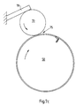
- Fig. 7(c) illustrates a method of forming an axially removable printing plate in accordance with the present invention.
- Fig. 7(d) shows a further embodiment of the mounting mandrel.
- Fig. 1 shows a printing press 100 including a plate cylinder 1 and a blanket cylinder 2 rotatably mounted within a frame 3.
- a printing plate 30 is formed as a flat sheet having a lead end 40 and a tail end 47. An image to be printed is exposed on one side of the plate 30.
- Fig. 3 shows the plate cylinder 1 in more detail.
- the plate cylinder 1 includes a plurality of apertures 10 along the outer surface 9 of the cylinder 1.
- the apertures 10 are coupled to a source of pressurized fluid 49 (e.g., an air compressor) as shown in Fig. 1.
- the plate cylinder 1 includes an axial slot 20 for receiving the lead end 40 of the printing plate 30 as described below.
- An axial recess 11 is provided adjacent to the slot 20.
- Fig. 4(a) shows the printing plate 30 mounted on the plate cylinder 1 in accordance with a first embodiment of the present invention. As illustrated, three bends have been made in the lead end 40 of the plate 30. A first bend 31 and an opposing second bend 32 form an overlap joint. These bends 31, 32 form a recessed portion 35 of the printing plate which rests in the axial recess 11 of the plate cylinder 1. A third bend 33 forms an angular end portion 36 of the printing plate which rests in the slot 20 of the plate cylinder 10.
- the tail end 47 of the printing plate is bonded to the recessed portion 35 by welding or with a suitable adhesive, such as, for example, an epoxy or a quick setting cyanacrylate ester.
- the recessed portion 35 is constructed so that when the tail end 47 is adhered to the portion 35, the tail end 47 is approximately the same height as the adjacent portion 38 of the lead end 40.
- the slot 20 could, for example, have a width of 0,033cm (0.013 inches) and a depth of 0,318cm (0.125 inches).
- the tail end 47 is beveled as illustrated in Fig. 4b to further reduce the size of the gap.
- the smaller gap of Figs. 4(a,b) results in a reduction in bounce disturbances as compared to conventional gapped plate cylinders.
- the plate mounting system according to the present invention is not subject to the print defects resulting from slippage between the printing plate and the plate cylinder.
- the slot 20 in the plate cylinder 1 extends perpendicularly from the axial recess 11.
- the slot 20 may be formed at an acute angle ⁇ 36 relative to the axial recess 11 of the plate cylinder, and the angular end portion may likewise form an angle ⁇ 36 relative to the recessed portion 35 of the printing plate.
- the lead end and tail end (40,47) of the printing plate 30 are bonded to a T-shaped bonding plate 80.
- the bonding plate 80 is preferably made of the same material as the printing plate 30.
- the lead and tail ends of the printing plate can be bonded to the bonding plate with an adhesive or by welding. Examples of suitable welding techniques include TIG, Resistance Seam, and Electron Beam welding.
- the lead end 40 abuts the tail end 47 as shown in Fig. 5 in order to minimize the gap in the surface of the printing plate 30.
- the printing plate is mounted axially over the plate cylinder with pressurized fluid in the manner described above with regard to Figs. 1 through 4.
- the bonding plate 80 rests within the axial recess 11' and slot 20' of the plate cylinder 1'. As a result, the printing plate 30 will not slip relative to the plate cylinder during printing.
- a rectangular shaped bonding plate could be employed in combination with a plate cylinder with a deeper recess, with the recess impeding slippage of the printing plate.
- Figs. 6a,b show a prior art reel-rod lock-up arrangement for a plate cylinder 180.
- a bend is made in the lead end 140 and in the tail end 147 of the printing plate 150.
- the lead end 140 is hooked onto a first side of a plate cylinder gap 170, and the printing plate 30 is wrapped circumferentially around the plate cylinder by a clockwise rotation of the plate cylinder 180.
- the tail end 147 of the printing plate is then inserted through the plate cylinder gap 170 and into an axial gap 200 in a reel-rod 220.
- the reel-rod 220 rotates counter-clockwise as shown, thereby securing the printing plate 30 to the plate cylinder.
- reel-rod lock-ups As discussed above, a disadvantage of reel-rod lock-ups is that they result in non-uniform forces being applied to the printing plate. These non-uniform forces, in turn, increase the likelihood of plate cracking, and may cause the plate to slip out of the end portions of the reel-rod 220.
- the reel-rod 220 As the reel-rod 220 is rotated, it applies a force F L to the tail end of the printing plate. However, since the reel-rod 220 can only be twisted at each end, the force applied at the center of the reel-rod 220 is less than the force applied at the ends due to the torsional deflection of the reel-rod 220. In addition, the direction of the resultant force applied at the tail end of the printing plate (Fp tail ) is different than the direction of the force Tp which is needed to hold the printing plate 150 onto the plate cylinder 180. Only a portion of the available force at the reel-rod (F L ) is applied as the force Fp tail due to frictional losses.
- the printing plate is mounted axially over the plate cylinder while in a radially expanded state.
- the radial pressure of the compressed air creates a uniform reactionary force Tp'+, which is slightly greater than Tp', throughout the plate in the circumferential direction during installation.
- Tp' is slightly greater than Tp'
- this construction applies less force at the tail ends of the plate than the force Fp cail of prior art reel-rod arrangements, but is capable of applying a force Tp' which is greater than the force Tp of prior art reel-rod arrangements. Moreover, the force Tp' is applied in a uniform manner across the entire plate. As a result, this construction reduces the likelihood of plate cracking.
- each blanket cylinder 2 includes a plurality of apertures 10 along the outer surface of the blanket cylinder 2 as shown in Fig. 1.
- the apertures 10 are coupled to the source of compressed fluid 49.
- a tubular printing blanket 70 is mounted axially over the blanket cylinder. Examples of suitable tubular printing blankets are described in U.S. Patent Nos. 5,304,267, 5,323,702, and 5,429,048. While only a single side frame 3 is shown supporting one end of the cylinders 1, 2 in Fig. 1, it should be understood that a second side frame (not shown) may be provided to support the other end of the cylinders 1,2. In such a configuration, openings are provided in the second side-frame to allow installation and removal of the plates 30 and blankets 70.
- Figs 7(a-d) show a mounting mandrel 50 in accordance with a further embodiment of the present invention.
- the mounting mandrel 50 has a conical section 51 and a cylindrical section 52.
- a mandrel slot 53 is disposed axially across the cylindrical section 52.
- a mandrel recess 54 is disposed adjacent to the mandrel slot 53.
- a conventional three roll sheet bender is used to prebend the printing plate 30 into a cylindrical shape. Then, an operator grasps the lead end 40 and the tail end 47 of the printing plate 30 and slides the printing plate axially over the conical section 51 of the as shown in Figure 7b.
- the bends 31, 32, 33 in the plate 30 may be formed using a stamping process. Then, the plate 30 is fed through a three roll sheet bender to form the plate 30 into a cylindrical shape. The printing plate 30 is then slid axially over the mounting mandrel, and the angular end portion 36 of the plate is slid into the mandrel slot 53. Referring to Fig. 7(c), a rubber covered top pressure roller 70 is then lowered into contact with the plate 30 on the mounting mandrel 50 so that the pressure roller 70 and the mounting mandrel 50 are in rolling engagement at a nip 75.
- Tension between the pressure roller 70 and mounting mandrel 50 is maintained by a tensioning device 79.
- the tensioning device 79 can be of any known construction.
- the tensioning device 79 could be a block of wood which rests on top of the pressure roller 70.
- the mounting mandrel 50 As the mounting mandrel 50 rotates clockwise, it drives the pressure roller 70 rotates counter-clockwise through friction. The tensioning device 79 resists this movement, causing the pressure roller 70 to apply tension to the plate 30, tightly wrapping the plate 30 around the mounting mandrel 50. Then, an adhesive is applied to the recessed portion 35 just before the recessed portion 35 enters the nip 75 between the mounting mandrel 50 and pressure roller 70. As the mounting mandrel 50 and pressure roller 70 continue to rotate, the tail end 47 of the printing plate is bonded to the recessed portion 35. Once the tail end 47 is bonded to the recessed portion 35, the printing plate can be removed from the mounting mandrel and mounted onto the plate cylinder 1. Since the diameter of the mounting mandrel is slightly smaller than the diameter of the plate cylinder, an interference fit will be created when the plate is mounted on the plate cylinder.
- the bonding plate 80 is bonded to a first end of the printing plate. Then, the plate 30 is fed through the three roll sheet bender to form the plate into a cylindrical shape. The printing plate is then slid axially over the mounting mandrel, and the bonding plate 80 is slid into the mandrel recess 54. The rubber covered top pressure roller is then lowered into contact with the plate on the mounting mandrel so that the pressure roller and the mounting mandrel are in rolling engagement. As the mounting mandrel rotates clockwise, and the pressure roller rotates counter-clockwise, the plate is tightly wrapped around the mounting mandrel.
- an adhesive is applied to the exposed half of the bonding plate 80 just before the bonding plate 80 enters the nip between the mounting mandrel and pressure roller. As the mounting mandrel and pressure roller continue to rotate, the second end of the printing plate is bonded to the bonding plate 80. Once the second is bonded to the bonding plate 80, the printing plate can be removed from the mounting mandrel and mounted onto the plate cylinder 1.
- the conical section 51 serves to gradually shape the printing plate to the diameter of the cylindrical section 52 of the mounting mandrel as the plate is slid axially over the conical section 51 and cylindrical section 52 as shown in Fig. 7(b).
- the mounting mandrel 50 may be used to position the plate 30 relative to the plate cylinder 1 in order to facilitate installation of the plate 30 onto the plate cylinder 1.
- the mandrel 50 may be mounted on a positioning platform 60.
- the positioning platform 60 may further include a positioning arm 61 for aligning the mandrel 50 with the plate cylinder 1.
- the positioning arm 61 may be configured to allow the vertical and circumferential position of the mandrel 50 to be set.
- the plate 30 can be slid off of the mandrel 50 and onto the plate cylinder 1 as illustrated by the dashed lines in Fig. 7(d).
- the circumferential and vertical position of the mandrel 50 could be adjusted manually, for example, with clamps 80. Alternatively, it could be controlled with hydraulic or pneumatic pistons, or in any other known manner.
- mounting mandrel 50 need not be used in combination with the fixed tensioning printing plate 30, but could also be used with other plate mounting systems.
- the fixed tensioning printing plate 30 need not be used in conjunction with the mounting mandrel 50.
Landscapes
- Engineering & Computer Science (AREA)
- Mechanical Engineering (AREA)
- Supply, Installation And Extraction Of Printed Sheets Or Plates (AREA)
Claims (10)
- Procédé pour monter axialement une plaque d'impression plate sur un cylindre porte-plaque comprenant les phases consistant à :former des premier et deuxième plis opposés à une première distance d'une extrémité de tête d'une plaque d'impression ;

- Procédé selon la revendication 1, dans lequel la portion d'extrémité coudée est perpendiculaire à la portion en retrait.
- Procédé selon la revendication 1, dans lequel la portion d'extrémité coudée forme un angle aigu avec la portion en retrait.
- Procédé selon l'une des revendications 1 à 3, caractérisé en ce que la plaque d'impression est assemblée à la portion en retrait par soudage ou à l'aide d'un adhésif approprié.
- Procédé selon l'une des revendications 1 à 4, comprenant en outre la phase consistant à glisser la plaque d'impression axialement sur un mandrin de montage de forme conique avant la phase d'assemblage.
- Mandrin de montage pour la mise en oeuvre du procédé selon la revendication 5, comprenant une première portion (52) de forme cylindrique ayant une surface extérieure, une première et une deuxième extrémités, et une fente axiale (53) disposée le long de la surface extérieure et destinée à recevoir une extrémité de la plaque d'impression (30) ; et une deuxième portion (51) de forme conique reliée à la première extrémité de la première portion (52) de forme cylindrique, la deuxième portion (51) de forme conique recevant axialement la plaque d'impression (30) et remettant la plaque d'impression (30) en forme avant qu'elle ne soit glissée sur la première portion (52) de forme cylindrique.
- Mandrin de montage selon la revendication 6, comprenant en outre un retrait axial (54) disposé adjacent à la fente axiale (53) le long de la surface extérieure de la première portion cylindrique (52).
- Mandrin de montage selon la revendication 6, comprenant en outre un bras de positionnement (61) relié à la deuxième extrémité de la première portion (52) de forme cylindrique, le bras de positionnement (61) déterminant la hauteur et la position circonférentielle de la première portion (52) de forme cylindrique.
- Mandrin de montage selon la revendication 8, comprenant en outre une portion de base mobile (60) reliée au bras de positionnement (61), la portion de base mobile (60) et le bras de positionnement (61) supportant la première portion (52) de forme cylindrique et la deuxième portion (51) de forme conique, la portion de base mobile (60) déterminant la position latérale du mandrin de montage (50).
- Mandrin de montage selon l'une des revendications 6 à 9, caractérisé en ce que la plaque d'impression est une plaque d'impression utilisée dans une presse à imprimer lithographique offset.
Applications Claiming Priority (3)
| Application Number | Priority Date | Filing Date | Title |
|---|---|---|---|
| US08/639,135 US5687647A (en) | 1996-04-26 | 1996-04-26 | Plate cylinder with fixed tensioning plate mounting device |
| US639135 | 1996-04-29 | ||
| PCT/EP1997/002094 WO1997040986A1 (fr) | 1996-04-26 | 1997-04-24 | Cylindre porte-plaque dote d'un dispositif tendeur fixe de montage de plaque |
Publications (2)
| Publication Number | Publication Date |
|---|---|
| EP0904200A1 EP0904200A1 (fr) | 1999-03-31 |
| EP0904200B1 true EP0904200B1 (fr) | 2001-07-18 |
Family
ID=24562874
Family Applications (1)
| Application Number | Title | Priority Date | Filing Date |
|---|---|---|---|
| EP97921739A Expired - Lifetime EP0904200B1 (fr) | 1996-04-26 | 1997-04-24 | Cylindre porte-plaque dote d'un dispositif tendeur fixe de montage de plaque |
Country Status (6)
| Country | Link |
|---|---|
| US (1) | US5687647A (fr) |
| EP (1) | EP0904200B1 (fr) |
| JP (1) | JP2000508983A (fr) |
| CA (1) | CA2248655A1 (fr) |
| DE (1) | DE69705717T2 (fr) |
| WO (1) | WO1997040986A1 (fr) |
Families Citing this family (21)
| Publication number | Priority date | Publication date | Assignee | Title |
|---|---|---|---|---|
| DE19636412C1 (de) * | 1996-09-07 | 1998-01-08 | Koenig & Bauer Albert Ag | Zylinder |
| DE19844560C2 (de) * | 1998-09-29 | 2001-05-17 | Roland Man Druckmasch | Vorrichtung und Verfahren zum Befestigen einer flexiblen Druckform |
| JP2979315B1 (ja) * | 1998-11-26 | 1999-11-15 | 株式会社東京機械製作所 | 印刷版及びこの印刷版を装着する版胴 |
| DE10049283A1 (de) * | 2000-10-05 | 2002-04-11 | Hueck Folien Gmbh & Co Kg | Verfahren und Vorrichtung zur Herstellung einer zylindrischen Prägeform |
| DE10049576B4 (de) * | 2000-10-06 | 2014-07-24 | Manroland Web Systems Gmbh | Einrichtung zur Herstellung von Druckformen |
| DE102004013552A1 (de) * | 2004-03-19 | 2005-10-06 | Goss International Montataire S.A. | Aufzughülse für einen Zylinder in einer Druckmaschine |
| US20070125652A1 (en) * | 2005-12-02 | 2007-06-07 | Buckley Paul W | Electroform, methods of making electroforms, and products made from electroforms |
| US20070126148A1 (en) * | 2005-12-02 | 2007-06-07 | General Electric Company | Microstructured embossing drum and articles made therefrom |
| US20070125651A1 (en) * | 2005-12-02 | 2007-06-07 | Buckley Paul W | Electroform, methods of making electroforms, and products made from electroforms |
| US20070126144A1 (en) * | 2005-12-02 | 2007-06-07 | Yadong Jin | Polish/texture thermoplastic film and method for making the same |
| US20070125655A1 (en) * | 2005-12-02 | 2007-06-07 | Buckley Paul W | Electroform, methods of making electroforms, and products made from electroforms |
| US20070125653A1 (en) * | 2005-12-02 | 2007-06-07 | Coyle Dennis J | Multilayer electroform, methods of making multilayer electroforms, and products made therefrom |
| US20070125654A1 (en) * | 2005-12-02 | 2007-06-07 | Buckley Paul W | Electroform, methods of making electroforms, and products made from electroforms |
| US20070125248A1 (en) * | 2005-12-02 | 2007-06-07 | Coyle Dennis J | Embossing drum system with removable outer sleeve and methods of use |
| JP2009285861A (ja) * | 2008-05-27 | 2009-12-10 | Masayuki Izume | 印刷機用版および印刷機 |
| JP4925470B2 (ja) * | 2008-07-01 | 2012-04-25 | 雅幸 井爪 | 印刷機用版製造装置 |
| JP4925471B2 (ja) | 2008-08-11 | 2012-04-25 | 雅幸 井爪 | 印刷機用版装着装置および印刷機 |
| JP5500863B2 (ja) * | 2009-04-24 | 2014-05-21 | 昭和アルミニウム缶株式会社 | 印刷用版の装着装置、印刷機および印刷システム |
| KR20120130517A (ko) * | 2011-05-23 | 2012-12-03 | 삼성디스플레이 주식회사 | 러빙 장치 |
| JP5501486B2 (ja) * | 2013-01-11 | 2014-05-21 | 昭和アルミニウム缶株式会社 | 印刷方法、印刷用版の製造方法および印刷用版 |
| US20220168868A1 (en) * | 2020-12-01 | 2022-06-02 | Fortune Extendables Corp. | Abrasive wheel which can be provided with a sandpaper |
Family Cites Families (25)
| Publication number | Priority date | Publication date | Assignee | Title |
|---|---|---|---|---|
| US1963745A (en) * | 1932-07-05 | 1934-06-19 | Ingersoll Steel And Disc Co | Process of making composite metal articles |
| US2375603A (en) * | 1941-12-26 | 1945-05-08 | Moore Business Forms Inc | Cylinder for printing presses |
| GB578777A (en) * | 1942-05-11 | 1946-07-11 | Interchem Corp | Improvements in or relating to rotogravure printing members and method of making the same |
| US2869966A (en) * | 1952-06-06 | 1959-01-20 | E R Chilcott | Recording sheet and means for mounting same on a rotary drum |
| US3187542A (en) * | 1959-11-12 | 1965-06-08 | American Type Founders Co Inc | Bending apparatus for printing plates |
| US3146709A (en) * | 1962-04-09 | 1964-09-01 | West Essex Printing Plate Inc | Method and apparatus for mounting printing sleeves |
| JPS57107843A (en) * | 1980-12-26 | 1982-07-05 | Dainippon Printing Co Ltd | Attaching method of sleeve plate to printing roll in gravure printing and printing roll |
| US4495865A (en) * | 1983-03-15 | 1985-01-29 | Komori Printing Machinery Co., Ltd. | Plate clamping device of web-fed rotary printing press |
| EP0142874B1 (fr) * | 1983-11-14 | 1988-04-27 | De La Rue Giori S.A. | Cylindre d'impression avec dispositif de fixation des clichés en creux, pour rotatives |
| EP0199520A3 (fr) * | 1985-04-19 | 1989-02-08 | Vickers Plc | Presse d'impression en creux et sa méthode de fabrication |
| EP0211450B1 (fr) * | 1985-07-26 | 1989-05-24 | De La Rue Giori S.A. | Procédé et installation de fixation de plaques d'impression sur un cylindre porte-plaques |
| DE3702889A1 (de) * | 1987-01-31 | 1988-08-11 | Roland Man Druckmasch | Vorrichtung zum aufbringen einer huelse auf einen druckwerkzylinder |
| US4833986A (en) * | 1987-03-05 | 1989-05-30 | M.A.N. Roland Druckmaschinen Ag | Holding and tensioning system for a cover layer on a printing machine cylinder |
| DE3715536A1 (de) * | 1987-05-09 | 1988-12-01 | Roland Man Druckmasch | Lagerung fuer einen druckwerkzylinder |
| JPS63293058A (ja) * | 1987-05-25 | 1988-11-30 | Mitsubishi Paper Mills Ltd | オフセット輪転印刷機用版曲軸及びそれを用いた刷版装着方法 |
| IT1231223B (it) * | 1987-09-11 | 1991-11-26 | Cerutti Spa Off Mec | Metodo per giuntare le estremita' di una lastra per la stampa rotativa e giunzione cosi' ottenuta |
| US4932324A (en) * | 1988-06-06 | 1990-06-12 | Day International Corporation | Mounting device for adhesive-backed blankets |
| DE3934334C1 (fr) * | 1989-10-14 | 1991-04-11 | Heidelberger Druckmaschinen Ag, 6900 Heidelberg, De | |
| DE9002111U1 (de) * | 1990-02-22 | 1990-04-19 | MAN Roland Druckmaschinen AG, 6050 Offenbach | Füllstück für den Einsatz in die Grube eines Druckwerkzylinders in einer Rollenrotationsdruckmaschine |
| DE4140768C2 (de) * | 1991-12-11 | 1994-08-18 | Roland Man Druckmasch | Offset-Druckform |
| US5245924A (en) * | 1992-09-18 | 1993-09-21 | Rockwell International Corporation | Locking and adjusting device for a printing press |
| DE4315996C1 (de) * | 1993-05-13 | 1994-08-04 | Roland Man Druckmasch | Registereinrichtung für eine hülsenförmige Offset-Druckform |
| DE4412873C2 (de) * | 1993-05-13 | 1995-06-22 | Roland Man Druckmasch | Registereinrichtung für eine hülsenförmige Offset-Druckform |
| DE4404758C2 (de) * | 1994-02-15 | 1996-06-27 | Roland Man Druckmasch | Verfahren und Vorrichtung zum Wechseln der Bespannung eines Zylinders einer Rollenrotationsdruckmaschine |
| FR2720975B1 (fr) * | 1994-06-08 | 1996-07-19 | Martin Sa | Dispositif d'accrochage de clichés flexibles sur un cylindre d'impression. |
-
1996
- 1996-04-26 US US08/639,135 patent/US5687647A/en not_active Expired - Lifetime
-
1997
- 1997-04-24 EP EP97921739A patent/EP0904200B1/fr not_active Expired - Lifetime
- 1997-04-24 WO PCT/EP1997/002094 patent/WO1997040986A1/fr not_active Ceased
- 1997-04-24 CA CA002248655A patent/CA2248655A1/fr not_active Abandoned
- 1997-04-24 JP JP09538561A patent/JP2000508983A/ja not_active Ceased
- 1997-04-24 DE DE69705717T patent/DE69705717T2/de not_active Expired - Lifetime
Also Published As
| Publication number | Publication date |
|---|---|
| DE69705717D1 (de) | 2001-08-23 |
| EP0904200A1 (fr) | 1999-03-31 |
| US5687647A (en) | 1997-11-18 |
| CA2248655A1 (fr) | 1997-11-06 |
| JP2000508983A (ja) | 2000-07-18 |
| WO1997040986A1 (fr) | 1997-11-06 |
| DE69705717T2 (de) | 2002-12-05 |
Similar Documents
| Publication | Publication Date | Title |
|---|---|---|
| EP0904200B1 (fr) | Cylindre porte-plaque dote d'un dispositif tendeur fixe de montage de plaque | |
| JP5638166B2 (ja) | 版胴と版胴に配置された少なくとも1枚の刷版とを備える装置 | |
| JP5570676B1 (ja) | 版胴に刷版を配置する方法 | |
| US5351615A (en) | Offset blanket for a grooveless blanket cylinder composed of a carrier plate and a rubber layer placed thereon | |
| US6357354B1 (en) | Method and apparatus for fitting a printing plate to a plate cylinder | |
| JP2956021B2 (ja) | 印刷機の版胴に版板を張設するための装置 | |
| US7966933B2 (en) | Apparatus and method for clamping printing plates on a plate cylinder | |
| US9387665B2 (en) | In-register arrangement of printing plates on printing-press cylinders with a temperature-control system | |
| JP2001353846A (ja) | マルチプレート式版胴を備えた印刷機 | |
| JP6086974B2 (ja) | クランプ装置を備えた印刷機の版胴 | |
| US6860200B2 (en) | Form cylinder of a rotary printing press, in particular of an offset printing press | |
| JP4632656B2 (ja) | 支持リングを有する印刷シリンダ支持ユニット | |
| US5361697A (en) | Plate cylinder of a rotary printing press | |
| AU7864600A (en) | Dual-plate winding mechanism with tension adjustment | |
| JPS61248746A (ja) | 版胴に版板を張設する方法と装置及び版板 | |
| US5488904A (en) | Device for pivotably adjusting flexible printing plates on the plate cylinder of a rotary printing machine | |
| KR101735172B1 (ko) | 텐셔닝 슬라이드를 사용하여 플레이트 실린더 상에 인쇄 플레이트를 배치하기 위한 방법 | |
| EP1086813B1 (fr) | Dispositif d'accrochage d'un blanchet d'une machine d'impression | |
| JP4550219B2 (ja) | 印刷機胴に胴張りを張り渡す方法と装置 | |
| US6082261A (en) | Narrow-gap plate cylinder with plates attached to partially cylindrical shells | |
| US6520085B1 (en) | Device for tensioning a cylinder dressing on a printing machine-cylinder | |
| WO1997047472A1 (fr) | Dispositif de serrage pour plaques d'impression | |
| JP2002361836A (ja) | 版を輪転印刷機の版胴上に固定する方法および装置 | |
| JP2000202993A (ja) | 印刷機胴上で胴ばりを強く締付けるためのクランプ装置および印刷機 | |
| JPH10100380A (ja) | 版板用の緊締装置 |
Legal Events
| Date | Code | Title | Description |
|---|---|---|---|
| PUAI | Public reference made under article 153(3) epc to a published international application that has entered the european phase |
Free format text: ORIGINAL CODE: 0009012 |
|
| 17P | Request for examination filed |
Effective date: 19981005 |
|
| AK | Designated contracting states |
Kind code of ref document: A1 Designated state(s): BE CH DE FR GB IT LI |
|
| 17Q | First examination report despatched |
Effective date: 19990623 |
|
| GRAG | Despatch of communication of intention to grant |
Free format text: ORIGINAL CODE: EPIDOS AGRA |
|
| GRAG | Despatch of communication of intention to grant |
Free format text: ORIGINAL CODE: EPIDOS AGRA |
|
| GRAH | Despatch of communication of intention to grant a patent |
Free format text: ORIGINAL CODE: EPIDOS IGRA |
|
| GRAH | Despatch of communication of intention to grant a patent |
Free format text: ORIGINAL CODE: EPIDOS IGRA |
|
| GRAA | (expected) grant |
Free format text: ORIGINAL CODE: 0009210 |
|
| AK | Designated contracting states |
Kind code of ref document: B1 Designated state(s): BE CH DE FR GB IT LI |
|
| PG25 | Lapsed in a contracting state [announced via postgrant information from national office to epo] |
Ref country code: IT Free format text: LAPSE BECAUSE OF FAILURE TO SUBMIT A TRANSLATION OF THE DESCRIPTION OR TO PAY THE FEE WITHIN THE PRESCRIBED TIME-LIMIT;WARNING: LAPSES OF ITALIAN PATENTS WITH EFFECTIVE DATE BEFORE 2007 MAY HAVE OCCURRED AT ANY TIME BEFORE 2007. THE CORRECT EFFECTIVE DATE MAY BE DIFFERENT FROM THE ONE RECORDED. Effective date: 20010718 Ref country code: BE Free format text: LAPSE BECAUSE OF FAILURE TO SUBMIT A TRANSLATION OF THE DESCRIPTION OR TO PAY THE FEE WITHIN THE PRESCRIBED TIME-LIMIT Effective date: 20010718 |
|
| REG | Reference to a national code |
Ref country code: CH Ref legal event code: EP |
|
| REF | Corresponds to: |
Ref document number: 69705717 Country of ref document: DE Date of ref document: 20010823 |
|
| ET | Fr: translation filed | ||
| REG | Reference to a national code |
Ref country code: GB Ref legal event code: IF02 |
|
| PG25 | Lapsed in a contracting state [announced via postgrant information from national office to epo] |
Ref country code: GB Free format text: LAPSE BECAUSE OF NON-PAYMENT OF DUE FEES Effective date: 20020424 |
|
| PLBE | No opposition filed within time limit |
Free format text: ORIGINAL CODE: 0009261 |
|
| STAA | Information on the status of an ep patent application or granted ep patent |
Free format text: STATUS: NO OPPOSITION FILED WITHIN TIME LIMIT |
|
| 26N | No opposition filed | ||
| GBPC | Gb: european patent ceased through non-payment of renewal fee |
Effective date: 20020424 |
|
| REG | Reference to a national code |
Ref country code: FR Ref legal event code: TP |
|
| PGFP | Annual fee paid to national office [announced via postgrant information from national office to epo] |
Ref country code: FR Payment date: 20100506 Year of fee payment: 14 |
|
| PGFP | Annual fee paid to national office [announced via postgrant information from national office to epo] |
Ref country code: DE Payment date: 20100428 Year of fee payment: 14 |
|
| PGFP | Annual fee paid to national office [announced via postgrant information from national office to epo] |
Ref country code: CH Payment date: 20100426 Year of fee payment: 14 |
|
| REG | Reference to a national code |
Ref country code: DE Ref legal event code: R119 Ref document number: 69705717 Country of ref document: DE |
|
| REG | Reference to a national code |
Ref country code: DE Ref legal event code: R119 Ref document number: 69705717 Country of ref document: DE |
|
| REG | Reference to a national code |
Ref country code: CH Ref legal event code: PL |
|
| REG | Reference to a national code |
Ref country code: FR Ref legal event code: ST Effective date: 20111230 |
|
| PG25 | Lapsed in a contracting state [announced via postgrant information from national office to epo] |
Ref country code: LI Free format text: LAPSE BECAUSE OF NON-PAYMENT OF DUE FEES Effective date: 20110430 Ref country code: FR Free format text: LAPSE BECAUSE OF NON-PAYMENT OF DUE FEES Effective date: 20110502 Ref country code: CH Free format text: LAPSE BECAUSE OF NON-PAYMENT OF DUE FEES Effective date: 20110430 |
|
| PG25 | Lapsed in a contracting state [announced via postgrant information from national office to epo] |
Ref country code: DE Free format text: LAPSE BECAUSE OF NON-PAYMENT OF DUE FEES Effective date: 20111031 |