EP0904458B1 - Systeme de manoeuvre d'aiguille - Google Patents
Systeme de manoeuvre d'aiguille Download PDFInfo
- Publication number
- EP0904458B1 EP0904458B1 EP97925069A EP97925069A EP0904458B1 EP 0904458 B1 EP0904458 B1 EP 0904458B1 EP 97925069 A EP97925069 A EP 97925069A EP 97925069 A EP97925069 A EP 97925069A EP 0904458 B1 EP0904458 B1 EP 0904458B1
- Authority
- EP
- European Patent Office
- Prior art keywords
- cover
- tongue
- points system
- pointblade
- box
- Prior art date
- Legal status (The legal status is an assumption and is not a legal conclusion. Google has not performed a legal analysis and makes no representation as to the accuracy of the status listed.)
- Expired - Lifetime
Links
- 241001669679 Eleotris Species 0.000 claims description 7
- 230000001419 dependent effect Effects 0.000 claims description 3
- 241000269350 Anura Species 0.000 claims 1
- 210000002105 tongue Anatomy 0.000 abstract description 42
- 239000010432 diamond Substances 0.000 abstract 1
- 239000000463 material Substances 0.000 description 2
- 229920003023 plastic Polymers 0.000 description 2
- 230000000284 resting effect Effects 0.000 description 2
- 230000002411 adverse Effects 0.000 description 1
- 230000008878 coupling Effects 0.000 description 1
- 238000010168 coupling process Methods 0.000 description 1
- 238000005859 coupling reaction Methods 0.000 description 1
- 238000006073 displacement reaction Methods 0.000 description 1
- 230000000694 effects Effects 0.000 description 1
- 229920002457 flexible plastic Polymers 0.000 description 1
- 238000010438 heat treatment Methods 0.000 description 1
- 238000004519 manufacturing process Methods 0.000 description 1
- 238000000638 solvent extraction Methods 0.000 description 1
Images


Classifications
-
- E—FIXED CONSTRUCTIONS
- E01—CONSTRUCTION OF ROADS, RAILWAYS, OR BRIDGES
- E01B—PERMANENT WAY; PERMANENT-WAY TOOLS; MACHINES FOR MAKING RAILWAYS OF ALL KINDS
- E01B7/00—Switches; Crossings
- E01B7/20—Safety means for switches, e.g. switch point protectors, auxiliary or guiding rail members
-
- B—PERFORMING OPERATIONS; TRANSPORTING
- B61—RAILWAYS
- B61L—GUIDING RAILWAY TRAFFIC; ENSURING THE SAFETY OF RAILWAY TRAFFIC
- B61L5/00—Local operating mechanisms for points or track-mounted scotch-blocks; Visible or audible signals; Local operating mechanisms for visible or audible signals
- B61L5/02—Mechanical devices for operating points or scotch-blocks, e.g. local manual control
Definitions
- the invention relates to a switch system, which is in box sleepers open at the top arranged movable tongues and movable frog tips, wherein Cover exposed areas above the box threshold with a flexible cover are.
- Box or trough sleepers are increasingly used, as described in DE-A-4 315 200 known.
- Box or trough sleepers are increasingly used, as described in DE-A-4 315 200 known.
- To the inside of the box threshold largely weatherproof and Keeping it dirt-tight is the opening area of this known box threshold
- a box threshold pressure profile can be used. Only where the moving parts for the closures the opening area of the box sleeper from above must pass through downwards or vice versa, the lids have corresponding Openings that are elastic across the respective ranges of movement Bellows made of plastic or the like can be bridged.
- the invention is based, with a generic switch system improve operational safety, especially the availability of the Tongue device to increase.
- the distance between the stock rail and the remote tongue is usually approx. 160 mm at the edge of the vehicle - thanks to a to keep the overall flexible cover closed, with the cover elements that preferably designed as cover plates and made of a rustproof material are produced, on the one hand automatically push together and on the other hand automatically pull apart.
- both the front and the cover elements arranged behind the tongue are used for Moving the tongue automatically carried or pushed together.
- the upper cover element on either side of the movable tongue arranged covers with an upstanding stop trained, one connected to the tongue, two spaced Carrier legs associated with carrier is.
- Another embodiment of the invention provides that the inside cover at the end facing away from the tongue partitioned off to the box threshold with an insulating element is.
- the insulating element which as an insulating wall or web trained and preferably from a flexible Plastic material is made - seals the otherwise open vertical area at the end of the glider to the middle fixed Cover down.
- Another embodiment of the invention provides that the Cover elements run in side guides.
- the guides cause on the one hand that the individual cover elements always move at equal vertical distances from each other; on the other hand there is a slight sliding of the adjusting Cover elements. If the guides are advantageous in the form of Longitudinal grooves in guide rails are prevented that the cover elements during horizontal displacement laterally slip out of the guide and fall into the box threshold.
- the Guide rails can be easily attached using screws releasably connect to the sliding chair plates; therefore they are without others also interchangeable.
- Another embodiment of the invention looks at the sliding chair molded guide grooves.
- the guide grooves can be thus directly in the manufacture of the sliding chairs the side, inner wall areas of the sliding chairs.
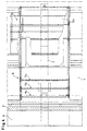
- Switch system 1 are one of two available Stock rails 2 and the tongue 3 assigned to them, which are remote in their distance from the stock rail 2 Position. Both the stock rail 2 and the tongue 3 are in or on a sliding chair 4 or a box sleeper 6 arranged, which is on an upper flange 5 (see. Fig. 3) the box threshold 6 supports. The box threshold 6 takes continue to a slide rod 7, which for locking or unlocking the stock rail 2 with a pivotally mounted Closure clip 8 interacts. This is according to Fig. 1 in an enabling the expansion of the stock rail Location; to remove the stock rail 2 according to the indicated Leaning from its seat in box sleeper 6 or The stock rail tension plate is lifted.
- Each Cover 9, 10 consists of three motion-dependent with each other connected, telescopic, plate-shaped cover elements 11a, 11b, 11c and 12a, 12b, 12c, of which the upper one plate-like cover element 11a or 12a with a vertical web-like stop 13 or 14 bent upwards is formed (see. The stop 14 of the upper cover plate 12a of the inside cover 10 in Fig. 3).
- the tongue end lies in the inner end face 15 the tongue foot 16 to the stop 13 of the upper cover plate 11a of the outside cover 9 and fans or pulls the individual cover elements 11a, 11b, 11c apart, so that the cover 9 the otherwise free area between the the tongue 3 and the stock rail 2 completely sealed off.
- the outer driver leg 17 of the driver 19 lies down namely to the stop 14 of the upper cover plate 12a, so that consequently the movement of the tongue 3 over the driver 19 and transfers the stop 14 to the upper cover element 12a, consequently over the cover elements arranged underneath 12b or 12c pushes.
- the outer driver leg 17 of the Driver 19 is extended downwards; he takes care of you largely flush completion of the stacked Cover elements 12a, 12b, 12c.
- the completely pulled apart and partitioning the area below Cover 9 and the collapsed cover 10 are also 4 seen from the top view.
- the tongue 3 is removed from its in Fig. 1 remote position in the shown in Fig. 2, at the Stock rail 2 adjusts position. Based on these compared to Fig. 1 reversal of movement takes place the inner Driver leg 18 of the driver 19 to the stop 14 of the upper cover member 12a of the inside cover 10 and pulls them to seal off the one below Area apart as shown in Fig. 2. Once the at this movement leading outer driver leg 17 of Driver 19 on the stop 13 of the upper cover 11a hits, this pushes itself over the underlying Cover elements 11b and 11c, one below the top Covering element 11a arranged centering stop 21 (see FIG. 1) for a flush pushing together of the lower cover elements 11b, 11c provides.
- the long sides are inserted in guide grooves 23.
- This can either be cast on the sliding chair 4 or - as in Fig. 3 shown - be formed in guide strips 24, which by means of Screws 25 are attached to the sliding chair 4.
- insulating plate 26 e.g. made of plastic, chambered in combination with the flexible covers 9 and 10 den entire box sleeper range, what a e.g. arranged heating device of the switch setting system of large Meaning is.
Landscapes
- Engineering & Computer Science (AREA)
- Mechanical Engineering (AREA)
- Architecture (AREA)
- Civil Engineering (AREA)
- Structural Engineering (AREA)
- Slide Switches (AREA)
- Lock And Its Accessories (AREA)
- Optical Communication System (AREA)
- Chairs For Special Purposes, Such As Reclining Chairs (AREA)
- Train Traffic Observation, Control, And Security (AREA)
- Switch Cases, Indication, And Locking (AREA)
- Seats For Vehicles (AREA)
- Selective Calling Equipment (AREA)
- Paper (AREA)
Claims (7)
- Système d'aiguillage (1), comprenant des lames mobiles (3) agencées dans des traverses carrées (6) ouvertes vers le haut et des pointes réelles de coeur de croisement mobiles, dans lequel des zones découvertes au-dessus de la traverse carrée (6) sont munies d'un recouvrement flexible, caractérisé en ce qu'un recouvrement flexible (9, 10), composé d'éléments de recouvrement (11a à 11c ou 12a à 12c) en forme de plaque, télescopiques et agencés les uns au-dessus des autres, capable de suivre ou d'éviter automatiquement chaque déplacement de réglage de la lame d'aiguillage ou de la pointe réelle de coeur de croisement.
- Système d'aiguillage selon la revendication 1, caractérisé en ce que les éléments de recouvrement (11a à 11c ou 12a à 12c) s'étendent dans des guides latéraux (23).
- Système d'aiguillage selon la revendication 2, caractérisé en ce que les guides sont réalisés sous forme de rainures longitudinales (23) dans des barres de guidage (24).
- Système d'aiguillage selon la revendication 2, caractérisé par des rainures de guidage (23) coulées intégralement sur la plaque de glissement (4).
- Système d'aiguillage selon l'une quelconque des revendications 1 à 4, caractérisé en ce que les plaques de recouvrement (11a à 11c ou 12a à 12c) sont couplées avec la lame (3) en fonction du déplacement.
- Système d'aiguillage selon l'une quelconque des revendications 1 à 5, caractérisé en ce que l'élément de recouvrement (11a ou 12a) respectivement supérieur des recouvrements (9 ou 10) agencés des deux côtés de la lame mobile (3) est réalisé avec une butée (13 ou 14) faisant saillie vers le haut, auxquels est associé un entraínement (19) présentant deux branches d'entraínement (17, 18) espacées.
- Système d'aiguillage selon l'une quelconque des revendications 1 à 6, caractérisé en ce que le recouvrement (10) côté intérieur est muni d'un élément isolant (26) au niveau de l'extrémité éloignée de la lame (3) vers le bas en direction de la traverse carrée (6).
Applications Claiming Priority (3)
| Application Number | Priority Date | Filing Date | Title |
|---|---|---|---|
| DE19623286A DE19623286A1 (de) | 1996-06-11 | 1996-06-11 | Weichenstellsystem |
| DE19623286 | 1996-06-11 | ||
| PCT/EP1997/003001 WO1997047812A1 (fr) | 1996-06-11 | 1997-06-10 | Systeme de manoeuvre d'aiguille |
Publications (2)
| Publication Number | Publication Date |
|---|---|
| EP0904458A1 EP0904458A1 (fr) | 1999-03-31 |
| EP0904458B1 true EP0904458B1 (fr) | 2001-12-19 |
Family
ID=7796644
Family Applications (1)
| Application Number | Title | Priority Date | Filing Date |
|---|---|---|---|
| EP97925069A Expired - Lifetime EP0904458B1 (fr) | 1996-06-11 | 1997-06-10 | Systeme de manoeuvre d'aiguille |
Country Status (5)
| Country | Link |
|---|---|
| EP (1) | EP0904458B1 (fr) |
| AT (1) | ATE211202T1 (fr) |
| AU (1) | AU3033497A (fr) |
| DE (2) | DE19623286A1 (fr) |
| WO (1) | WO1997047812A1 (fr) |
Families Citing this family (1)
| Publication number | Priority date | Publication date | Assignee | Title |
|---|---|---|---|---|
| AT8698U1 (de) | 2005-08-02 | 2006-11-15 | Vae Gmbh | Abdeckung für antriebs-, verschluss- und/oder prüfergestänge eines weichenantriebs |
Family Cites Families (2)
| Publication number | Priority date | Publication date | Assignee | Title |
|---|---|---|---|---|
| US3312820A (en) * | 1966-02-02 | 1967-04-04 | Watkins Ray | Railroad switch turnout heating apparatus and process of operation thereof |
| DE4315200C2 (de) * | 1993-05-07 | 2003-04-30 | Schwihag Gmbh | Querschwelle mit Verstellvorrichtung für Weichenzungen |
-
1996
- 1996-06-11 DE DE19623286A patent/DE19623286A1/de not_active Withdrawn
-
1997
- 1997-06-10 WO PCT/EP1997/003001 patent/WO1997047812A1/fr not_active Ceased
- 1997-06-10 EP EP97925069A patent/EP0904458B1/fr not_active Expired - Lifetime
- 1997-06-10 DE DE59705897T patent/DE59705897D1/de not_active Expired - Fee Related
- 1997-06-10 AT AT97925069T patent/ATE211202T1/de not_active IP Right Cessation
- 1997-06-10 AU AU30334/97A patent/AU3033497A/en not_active Abandoned
Also Published As
| Publication number | Publication date |
|---|---|
| DE59705897D1 (de) | 2002-01-31 |
| ATE211202T1 (de) | 2002-01-15 |
| WO1997047812A1 (fr) | 1997-12-18 |
| EP0904458A1 (fr) | 1999-03-31 |
| DE19623286A1 (de) | 1997-12-18 |
| AU3033497A (en) | 1998-01-07 |
Similar Documents
| Publication | Publication Date | Title |
|---|---|---|
| DE19846308C2 (de) | Abdicht- und Verriegelungsvorrichtung für Fenster oder Türen | |
| LU88479A1 (de) | Querschwellen f}r Eisenbahn-Gleisanlagen | |
| DE2808809A1 (de) | In einer strassenoberflaeche anbringbarer rahmen und verfahren zu seiner anbringung | |
| EP3296501A1 (fr) | Portail doté d'un élément de porte ainsi qu'élément de fermeture inférieur pour un élément de portail doté d'un élément de porte intégré | |
| DE2258179C3 (de) | Bodenseitige Führung für eine Duschkabinenschiebetür | |
| DE19623286A1 (de) | Weichenstellsystem | |
| WO2009135473A1 (fr) | Porte sectionnelle | |
| DE19814498B4 (de) | Stulpschienenbeschlag | |
| DE10222724B4 (de) | Gliedertor | |
| DE1976119U (de) | Verschlussvorrichtung fuer die fluegel von fenstern, tueren od. dgl. | |
| EP0513554A1 (fr) | Porte coulissante | |
| DE102004042853B3 (de) | Beschlag zur Lagerung mindestens einer Latte | |
| DE2635231A1 (de) | Klammerspitzenverschluss | |
| DE7520486U (de) | Ausstellvorrichtung für aus Metalloder Kunststoffprofilen zusammengesetzte Fenster und Türen o.dgl | |
| DE3239127A1 (de) | Dusch- oder badewannenabtrennung | |
| EP4039925B1 (fr) | Agencement de battant | |
| EP0672811B1 (fr) | Verrouillage de fausse manoeuvre pour une tringle de commande d'une fenêtre, d'une porte ou similaire | |
| DE2932341C2 (de) | Vorhangschleuse | |
| EP2474691B1 (fr) | Porte sectionnelle dotée d'un agencement de verrouillage | |
| DE3805634C2 (fr) | ||
| EP0821131B1 (fr) | Dispositif de sécurité pour fermeture d'une porte enroulable | |
| DE2613738A1 (de) | Einrichtung zur verkeilung oder verriegelung beweglicher teile, insbesondere bei eisenbahnstreckengeraeten | |
| EP0138771A2 (fr) | Dispositif d'étanchéité pour une porte sans seuil | |
| DE1169331B (de) | Beschlag fuer eine aus Lamellengliedern bestehende Schiebetuer | |
| EP2500496B1 (fr) | Agencement de porte |
Legal Events
| Date | Code | Title | Description |
|---|---|---|---|
| PUAI | Public reference made under article 153(3) epc to a published international application that has entered the european phase |
Free format text: ORIGINAL CODE: 0009012 |
|
| 17P | Request for examination filed |
Effective date: 19981209 |
|
| AK | Designated contracting states |
Kind code of ref document: A1 Designated state(s): AT CH DE GB LI |
|
| GRAG | Despatch of communication of intention to grant |
Free format text: ORIGINAL CODE: EPIDOS AGRA |
|
| 17Q | First examination report despatched |
Effective date: 20010214 |
|
| GRAG | Despatch of communication of intention to grant |
Free format text: ORIGINAL CODE: EPIDOS AGRA |
|
| GRAH | Despatch of communication of intention to grant a patent |
Free format text: ORIGINAL CODE: EPIDOS IGRA |
|
| GRAH | Despatch of communication of intention to grant a patent |
Free format text: ORIGINAL CODE: EPIDOS IGRA |
|
| GRAA | (expected) grant |
Free format text: ORIGINAL CODE: 0009210 |
|
| AK | Designated contracting states |
Kind code of ref document: B1 Designated state(s): AT CH DE GB LI |
|
| REF | Corresponds to: |
Ref document number: 211202 Country of ref document: AT Date of ref document: 20020115 Kind code of ref document: T |
|
| REG | Reference to a national code |
Ref country code: CH Ref legal event code: EP |
|
| REG | Reference to a national code |
Ref country code: GB Ref legal event code: IF02 |
|
| REF | Corresponds to: |
Ref document number: 59705897 Country of ref document: DE Date of ref document: 20020131 |
|
| GBT | Gb: translation of ep patent filed (gb section 77(6)(a)/1977) |
Effective date: 20020326 |
|
| REG | Reference to a national code |
Ref country code: CH Ref legal event code: NV Representative=s name: SCHMAUDER & PARTNER AG PATENTANWALTSBUERO |
|
| PLBI | Opposition filed |
Free format text: ORIGINAL CODE: 0009260 |
|
| PLBF | Reply of patent proprietor to notice(s) of opposition |
Free format text: ORIGINAL CODE: EPIDOS OBSO |
|
| 26 | Opposition filed |
Opponent name: SIEMENS AG CT IP TS Effective date: 20020917 |
|
| PLBF | Reply of patent proprietor to notice(s) of opposition |
Free format text: ORIGINAL CODE: EPIDOS OBSO |
|
| PLBF | Reply of patent proprietor to notice(s) of opposition |
Free format text: ORIGINAL CODE: EPIDOS OBSO |
|
| PLBP | Opposition withdrawn |
Free format text: ORIGINAL CODE: 0009264 |
|
| PLBD | Termination of opposition procedure: decision despatched |
Free format text: ORIGINAL CODE: EPIDOSNOPC1 |
|
| PLBM | Termination of opposition procedure: date of legal effect published |
Free format text: ORIGINAL CODE: 0009276 |
|
| STAA | Information on the status of an ep patent application or granted ep patent |
Free format text: STATUS: OPPOSITION PROCEDURE CLOSED |
|
| 27C | Opposition proceedings terminated |
Effective date: 20041216 |
|
| PLAB | Opposition data, opponent's data or that of the opponent's representative modified |
Free format text: ORIGINAL CODE: 0009299OPPO |
|
| PGFP | Annual fee paid to national office [announced via postgrant information from national office to epo] |
Ref country code: CH Payment date: 20080613 Year of fee payment: 12 |
|
| PGFP | Annual fee paid to national office [announced via postgrant information from national office to epo] |
Ref country code: AT Payment date: 20080616 Year of fee payment: 12 |
|
| PGFP | Annual fee paid to national office [announced via postgrant information from national office to epo] |
Ref country code: DE Payment date: 20080620 Year of fee payment: 12 |
|
| PGFP | Annual fee paid to national office [announced via postgrant information from national office to epo] |
Ref country code: GB Payment date: 20080620 Year of fee payment: 12 |
|
| REG | Reference to a national code |
Ref country code: CH Ref legal event code: PCAR Free format text: SCHMAUDER & PARTNER AG PATENT- UND MARKENANWAELTE VSP;ZWAENGIWEG 7;8038 ZUERICH (CH) |
|
| REG | Reference to a national code |
Ref country code: CH Ref legal event code: PL |
|
| GBPC | Gb: european patent ceased through non-payment of renewal fee |
Effective date: 20090610 |
|
| PG25 | Lapsed in a contracting state [announced via postgrant information from national office to epo] |
Ref country code: LI Free format text: LAPSE BECAUSE OF NON-PAYMENT OF DUE FEES Effective date: 20090630 Ref country code: CH Free format text: LAPSE BECAUSE OF NON-PAYMENT OF DUE FEES Effective date: 20090630 |
|
| PG25 | Lapsed in a contracting state [announced via postgrant information from national office to epo] |
Ref country code: GB Free format text: LAPSE BECAUSE OF NON-PAYMENT OF DUE FEES Effective date: 20090610 |
|
| PG25 | Lapsed in a contracting state [announced via postgrant information from national office to epo] |
Ref country code: DE Free format text: LAPSE BECAUSE OF NON-PAYMENT OF DUE FEES Effective date: 20100101 Ref country code: AT Free format text: LAPSE BECAUSE OF NON-PAYMENT OF DUE FEES Effective date: 20090610 |