EP0904469B1 - Als einhebelmischer ausgebildete sanitärarmatur - Google Patents
Als einhebelmischer ausgebildete sanitärarmatur Download PDFInfo
- Publication number
- EP0904469B1 EP0904469B1 EP97926994A EP97926994A EP0904469B1 EP 0904469 B1 EP0904469 B1 EP 0904469B1 EP 97926994 A EP97926994 A EP 97926994A EP 97926994 A EP97926994 A EP 97926994A EP 0904469 B1 EP0904469 B1 EP 0904469B1
- Authority
- EP
- European Patent Office
- Prior art keywords
- valve
- lever
- control
- mixer
- electrically controllable
- Prior art date
- Legal status (The legal status is an assumption and is not a legal conclusion. Google has not performed a legal analysis and makes no representation as to the accuracy of the status listed.)
- Expired - Lifetime
Links
- 239000012530 fluid Substances 0.000 claims abstract description 6
- 230000000694 effects Effects 0.000 claims description 3
- 230000004913 activation Effects 0.000 claims 1
- XLYOFNOQVPJJNP-UHFFFAOYSA-N water Substances O XLYOFNOQVPJJNP-UHFFFAOYSA-N 0.000 description 18
- 230000008901 benefit Effects 0.000 description 3
- 239000007788 liquid Substances 0.000 description 3
- 238000007789 sealing Methods 0.000 description 3
- 230000006835 compression Effects 0.000 description 2
- 238000007906 compression Methods 0.000 description 2
- 230000001276 controlling effect Effects 0.000 description 2
- 230000009471 action Effects 0.000 description 1
- 230000033228 biological regulation Effects 0.000 description 1
- 230000005540 biological transmission Effects 0.000 description 1
- 239000000919 ceramic Substances 0.000 description 1
- 230000007423 decrease Effects 0.000 description 1
- 238000010586 diagram Methods 0.000 description 1
- 238000006073 displacement reaction Methods 0.000 description 1
- 239000000696 magnetic material Substances 0.000 description 1
- 230000007257 malfunction Effects 0.000 description 1
- 239000012528 membrane Substances 0.000 description 1
- 239000000203 mixture Substances 0.000 description 1
- 238000012544 monitoring process Methods 0.000 description 1
- 244000052769 pathogen Species 0.000 description 1
- 230000009467 reduction Effects 0.000 description 1
- 230000001105 regulatory effect Effects 0.000 description 1
- 230000008439 repair process Effects 0.000 description 1
- 125000006850 spacer group Chemical group 0.000 description 1
- 239000008399 tap water Substances 0.000 description 1
- 235000020679 tap water Nutrition 0.000 description 1
- 230000007306 turnover Effects 0.000 description 1
Images

Classifications
-
- E—FIXED CONSTRUCTIONS
- E03—WATER SUPPLY; SEWERAGE
- E03C—DOMESTIC PLUMBING INSTALLATIONS FOR FRESH WATER OR WASTE WATER; SINKS
- E03C1/00—Domestic plumbing installations for fresh water or waste water; Sinks
- E03C1/02—Plumbing installations for fresh water
- E03C1/05—Arrangements of devices on wash-basins, baths, sinks, or the like for remote control of taps
-
- Y—GENERAL TAGGING OF NEW TECHNOLOGICAL DEVELOPMENTS; GENERAL TAGGING OF CROSS-SECTIONAL TECHNOLOGIES SPANNING OVER SEVERAL SECTIONS OF THE IPC; TECHNICAL SUBJECTS COVERED BY FORMER USPC CROSS-REFERENCE ART COLLECTIONS [XRACs] AND DIGESTS
- Y10—TECHNICAL SUBJECTS COVERED BY FORMER USPC
- Y10T—TECHNICAL SUBJECTS COVERED BY FORMER US CLASSIFICATION
- Y10T137/00—Fluid handling
- Y10T137/8593—Systems
- Y10T137/87571—Multiple inlet with single outlet
- Y10T137/87676—With flow control
- Y10T137/87684—Valve in each inlet
- Y10T137/87692—With common valve operator
Definitions
- the invention relates to a single-lever mixer Sanitary fitting according to the features of the preamble of the claim 1.
- Sanitary fittings designed as single-lever mixers are known. They have the mixer taps that used to be common with two manually adjustable valves for cold and warm water largely replaced and usually consist of one Mixer tap with only one operating lever, which has a Control rod a control piston arranged in the mixer tap operated.
- the operating lever is on both sides can also be swiveled vertically. While through the side Swiveling the mixture of cold and warm water is carried out by the vertical pivoting movement regulating the amount of water.
- Single-lever mixer can also be operated without contact.
- a sanitary fitting designed as a single lever mixer after The preamble of claim 1 is known from US-A-5,358,213.
- this known single lever mixer however, one automatic operation to open the valve only in the closed End position of the operating lever possible because in all other manually set positions electrical opening allowing play between the actuators is canceled.
- a sanitary fitting with two is manual adjustable valves for cold and warm water known with a solenoid valve turned on in the outlet channel is. This is done using a proximity switch a control electronics operated as soon as an object enters the monitoring area of the proximity switch. Apart from the not very attractive structure of such a non-contact controlled sanitary fitting at the Parts of the solenoid valve and electrical lines are good are mounted on the spout, this valve has the disadvantage that manual switching on and off, as with conventional manually operated fittings, is no longer possible. So the power supply drops of the solenoid valve for any reason, the armature no more water can be removed.
- the invention is essentially based on the idea that Single-lever mixer tap an electrically controllable Downstream valve, its function not only by the Switching signals of the control electronics depends, but also on the position of the operating lever of the valve.
- the control rod connected to the actuating lever and the electrically controllable valve mechanically coupled that the valve on the one hand despite the corresponding opening signals generated by the proximity sensor etc. remains closed, provided that the mixer tap is closed (the operating lever of the valve is located usually in its lower position).
- the electrically controllable valve remains without a corresponding one Opening signals from the proximity sensor opened, if the mixer tap by operating the control rod is fully open (the valve lever is located usually in its upper position).
- the mechanical control of the valve depending on the Reach the position of the control rod if it is electrically controllable valve around a known solenoid valve acts.
- Such solenoid valves consist of a magnetic switching part and a mechanical valve part.
- the magnetic switching part has one for opening and existing control pin to close the valve on by an electromagnet against the pressure of a spring is axially displaceable.
- a permanent magnet provided the control pin after switching off of the electromagnet in its shifted against the pressure of the spring Holds position.
- Control rod with the permanent magnet of the magnetic switching part mechanically connected via at least one lever. Becomes the axial position of the control rod changed, so it shifts the permanent magnet also changes and changes its distance with respect to the control pin of the switching part, namely such that in the closed position of the mixer tap the permanent magnet no longer has a functionally relevant effect exerts the control pin and in the fully open Position of the control rod of the permanent magnet the control pin constantly attracts.
- the lever is designed as a lever, so that pulling the Control rod movement of the permanent magnet to the control pin towards, the mutual movement of Control rod and permanent magnet through one on the control rod arranged backdrop is set on which the sliding along one end of the bellcrank.
- a major advantage of the single lever mixer according to the invention is that regardless of whether the fitting is operated without contact or in the event of a power failure is operated manually, the mixing function of the valve is not is affected.
- Another major advantage is that the required with conventional single lever mixers Sealing by means of relatively expensive ceramic sealing washers is not necessary can. Because of the sealing function of the mixer tap in its closed position can be low requirements be put because of a perfect seal the downstream solenoid valve is responsible.
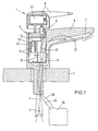
- Fig. 1 denotes a single lever mixer, for example is attached to a sink 2.
- the single lever mixer 1 is both with a cold water pipe 3 as also connected to a hot water pipe 4.
- the single-lever mixer consists of a housing part 5 with a rigid Outlet 6 with outlet channel 7 and a head piece Operating lever 8.
- the operating lever 8 is via an intermediate piece 9 and a control rod 10 with a Mixer tap 11 connected.
- the control rod is 10 via a lever arrangement 12 with the permanent magnet 13 Solenoid valves 14 mechanically connected.
- the water reaches the cold and hot water pipes 3, 4 via corresponding inlets into the mixer tap 11 there according to the position of one with the control rod 10 connected control piston (not shown) mixed and then passes from the outlet 15 of the mixer tap 11 via the Solenoid valve 14 to the outlet channel 7.
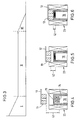
- the solenoid valve 14 (see FIG. 2) is a known pilot valve, which acts as a switching valve is used. It consists of a magnetic switching part 16 and a mechanical valve part 17.
- the switching part 16 contains a control pin 18, the lower one End extends into the valve part 17 and there one Pilot opening 19 of a piston 20 closes.
- the upper The area of the control pin 18 is made from a sleeve 21 surrounded by non-magnetic material, which in turn is within the solenoid 22 of an electromagnet 23 is arranged.
- the upper end face 24 of the control pin 18 is supported by means of a compression spring 25 on the sleeve 21.
- the side facing away from the permanent magnet 13 is the lever arrangement 12 provided with a roller 29 on one the control rod 10 attached rotationally symmetrical backdrop 30 is present.
- the backdrop essentially has three different ones Areas 31-33.
- the liquid inlets and outlets of the solenoid valve 14 are designated by the reference numerals 35 and 36.
- a proximity sensor 37 is provided (FIG. 1), which has a electrical line 38 connected to control electronics 39 is.
- the control electronics 39 is in turn over others electrical lines 40 with both a power source 41, which is accommodated in the form of a battery in the head piece 8 is also connected to the solenoid valve 14.
- FIGS. 3 to 6 of the single-lever mixer 1 according to the invention explained in more detail.
- Figs. 4-6 Pivotal movement of the permanent magnet 13 by displacement of the magnet in the vertical direction.
- the single-lever mixer 1 may be in its closed position Position. This means that the operating lever 8 (Fig. 1) pressed down and the mixer tap 11 is also closed.
- the distance 42 of the permanent magnet is in this position 13 from the end face 24 of the control pin 18 of the Solenoid valves 14 (Fig. 4) chosen so large that the control pin 18 after switching off the electromagnet 23 not from the permanent magnet 13 can be held and by the spring 25 is pushed into its lower switch position.
- the solenoid valve therefore only has a stable one in this case Position in which the control pin, the pilot opening 19 of the Piston 20 closes.
- An electrical opening of the solenoid valve 14, for example due to disturbance variables (e.g. while on vacation), can not.
- the control pen 18 After switching off the electromagnet 23 solely by the Magnetic force of the permanent magnet 13 against the restoring force held by the pen.
- the control pin 18 is in his upper switch position and the valve is open.
- the invention is of course not based on the above described embodiment limited. So, depending on Attachment of the operating lever to the control rod Execution of corresponding functions a reversal of the direction of movement the control rod, so that for actuation of the electrically controlled valve 14 the connecting lever 12 be adapted accordingly to this sequence of movements got to.
- the proximity sensor and electronics not necessarily are a battery arranged in the head piece 8. Rather, a power supply can also be used, which for example, is integrated in the control electronics.
- housing part with mixer tap and Valve and the outlet of the sanitary fitting are not mandatory be combined in one unit.
- bathtub fittings it has proven to be advantageous to both fittings separately on the corresponding one adjacent to the tub Arrange room wall.
Landscapes
- Health & Medical Sciences (AREA)
- Life Sciences & Earth Sciences (AREA)
- Engineering & Computer Science (AREA)
- Hydrology & Water Resources (AREA)
- Public Health (AREA)
- Water Supply & Treatment (AREA)
- Mechanically-Actuated Valves (AREA)
- Domestic Plumbing Installations (AREA)
- Multiple-Way Valves (AREA)
- Food-Manufacturing Devices (AREA)
Applications Claiming Priority (3)
| Application Number | Priority Date | Filing Date | Title |
|---|---|---|---|
| DE19623104A DE19623104C2 (de) | 1996-06-10 | 1996-06-10 | Als Einhebelmischer ausgebildete Sanitärarmatur |
| DE19623104 | 1996-06-10 | ||
| PCT/DE1997/001164 WO1997047828A1 (de) | 1996-06-10 | 1997-06-09 | Als einhebelmischer ausgebildete sanitärarmatur |
Publications (2)
| Publication Number | Publication Date |
|---|---|
| EP0904469A1 EP0904469A1 (de) | 1999-03-31 |
| EP0904469B1 true EP0904469B1 (de) | 2000-05-17 |
Family
ID=7796526
Family Applications (1)
| Application Number | Title | Priority Date | Filing Date |
|---|---|---|---|
| EP97926994A Expired - Lifetime EP0904469B1 (de) | 1996-06-10 | 1997-06-09 | Als einhebelmischer ausgebildete sanitärarmatur |
Country Status (8)
| Country | Link |
|---|---|
| US (1) | US6044865A (ja) |
| EP (1) | EP0904469B1 (ja) |
| JP (1) | JP2000512352A (ja) |
| AT (1) | ATE193074T1 (ja) |
| AU (1) | AU3164997A (ja) |
| DE (2) | DE19623104C2 (ja) |
| ES (1) | ES2150261T3 (ja) |
| WO (1) | WO1997047828A1 (ja) |
Families Citing this family (23)
| Publication number | Priority date | Publication date | Assignee | Title |
|---|---|---|---|---|
| DE29800536U1 (de) * | 1998-01-16 | 1998-03-05 | A. u. K. Müller GmbH & Co KG, 40595 Düsseldorf | Magnetventil, insbesondere für sanitäre Armaturen |
| DE19803817C5 (de) * | 1998-01-31 | 2005-11-03 | Meloh Armaturen Ruppel & Meloh Gmbh | Armatur, insbesondere Wasserarmatur |
| DE29824484U1 (de) | 1998-10-12 | 2001-03-29 | KLUDI-Armaturen Scheffer Vertriebs- und Verwaltungs oHG, 58706 Menden | Kartusche für eine Einhebel-Wassermischarmatur |
| DE19846720A1 (de) * | 1998-10-12 | 2000-04-13 | Kludi Armaturen Scheffer Vertr | Kartusche für eine Einhebel-Wassermischarmatur |
| IT1314777B1 (it) * | 2000-01-25 | 2003-01-16 | Nuova Galatron Srl | Dispositivo di erogazione e miscelazione dell'acqua |
| IT1314778B1 (it) * | 2000-01-25 | 2003-01-16 | Nuova Galatron Srl | Dispositivo per l'erogazione automatica dell'acqua |
| DE10005961A1 (de) * | 2000-02-09 | 2001-08-16 | Grohe Armaturen Friedrich | Wasserauslaufeinrichtung |
| DE10156736A1 (de) | 2001-11-19 | 2003-06-05 | World Of Medicine Lemke Gmbh | Vorrichtung zur manuellen, berührungslosen Betätigung eines elektrischen Gerätes |
| US7537023B2 (en) | 2004-01-12 | 2009-05-26 | Masco Corporation Of Indiana | Valve body assembly with electronic switching |
| DE102005012704B4 (de) * | 2005-03-11 | 2007-06-06 | Hansa Metallwerke Ag | Wassermischarmatur |
| EP1876305A1 (en) * | 2006-07-07 | 2008-01-09 | Hsiang Hung Wang | Mixing faucet with switching from automatic to manual control |
| WO2009103597A2 (de) | 2008-02-20 | 2009-08-27 | Edo Lang | Bedienungsvorrichtung für sanitärobjekte |
| US8302932B2 (en) * | 2009-03-07 | 2012-11-06 | John Sam Bakke | Sprinkler valve test and control device and method thereof |
| DE102009051090B4 (de) | 2009-10-28 | 2012-01-26 | Grohe Ag | Sanitärarmatur |
| US11091901B2 (en) | 2011-07-13 | 2021-08-17 | Delta Faucet Company | Faucet handle with angled interface |
| US8820705B2 (en) | 2011-07-13 | 2014-09-02 | Masco Corporation Of Indiana | Faucet handle with angled interface |
| DE102013011598B4 (de) * | 2013-07-11 | 2017-02-23 | Grohe Ag | Sanitärarmatur mit Mischwelle |
| US20170122456A1 (en) * | 2014-01-09 | 2017-05-04 | Hans-Jörgen Beyer | Valve comprising a variable flow opening |
| CN105546138B (zh) * | 2016-01-22 | 2017-12-26 | 林秀东 | 一种可对流量进行调节并预设的水龙头 |
| DE102016106411B4 (de) | 2016-04-07 | 2024-07-18 | Samson Aktiengesellschaft | Elektropneumatisches Magnetventil |
| CN110296261B (zh) * | 2019-05-16 | 2024-11-22 | 厦门建霖健康家居股份有限公司 | 一种龙头及其操作方法 |
| DE102020104068A1 (de) | 2020-02-17 | 2021-08-19 | Grohe Ag | Sanitäreinrichtung an dessen Betätigungselement eine magnetische Kraft haptisch wahrnehmbar ist |
| CN112377642B (zh) * | 2020-11-11 | 2022-07-05 | 厦门大白科技有限公司 | 一种控制阀组及具有其的龙头和淋浴器 |
Family Cites Families (8)
| Publication number | Priority date | Publication date | Assignee | Title |
|---|---|---|---|---|
| AT233341B (de) * | 1961-09-04 | 1964-05-11 | Kromschroeder Ag G | Ventil |
| DE2533527A1 (de) * | 1975-07-26 | 1977-01-27 | Dalferth Gotthilf R | Vorrichtung zur abgabe von fluessigkeiten ueber einen auslauf |
| GB2141597B (en) * | 1983-06-14 | 1987-02-11 | Dobson Park Ind | Electrically operated valve |
| DE3670327D1 (de) * | 1986-05-12 | 1990-05-17 | Dmp Electronics Srl | Armatur fuer die abgabe von fluessigkeiten mit umschaltung von automatischer auf manuelle steuerung. |
| GB2206397A (en) * | 1987-07-01 | 1989-01-05 | Chong Lih Electric Industry Co | Photoelectrically-controlled faucet structure |
| US5358213A (en) * | 1993-03-31 | 1994-10-25 | Pilolla Joseph J | Faucet having automatic and manual control capability |
| DE4420331A1 (de) * | 1994-06-10 | 1995-12-14 | Grohe Armaturen Friedrich | Wasserarmatur mit Mischventil |
| US5529281A (en) * | 1994-08-24 | 1996-06-25 | The United States Of America As Represented By The Administrator Of National Aeronautics And Space | Dual-latching solenoid-actuated valve assembly |
-
1996
- 1996-06-10 DE DE19623104A patent/DE19623104C2/de not_active Expired - Fee Related
-
1997
- 1997-06-09 ES ES97926994T patent/ES2150261T3/es not_active Expired - Lifetime
- 1997-06-09 JP JP50106198A patent/JP2000512352A/ja active Pending
- 1997-06-09 DE DE59701723T patent/DE59701723D1/de not_active Expired - Fee Related
- 1997-06-09 AT AT97926994T patent/ATE193074T1/de not_active IP Right Cessation
- 1997-06-09 US US09/202,162 patent/US6044865A/en not_active Expired - Fee Related
- 1997-06-09 WO PCT/DE1997/001164 patent/WO1997047828A1/de not_active Ceased
- 1997-06-09 EP EP97926994A patent/EP0904469B1/de not_active Expired - Lifetime
- 1997-06-09 AU AU31649/97A patent/AU3164997A/en not_active Abandoned
Also Published As
| Publication number | Publication date |
|---|---|
| ES2150261T3 (es) | 2000-11-16 |
| US6044865A (en) | 2000-04-04 |
| DE19623104C2 (de) | 2001-09-27 |
| EP0904469A1 (de) | 1999-03-31 |
| DE19623104A1 (de) | 1997-12-11 |
| JP2000512352A (ja) | 2000-09-19 |
| DE59701723D1 (de) | 2000-06-21 |
| ATE193074T1 (de) | 2000-06-15 |
| WO1997047828A1 (de) | 1997-12-18 |
| AU3164997A (en) | 1998-01-07 |
Similar Documents
| Publication | Publication Date | Title |
|---|---|---|
| DE19623104C2 (de) | Als Einhebelmischer ausgebildete Sanitärarmatur | |
| DE60006928T2 (de) | Vorrichtung zum Abgeben und Mischen von Wasser | |
| DE19508631C1 (de) | Durchflußbegrenzendes Ventil zum Einfügen zwischen einen Brauseschlauch und eine Handbrause | |
| EP2099341A1 (de) | Getränkebereitungsmaschine mit quetschventil | |
| EP1130177A2 (de) | Wasserauslaufventilanordnung | |
| EP0432440B1 (de) | Elektrisch gesteuerte Armatur | |
| DE60008853T2 (de) | Vorrichtung zur automatischen Wasserabgabe | |
| CH658485A5 (de) | Sanitaerinstallation mit wenigstens einer steuerarmatur und separater wasserausgabevorrichtung. | |
| EP2406432A1 (de) | Wasserarmatur mit kartusche unter der sanitärkeramik | |
| DE102007048026A1 (de) | Energiesparender Einhebelmischer als Mischbatterie und sanitäre Auslaufarmatur bzw. Mischarmatur | |
| EP1794377B1 (de) | Sanitäre unterputzarmatur | |
| DE1550154A1 (de) | Umschaltbarer Wasserhahn | |
| CH621378A5 (en) | Upwardly directed shower device for WCs | |
| EP2085669B1 (de) | Sanitärarmatur | |
| DE10320636B3 (de) | Wasserhahn | |
| DE3841911C2 (de) | Sanitärarmatur | |
| DE69900135T2 (de) | Impulsgesteuertes, elektromagnetisches Hydraulikventil | |
| DE3626215C2 (ja) | ||
| DE102005011984B4 (de) | Elektrisch betriebene Standardarmatur mit getrennt angeordneten Funktionseinheiten | |
| DE4141172B4 (de) | Vorrichtung zum Umstellen eines Ventilgliedes an einer Sanitärarmatur | |
| DE69406198T2 (de) | Mischventil mit elektromagnetischem Membranventil | |
| DE10027561C1 (de) | Ventil | |
| DE3626624C2 (ja) | ||
| CH587041A5 (en) | Public shower bath with electromagnetic valve - has time delay switch in supply line to prevent waste of water | |
| EP3502365B1 (de) | Sanitärer gegenstand, insbesondere spülkasten oder ablauf- oder füllventil für einen spülkasten |
Legal Events
| Date | Code | Title | Description |
|---|---|---|---|
| PUAI | Public reference made under article 153(3) epc to a published international application that has entered the european phase |
Free format text: ORIGINAL CODE: 0009012 |
|
| 17P | Request for examination filed |
Effective date: 19981202 |
|
| AK | Designated contracting states |
Kind code of ref document: A1 Designated state(s): AT BE CH DE DK ES FI FR GB GR IE IT LI LU MC NL PT SE |
|
| GRAG | Despatch of communication of intention to grant |
Free format text: ORIGINAL CODE: EPIDOS AGRA |
|
| 17Q | First examination report despatched |
Effective date: 19990504 |
|
| GRAG | Despatch of communication of intention to grant |
Free format text: ORIGINAL CODE: EPIDOS AGRA |
|
| GRAH | Despatch of communication of intention to grant a patent |
Free format text: ORIGINAL CODE: EPIDOS IGRA |
|
| GRAH | Despatch of communication of intention to grant a patent |
Free format text: ORIGINAL CODE: EPIDOS IGRA |
|
| GRAA | (expected) grant |
Free format text: ORIGINAL CODE: 0009210 |
|
| AK | Designated contracting states |
Kind code of ref document: B1 Designated state(s): AT BE CH DE DK ES FI FR GB GR IE IT LI LU MC NL PT SE |
|
| PG25 | Lapsed in a contracting state [announced via postgrant information from national office to epo] |
Ref country code: NL Free format text: LAPSE BECAUSE OF FAILURE TO SUBMIT A TRANSLATION OF THE DESCRIPTION OR TO PAY THE FEE WITHIN THE PRESCRIBED TIME-LIMIT Effective date: 20000517 Ref country code: GR Free format text: LAPSE BECAUSE OF NON-PAYMENT OF DUE FEES Effective date: 20000517 Ref country code: FI Free format text: LAPSE BECAUSE OF FAILURE TO SUBMIT A TRANSLATION OF THE DESCRIPTION OR TO PAY THE FEE WITHIN THE PRESCRIBED TIME-LIMIT Effective date: 20000517 |
|
| REF | Corresponds to: |
Ref document number: 193074 Country of ref document: AT Date of ref document: 20000615 Kind code of ref document: T |
|
| REG | Reference to a national code |
Ref country code: IE Ref legal event code: FG4D Free format text: GERMAN Ref country code: CH Ref legal event code: EP |
|
| PG25 | Lapsed in a contracting state [announced via postgrant information from national office to epo] |
Ref country code: LU Free format text: LAPSE BECAUSE OF NON-PAYMENT OF DUE FEES Effective date: 20000609 |
|
| REF | Corresponds to: |
Ref document number: 59701723 Country of ref document: DE Date of ref document: 20000621 |
|
| PG25 | Lapsed in a contracting state [announced via postgrant information from national office to epo] |
Ref country code: BE Free format text: LAPSE BECAUSE OF NON-PAYMENT OF DUE FEES Effective date: 20000630 |
|
| PG25 | Lapsed in a contracting state [announced via postgrant information from national office to epo] |
Ref country code: MC Free format text: THE PATENT HAS BEEN ANNULLED BY A DECISION OF A NATIONAL AUTHORITY Effective date: 20000717 |
|
| ITF | It: translation for a ep patent filed | ||
| PG25 | Lapsed in a contracting state [announced via postgrant information from national office to epo] |
Ref country code: SE Free format text: LAPSE BECAUSE OF FAILURE TO SUBMIT A TRANSLATION OF THE DESCRIPTION OR TO PAY THE FEE WITHIN THE PRESCRIBED TIME-LIMIT Effective date: 20000817 Ref country code: PT Free format text: LAPSE BECAUSE OF FAILURE TO SUBMIT A TRANSLATION OF THE DESCRIPTION OR TO PAY THE FEE WITHIN THE PRESCRIBED TIME-LIMIT Effective date: 20000817 Ref country code: DK Free format text: LAPSE BECAUSE OF FAILURE TO SUBMIT A TRANSLATION OF THE DESCRIPTION OR TO PAY THE FEE WITHIN THE PRESCRIBED TIME-LIMIT Effective date: 20000817 |
|
| GBT | Gb: translation of ep patent filed (gb section 77(6)(a)/1977) |
Effective date: 20000811 |
|
| ET | Fr: translation filed | ||
| REG | Reference to a national code |
Ref country code: CH Ref legal event code: NV Representative=s name: ISLER & PEDRAZZINI AG |
|
| NLV1 | Nl: lapsed or annulled due to failure to fulfill the requirements of art. 29p and 29m of the patents act | ||
| REG | Reference to a national code |
Ref country code: ES Ref legal event code: FG2A Ref document number: 2150261 Country of ref document: ES Kind code of ref document: T3 |
|
| BERE | Be: lapsed |
Owner name: SANITECH G.M.B.H. Effective date: 20000630 |
|
| REG | Reference to a national code |
Ref country code: IE Ref legal event code: FD4D |
|
| PLBE | No opposition filed within time limit |
Free format text: ORIGINAL CODE: 0009261 |
|
| STAA | Information on the status of an ep patent application or granted ep patent |
Free format text: STATUS: NO OPPOSITION FILED WITHIN TIME LIMIT |
|
| 26N | No opposition filed | ||
| PGFP | Annual fee paid to national office [announced via postgrant information from national office to epo] |
Ref country code: GB Payment date: 20010612 Year of fee payment: 5 |
|
| PGFP | Annual fee paid to national office [announced via postgrant information from national office to epo] |
Ref country code: FR Payment date: 20010627 Year of fee payment: 5 |
|
| PGFP | Annual fee paid to national office [announced via postgrant information from national office to epo] |
Ref country code: AT Payment date: 20010628 Year of fee payment: 5 |
|
| PGFP | Annual fee paid to national office [announced via postgrant information from national office to epo] |
Ref country code: CH Payment date: 20010705 Year of fee payment: 5 |
|
| REG | Reference to a national code |
Ref country code: GB Ref legal event code: IF02 |
|
| PG25 | Lapsed in a contracting state [announced via postgrant information from national office to epo] |
Ref country code: GB Free format text: LAPSE BECAUSE OF NON-PAYMENT OF DUE FEES Effective date: 20020609 Ref country code: AT Free format text: LAPSE BECAUSE OF NON-PAYMENT OF DUE FEES Effective date: 20020609 |
|
| PG25 | Lapsed in a contracting state [announced via postgrant information from national office to epo] |
Ref country code: LI Free format text: LAPSE BECAUSE OF NON-PAYMENT OF DUE FEES Effective date: 20020630 Ref country code: CH Free format text: LAPSE BECAUSE OF NON-PAYMENT OF DUE FEES Effective date: 20020630 |
|
| GBPC | Gb: european patent ceased through non-payment of renewal fee |
Effective date: 20020609 |
|
| REG | Reference to a national code |
Ref country code: CH Ref legal event code: PL |
|
| PG25 | Lapsed in a contracting state [announced via postgrant information from national office to epo] |
Ref country code: FR Free format text: LAPSE BECAUSE OF NON-PAYMENT OF DUE FEES Effective date: 20030228 |
|
| REG | Reference to a national code |
Ref country code: FR Ref legal event code: ST |
|
| PGFP | Annual fee paid to national office [announced via postgrant information from national office to epo] |
Ref country code: ES Payment date: 20031113 Year of fee payment: 7 |
|
| PG25 | Lapsed in a contracting state [announced via postgrant information from national office to epo] |
Ref country code: ES Free format text: LAPSE BECAUSE OF NON-PAYMENT OF DUE FEES Effective date: 20040610 |
|
| PG25 | Lapsed in a contracting state [announced via postgrant information from national office to epo] |
Ref country code: IT Free format text: LAPSE BECAUSE OF NON-PAYMENT OF DUE FEES;WARNING: LAPSES OF ITALIAN PATENTS WITH EFFECTIVE DATE BEFORE 2007 MAY HAVE OCCURRED AT ANY TIME BEFORE 2007. THE CORRECT EFFECTIVE DATE MAY BE DIFFERENT FROM THE ONE RECORDED. Effective date: 20050609 |
|
| REG | Reference to a national code |
Ref country code: ES Ref legal event code: FD2A Effective date: 20040610 |
|
| PGFP | Annual fee paid to national office [announced via postgrant information from national office to epo] |
Ref country code: DE Payment date: 20070425 Year of fee payment: 11 |
|
| PG25 | Lapsed in a contracting state [announced via postgrant information from national office to epo] |
Ref country code: DE Free format text: LAPSE BECAUSE OF NON-PAYMENT OF DUE FEES Effective date: 20090101 |