EP0904526B1 - Procede et appareil permettant de surveiller la performance de fonctionnement de systemes de stockage de fluides - Google Patents
Procede et appareil permettant de surveiller la performance de fonctionnement de systemes de stockage de fluides Download PDFInfo
- Publication number
- EP0904526B1 EP0904526B1 EP97927925A EP97927925A EP0904526B1 EP 0904526 B1 EP0904526 B1 EP 0904526B1 EP 97927925 A EP97927925 A EP 97927925A EP 97927925 A EP97927925 A EP 97927925A EP 0904526 B1 EP0904526 B1 EP 0904526B1
- Authority
- EP
- European Patent Office
- Prior art keywords
- volume
- tank
- data
- measurement
- product
- Prior art date
- Legal status (The legal status is an assumption and is not a legal conclusion. Google has not performed a legal analysis and makes no representation as to the accuracy of the status listed.)
- Expired - Lifetime
Links
- 238000000034 method Methods 0.000 title claims description 62
- 238000003860 storage Methods 0.000 title claims description 46
- 239000012530 fluid Substances 0.000 title claims description 31
- 238000012544 monitoring process Methods 0.000 title claims description 24
- 238000005259 measurement Methods 0.000 claims description 101
- 239000011159 matrix material Substances 0.000 claims description 58
- 238000007619 statistical method Methods 0.000 claims description 11
- 238000009529 body temperature measurement Methods 0.000 claims description 10
- 238000005192 partition Methods 0.000 claims description 10
- 238000012545 processing Methods 0.000 claims description 10
- 239000000523 sample Substances 0.000 claims description 8
- 238000000611 regression analysis Methods 0.000 claims description 6
- 230000008859 change Effects 0.000 claims description 5
- 238000012937 correction Methods 0.000 claims description 3
- 230000000737 periodic effect Effects 0.000 claims description 3
- 230000007547 defect Effects 0.000 claims description 2
- 238000012384 transportation and delivery Methods 0.000 description 69
- 230000001186 cumulative effect Effects 0.000 description 45
- 238000004458 analytical method Methods 0.000 description 22
- 238000006243 chemical reaction Methods 0.000 description 20
- 230000006870 function Effects 0.000 description 20
- 238000004364 calculation method Methods 0.000 description 18
- 238000004422 calculation algorithm Methods 0.000 description 14
- 238000007792 addition Methods 0.000 description 12
- 230000000694 effects Effects 0.000 description 12
- 238000004891 communication Methods 0.000 description 9
- 238000007726 management method Methods 0.000 description 9
- GBPZYMBDOBODNK-LBAQZLPGSA-N ethyl (2s)-2-[[2-acetamido-3-[4-[bis(2-chloroethyl)amino]phenyl]propanoyl]amino]-4-methylpentanoate Chemical compound CCOC(=O)[C@H](CC(C)C)NC(=O)C(NC(C)=O)CC1=CC=C(N(CCCl)CCCl)C=C1 GBPZYMBDOBODNK-LBAQZLPGSA-N 0.000 description 8
- 239000000446 fuel Substances 0.000 description 8
- 238000001514 detection method Methods 0.000 description 7
- 238000010586 diagram Methods 0.000 description 7
- 230000007613 environmental effect Effects 0.000 description 7
- 230000009897 systematic effect Effects 0.000 description 7
- 238000013144 data compression Methods 0.000 description 5
- 238000005457 optimization Methods 0.000 description 5
- 238000009826 distribution Methods 0.000 description 4
- 230000007257 malfunction Effects 0.000 description 4
- 239000000463 material Substances 0.000 description 4
- 238000012360 testing method Methods 0.000 description 4
- 230000005540 biological transmission Effects 0.000 description 3
- 230000005484 gravity Effects 0.000 description 3
- 230000010354 integration Effects 0.000 description 3
- 239000007788 liquid Substances 0.000 description 3
- 239000003208 petroleum Substances 0.000 description 3
- 238000013519 translation Methods 0.000 description 3
- 230000014616 translation Effects 0.000 description 3
- XLYOFNOQVPJJNP-UHFFFAOYSA-N water Substances O XLYOFNOQVPJJNP-UHFFFAOYSA-N 0.000 description 3
- 230000009471 action Effects 0.000 description 2
- 230000006378 damage Effects 0.000 description 2
- 238000013480 data collection Methods 0.000 description 2
- 238000005516 engineering process Methods 0.000 description 2
- 238000009434 installation Methods 0.000 description 2
- 230000007774 longterm Effects 0.000 description 2
- 238000002156 mixing Methods 0.000 description 2
- 239000000203 mixture Substances 0.000 description 2
- 230000008569 process Effects 0.000 description 2
- 230000001105 regulatory effect Effects 0.000 description 2
- 230000001932 seasonal effect Effects 0.000 description 2
- 238000012546 transfer Methods 0.000 description 2
- 230000007704 transition Effects 0.000 description 2
- 238000012795 verification Methods 0.000 description 2
- NCGICGYLBXGBGN-UHFFFAOYSA-N 3-morpholin-4-yl-1-oxa-3-azonia-2-azanidacyclopent-3-en-5-imine;hydrochloride Chemical compound Cl.[N-]1OC(=N)C=[N+]1N1CCOCC1 NCGICGYLBXGBGN-UHFFFAOYSA-N 0.000 description 1
- 238000012935 Averaging Methods 0.000 description 1
- 241000220010 Rhode Species 0.000 description 1
- 238000009825 accumulation Methods 0.000 description 1
- 239000000654 additive Substances 0.000 description 1
- 230000000996 additive effect Effects 0.000 description 1
- 230000033228 biological regulation Effects 0.000 description 1
- 230000015556 catabolic process Effects 0.000 description 1
- 238000007906 compression Methods 0.000 description 1
- 230000006835 compression Effects 0.000 description 1
- 238000013500 data storage Methods 0.000 description 1
- 230000007812 deficiency Effects 0.000 description 1
- 238000006731 degradation reaction Methods 0.000 description 1
- 238000012217 deletion Methods 0.000 description 1
- 230000037430 deletion Effects 0.000 description 1
- 238000013461 design Methods 0.000 description 1
- 238000003745 diagnosis Methods 0.000 description 1
- 238000002405 diagnostic procedure Methods 0.000 description 1
- -1 diesel Substances 0.000 description 1
- 238000003891 environmental analysis Methods 0.000 description 1
- 238000011156 evaluation Methods 0.000 description 1
- 239000011152 fibreglass Substances 0.000 description 1
- 238000009472 formulation Methods 0.000 description 1
- 239000003502 gasoline Substances 0.000 description 1
- 238000009499 grossing Methods 0.000 description 1
- 230000000977 initiatory effect Effects 0.000 description 1
- 238000011835 investigation Methods 0.000 description 1
- 239000003350 kerosene Substances 0.000 description 1
- 238000004519 manufacturing process Methods 0.000 description 1
- TVMXDCGIABBOFY-UHFFFAOYSA-N octane Chemical compound CCCCCCCC TVMXDCGIABBOFY-UHFFFAOYSA-N 0.000 description 1
- 230000001151 other effect Effects 0.000 description 1
- 239000002245 particle Substances 0.000 description 1
- 239000003209 petroleum derivative Substances 0.000 description 1
- 238000000053 physical method Methods 0.000 description 1
- 238000013439 planning Methods 0.000 description 1
- 238000007639 printing Methods 0.000 description 1
- 238000005086 pumping Methods 0.000 description 1
- 230000009467 reduction Effects 0.000 description 1
- 238000005067 remediation Methods 0.000 description 1
- 230000003252 repetitive effect Effects 0.000 description 1
- 230000004044 response Effects 0.000 description 1
- 239000010802 sludge Substances 0.000 description 1
- 239000007787 solid Substances 0.000 description 1
- 230000003068 static effect Effects 0.000 description 1
- 230000002277 temperature effect Effects 0.000 description 1
- 238000012731 temporal analysis Methods 0.000 description 1
- 230000002123 temporal effect Effects 0.000 description 1
- 238000000700 time series analysis Methods 0.000 description 1
- 230000000007 visual effect Effects 0.000 description 1
- 230000003442 weekly effect Effects 0.000 description 1
Images


Classifications
-
- G—PHYSICS
- G01—MEASURING; TESTING
- G01F—MEASURING VOLUME, VOLUME FLOW, MASS FLOW OR LIQUID LEVEL; METERING BY VOLUME
- G01F23/00—Indicating or measuring liquid level or level of fluent solid material, e.g. indicating in terms of volume or indicating by means of an alarm
- G01F23/80—Arrangements for signal processing
- G01F23/802—Particular electronic circuits for digital processing equipment
- G01F23/804—Particular electronic circuits for digital processing equipment containing circuits handling parameters other than liquid level
Definitions
- the invention relates to monitoring the operational performance of fluid storage systems.
- underground storage tanks and, occasionally, above-ground storage tanks (AST's) are used to store petroleum products and fuel to be dispensed at automobile service stations, trucking terminals, automobile rental outlets, and similar operations through gasoline, diesel, or kerosene dispensing pumps.
- Fuel product is generally delivered to such facilities by a gravity drop from a compartment in a wheeled transport means such as a fuel delivery truck.
- AST's or UST's are often located at central distribution locations so that product can be subsequently withdrawn from the tank system to be transported for delivery to a variety of such facilities.
- a distribution location with UST's or AST's may receive deliveries of product from, e.g., a pipeline spur, wheeled transport, a barge, or a rail car.
- SIR Statistical Inventory Reconciliation
- the present invention relates to an automatic SIR system that may continuously and automatically collect data from completely above-ground, partially above-ground, and completely below ground containers for statistical analysis.
- the invention addresses a variety of physical, business, operational and environmental issues associated with the bulk storage of liquids or pourable solids.
- the present invention is an application of SIR that greatly enhances the ability to manage a facility effectively. It provides the means to characterize exactly the geometry, dimensions, and configuration of the storage vessel, identify overages and shortages in deliveries and unexplained additions and removals of product, and provide an accurate assessment of overall dispensing meter calibration. In addition, by accounting for such discrepancies, the present invention permits identification of leakage at rates less than .1 gallon per hour in all of its estimates to any prescribed tolerance. By increasing the number of measurements taken, the estimates can be derived at any desired level of tolerance.
- the method of the present invention makes no assumptions as to the precision of any of the measuring devices used in various system configurations. Precision and calibration accuracies are derived from the data alone. Also, it is not assumed that the tank system is leak free; the leak status of the system is determined from the data alone.
- the method derives tank geometry, dimensions, and configuration, and their impact on the totality of cumulative inventory variances, as a function of product height in the tank. Correctness of dispensing meter calibration is verified in a similar manner by testing for randomness of cumulative variances as a function of varying sales volumes. Having confirmed that such remaining residual variances are random, reflecting only the inherent random noise of the measurement devices, the present method analyzes departures of the cumulative variance from the bounds determined by the calculated random noise level. All calculations as to the volumes added, removed, metered or leaking are based upon extended successive, simultaneous observations of meter and gauge readings. The number of observations incorporated in each such calculation is determined by computing confidence bands for the parameters of interest and extending data collection as necessary to achieve predetermined tolerances.
- the method of the present invention is capable of distinguishing between continuous losses consistent with leakage and one-time unexplained removals of the fluid product from the tank.
- the method may be used to ensure the accuracy of computed delivery volumes, which are determined and reported with confidence boundaries calculated for estimated delivered quantities.
- the method can also be used to control and monitor the accuracy of purchase costs of fluids such as petroleum which are delivered to tanks.
- fluids such as petroleum which are delivered to tanks.
- motor fuel retailers may be charged by wholesalers for either net or gross volumes purported to have been delivered.
- a determination that purchase charges are appropriate thus requires frequent simultaneous readings of sales, tank volumes and temperatures, which can be accomplished using the method of the present invention.
- the present invention involves estimating changes in product volume in a tank based on multiple data points and their respective likely errors measured continuously over a period of time.
- a software program is used to implement an algorithm that employs concepts from matrix theory and mathematical statistics.
- the algorithm includes generating the product of a matrix and its transpose by successive additions of partial products of partitions of the matrix and their corresponding transposed matrix partitions to minimize the storage requirements of the data collected.
- the compressed matrix data constitutes a complete and sufficient statistic for the parameters of interest.
- the algorithm thus permits the accumulation and storage of a large amount of data in a condensed form without sacrificing statistically useful information, to obtain a statistically significant result with the required accuracy and reliability.
- one object of the present invention is to determine the accuracy and consistency of devices used to measure volume of product added to, removed from, and present in a fluid storage system.
- Another object of the invention is to identify and quantify additions of material to the system, but not recorded as such, and volumes of product removed from the system which are not registered by measuring devices or otherwise recorded.
- Another object of the invention is to discriminate between discrete one-time unrecorded removals of product from the system and continuous losses consistent with leakage.
- Another object of the invention is to identify and provide early warning of product leakage from all parts of the system, extending from the fill point to the point of discharge, and to confirm the validity of resulting leakage warnings.
- Another object of the invention is to determine secular, seasonal trends and repetitive special demands to provide short and long term estimates for demand of the product, and to provide optimal reorder quantities and a delivery schedule for the system.
- a further object of this invention is to accomplish all of the foregoing in a fully automated system that requires no human intervention, other than as an option available to the operator to enter quantities of material reportedly delivered for comparison with those computed.
- the invention features a method of monitoring a fluid storage and dispensing system.
- the system has measurement apparatus for measuring a volume associated with the system.
- a plurality of measurement data is collected from the measurement apparatus in a form readable by a computer and stored in a compressed matrix format in a computer memory.
- the compressed matrix format is statistically analyzed to determine operational monitoring information.
- the statistically analyzing step includes calculating error data resulting from the measurement apparatus.
- the method may also include determining the presence of operational defects in the system, monitoring the accuracy of the measurement apparatus, determining the volume of fluid in the system, and determining whether a quantity of fluid removed from the system is caused by a leak in the system.
- the method also may include delivering a warning that a leak has been detected in the system.
- the collecting step may be performed while the system is operating, may be performed continuously at periodic intervals, and may be performed automatically under the control of the computer.
- the method may include querying the measurement apparatus under the control of the computer.
- the method may include measuring the temperature of the fluid and calculating the volume based on the temperature of the volume in the system.
- the calculating step may include determining a correction value based on a weighted average of the temperature of the volume measured at a plurality of locations within the system.
- the system may include a plurality of tanks, including an underground storage tank, an above-ground storage tank, or a partially above-ground storage tank.
- the storing step may include generating the compressed matrix format as a product of a data matrix and the transpose of the data matrix. Further, the product may be formed by addition of partial products of each of a plurality of partitions of the data matrix with the transpose of each of the partitions.
- the measurement apparatus may include a volumetric gauge, a dispensing apparatus and a sales recording device.
- the measurement data or the compressed matrix format may be transmitted to a host processor to perform the statistical analysis.
- the collecting step also may include estimating an initial volume of fluid in the system.
- the invention features a method of monitoring a fluid storage and dispensing system.
- the system includes measurement apparatus for measuring a volume associated with the system.
- a plurality of measurement data is collected from the measurement apparatus in a form readable by a computer and stored in a compressed matrix format in a computer memory.
- the compressed matrix format is statistically analyzed, to determine whether a quantity of fluid removed from the system is caused by a leak in the system.
- a warning that a leak has been detected in the system is delivered.
- the invention features an apparatus for monitoring a fluid storage and dispensing system.
- Measurement apparatus measure a volume associated with the system.
- a computer includes a processing means for collecting a plurality of measurement data from the measurement apparatus and a memory for storing the plurality of measurement data in a compressed matrix format.
- the processing means performs statistical analysis of the compressed matrix format to determine operational monitoring information.
- the system may include a plurality of tanks, including an underground storage tank, an above-ground storage tank, or a partially above-ground storage tank.
- the measurement apparatus may include a volumetric gauge, a dispensing apparatus and a sales recording device.
- the volumetric gauge may include a probe disposed in the system, and the probe may be a magnetostrictive tank probe.
- the dispensing apparatus may include a totalizer.
- the sales recording device may simulate operation of a point of sale terminal. Also, the measurement data may be collected simultaneously from the various measurement apparatus.
- the system may include a temperature sensor disposed in the system in contact with the volume for obtaining a temperature measurement in the volume.
- the system may include a plurality of temperature sensors disposed at different locations within the system, each of the sensors being in contact with the volume for obtaining a plurality of temperature measurements of the volume. The temperature measurements may be used to calculate the volume.
- the measurement data obtained from the measurement apparatus may be transmitted to the computer.
- a host processor remote from the computer may perform the statistical analysis.
- the compressed matrix format may be generated as a product of a data matrix and the transpose of the data matrix. Further, the product may be formed by addition of partial products of each of a plurality of partitions of the data matrix with the transpose of each of the partitions.
- the invention features a method of monitoring a fluid storage and dispensing system.
- the system has a plurality of measurement apparatus for measuring a volume associated with the system.
- Measurement data is simultaneously collected from the plurality of measurement apparatus in a form readable by a computer to determine a change in the volume.
- the collecting step is repeated to obtain a plurality of measurement data from the plurality of measurement apparatus.
- the plurality of measurement data is stored in a compressed matrix format in a computer memory, and the compressed matrix format is statistically analyzed to determine operational monitoring information.
- Implementation of the invention may also include the following feature.
- the method may include estimating an initial value of the volume during the analyzing step.
- the invention features a method of monitoring a fluid storage and dispensing system.
- the system has measurement apparatus for measuring a volume associated with the system and a plurality of temperature sensing devices located at different heights in the system.
- the volume has a height in the system.
- a plurality of volume measurement data is collected from the measurement apparatus in a form readable by a computer.
- the volume measurement data is adjusted based on temperature measurements taken from those of the plurality of temperature sensing devices at a height below the height of the volume in the system.
- the plurality of volume measurement data is stored in a compressed matrix format in a computer memory, and the compressed matrix format is statistically analyzed to determine operational monitoring information.
- the invention features a method of determining a volume associated with a fluid storage and dispensing system.
- the volume has a height in the system, and the system has measurement apparatus for measuring the height.
- a plurality of height measurement data is collected from the measurement apparatus in a form readable by a computer.
- the plurality of height measurement data is stored in a compressed matrix format in a computer memory. Regression analysis is performed using the compressed matrix format to calculate the volume associated with the system.
- the collecting step may be performed each time a portion of the volume is dispensed from the system.
- the collecting step may not be performed when the fluid is being added to the system.
- the invention features an apparatus for determining a volume associated with a fluid storage and dispensing system.
- the volume has a height in the system, and measurement apparatus measures the height of the volume.
- a computer has a processing means for collecting a plurality of height measurement data from the measurement apparatus and a memory for storing the plurality of height measurement data in a compressed matrix format.
- the processing means performs regression analysis of the compressed matrix format to determine the volume associated with the system.
- the invention features a method of determining a plurality of volumes, each of the volumes associated with one of a plurality of fluid storage and dispensing systems.
- Each of the volumes has a height in its associated system, and each of the systems has measurement apparatus for measuring the height for each of the volumes.
- a plurality of height measurement data is collected from the measurement apparatus of each of the plurality of systems in a form readable by a computer.
- the plurality of height measurement data is stored in a compressed matrix format in a computer memory. Regression analysis is performed using the compressed matrix format to calculate the volumes associated with the systems.
- the method and apparatus described herein applies to UST's, AST's or any type of storage tank.
- the product stored in the tank may be any fluid, including dry particles that flow in the manner of a fluid.
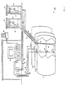
- FIG. 1 shows a UST facility 10, illustrated as an automobile service station.
- Facility 10 includes a series of UST's 12, 14, 16 which may store the same or different types of liquid fuel product 18.
- Volumetric tank gauges 20, 22, 24 in each tank measure the height of product 18 in the tank.
- Submersible pumps 26, 28, 30 in each tank pump product 18 to one of dispensing pumps 32, 34 through piping lines 36, 38, 40.
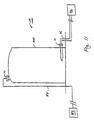
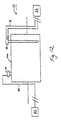
- facility 10 may be an AST facility with above-ground tank 1000, as shown in Fig. 11, or a facility with a partially above-ground tank 1010, as shown in Fig. 12.
- Tank gauges 20, 22, 24 are mounted in tanks 12, 14, 16.
- the tank gauges may consist of or be based on magnetostrictive tank probes or other sensing technologies.
- magnetostrictive technology two floats 42, 44 surround each probe, e.g., gauge 20 in tank 12.
- One float 42 floats on the upper surface of product 18 in tank 12, and the other float 44 floats on the interface of product 18 with any water or other foreign material collected at the bottom of tank 12.
- Tank gauge 20 determines the distance between floats 42, 44 to obtain the height of product 18 in tank 12.
- Tank gauge 20 also contains temperature sensors 46, 48, 50 spaced along its length to monitor the temperature of product 18 at various depth levels.
- Each of the dispensing pumps 32, 34 consists of a totalizer or flow meter 52, 54 disposed in a housing 56, 58 to measure the volume of product 18 dispensed through hoses 60, 62 and nozzles 64, 66.
- nozzle 64 is removed from housing 56, which actuates dispensing pump 32 and causes product 18 to flow through hose 60 due to the pumping action of submersible pumps 26, 28, 30.
- a value stored in totalizer 52 is incremented as fuel is dispensed through hose 60.
- nozzle 64 is replaced in housing 56, thereby turning off dispensing pump 32 and discontinuing the action of submersible pumps 26, 28, 30 and totalizer 52.
- Transactions are recorded electronically by software in a sales recording device 71 connected to totalizers 52, 54 of dispensing pumps 32, 34.
- Totalizers 52, 54 in dispensing pumps 32, 34 are connected to sales recording device 71 by means of communications and power supply wires 78, 80.
- Sales recording device 71 contains software capable of emulating the functions of a point of sale (POS) terminal associated with fuel sales made at facility 10.
- POS emulation software in sales recording device 71 functions on the basis of read only commands to eliminate the possibility of conflict with control commands from a POS terminal employed by facility 10.
- Alternative data acquisition systems can result in destruction of credit card sales records, inadvertently shutting down the entire system, and/or causing electrical interference in the pump links.
- Tank gauges 20, 22, 24 are connected to a tank monitor 82 by means of communications and power supply wires 84, 86, 88 or communicate data through radio frequency transmission.
- Tank monitor 82 converts raw data obtained from tank gauges 20, 22, 24 into a form usable by a computer.
- a computer 70 contains a processor 72 capable of running various computer software applications and a memory 74.
- Tank monitor 82 and sales recording device 71 are electrically connected to computer 70 to relay totalizer values, product height and temperature data to computer 70.
- Software executable by processor 72 of computer 70 is capable of querying tank monitor 82 and sales recording device 71 to obtain measurement data at selected time intervals. The data is continuously evaluated as it is collected and is stored in memory 74 of computer 70 for later retrieval and detailed analysis.
- computer 70 may communicate with a host processor 90 at a remote location. The continuous evaluations or detailed analysis may then be performed by host processor 90, which may be faster or more efficient than computer 70.
- computer 70 may be a personal computer or any other proprietary microprocessor-based unit.
- Computer 70 may capture data automatically through direct-connect serial interfaces with tank monitor 82 and sales recording device 71, or by manual operator keypad entry.
- Computer 70 communicates with equipment at facility 10 through four programmable serial communication ports, such as RS-232 communication ports.
- Computer 70 may, e.g., store tank dimensions and product characteristics, and concurrent time and date data along with the measurement data. Computer 70 may be used to produce error and analysis reports as calculated by the software. It may also have alarm event-initiated capabilities, such as when a leak is detected in any of the tanks. Such a computer system can accommodate facility and customer specific requirements while maintaining complete compatibility with other system components.
- the SIR method involves reconciling volume data obtained from tank monitor 82 and volume data obtained from sales records. Sales transactions may be detected in a number of ways, including an electronic signal emitted from totalizers 52, 54, by voltage sensing of control relays on pump dispensers 32, 34, or by observation of product removal using tank gauges 20, 22, 24.
- the SIR method of the present invention collects and analyzes observations of sales volumes and tank volumes which are derived simultaneously. Failure to collect both types of data simultaneously would bias estimates derived from separate volume measurements.
- the SIR method properly accounts for the effects of temperature, pressure and specific gravity.
- product from two or more tanks may be blended, such as to achieve varying petroleum octane levels at pump dispensers 32, 34.
- the tanks are treated as one unit, and an additional parameter is introduced to determine the actual blend percentages.
- Data concerning the physical characteristics of the tank configurations and the accuracy of the various gauges and metering devices is collected during installation and a set-up phase of operation of facility 10 to create a basis for subsequent statistical analysis. Information is then continuously collected so that the statistical analysis of SIR can be performed by computer 70 or host processor 90.
- the system configuration provides for determining whether hoses and dispensers associated with a given tank are active
- the system is queried on a minute-by-minute basis, or on the basis of another predetermined time interval, to determine the status of the dispensers.
- the values from totalizers 52, 54, the tank volumes (i.e. product heights in the tanks) and temperatures are recorded.
- submersible pumps 26, 28, 30 are checked to determine on/off status. When it is determined that the pumps are turned off, the values from totalizers 52, 54 are read, and tank volumes and temperatures are recorded.
- software algorithms used by computer 70 detect and measure leads and/or lags between the recording of sales events and corresponding gauge and meter readings.
- constrained optimization rather than unconstrained optimization, may be used to determine parameter estimates.
- Lagrange multipliers are one example of such a constrained optimization method.
- the method of the present invention is capable of providing dynamic monitoring of system performance.
- the leak detection function is carried out continuously while normal operations, e.g., removals and deliveries, are taking place.
- the software is programmed to detect when sales or delivery events occur and to calculate the volumes of product removed or added as a result of such activities.
- dynamic testing does not require that the system be dormant and addresses the entire system from the point of filling to the point of dispensing.
- the SIR method of the present invention also distinguishes between one-time removals and continuous losses consistent with leakage.
- the integrity or leak-free status of the system is not assumed a priori. Instead, the individual and unique characteristic pattern induced by each form of error when viewed along the separate dimensions of time, product height and sales volume are used to identify and quantify the errors.
- the method may also be used to detect and quantify undocumented removals, e.g., theft or additions of product.
- the overall system is self diagnosing in that it determines from the data the maximum degrees of reliability and precision of which a particular operating configuration is capable at any given time, as well as the degree of calibration accuracy.
- product height in the tanks and temperature are measured continuously at, e.g., one-minute intervals. Height and gross volumes are converted to net volumes at, e.g., 60°F or 15°C, using the algorithms described below.
- Sales recorded by the totalizers 52, 54 are extracted and stored in memory 74 at times coincident with readings from tank gauges 20, 22, 24. If the dispensing system is capable of transmitting a signal indicating whether or not any or all individual hoses are active, that information is also stored in memory 74 coincident with taking gauge and meter readings.
- the method of the present invention is designed to achieve the maximum accuracy possible within the limitations imposed by the inherent random and irreducible noise in the various measuring devices incorporated. It utilizes multiple measurements over extended time periods to identify and quantify systematic and repeatable effects in the instrumentation and thereby correct for such effects using the known physical characteristics of the devices.
- the system makes no a priori assumptions as to the accuracy of the devices used to measure product volume in the tank, to measure volumes removed, or as to the accuracy of volumes reported to have been delivered into the system.
- the resulting volumetric calculations are independent of the physical characteristics of the tank configuration and the various measuring devices which may be incorporated in the system.
- the results do not rely on input entered externally by the operator or from diagnostics internal to the measuring devices used. Instead, the output produced by the software which analyzes the measured data depends only the patterns induced in inventory data produced by the tank gauges and measuring devices and, in particular, the cumulative variances that result when the various input values are combined.
- Various error patterns which the measuring devices can induce and the effects of temperature, tank geometry, and orientation on cumulative variances are derived from empirical analysis of real-world inventory data.
- the system's software synthesizes the output measurements of the various devices based on known characteristics derived from the empirical data.
- the software is capable of identifying measurement errors caused by the measuring devices and simultaneously compensating for the effects of those errors.
- Gauges can be systematically inaccurate in two ways.
- the height of the product in the tank can be incorrect, and the height to volume conversion algorithms may not reflect accurately the true dimensions of the tank or its orientation in the ground. The latter may be the result of incorrect measurements or an inappropriate conversion algorithm.
- Dispensing errors unlike volume measuring errors, are independent of product height, but are sensitive to the volume of product dispensed.
- the nature and extent of dispensing errors can be established by examining inventory variances as a function of sales volume. As in the case of volume measurements, in the absence of systematic errors, variances as a function of sales volume will be random. The form and extent of departures from randomness serve to determine the source and extent of the errors and provide for their removal.
- Leakage from the system creates a continuous downward trend in the cumulative variance when viewed as a function of time.
- one-time additions and removals of product cause significant upward or downward translations of the cumulative variance which remain permanently in the record and do not introduce a continuous trend.
- Leakage is distinguishable from tank gauging errors when viewed as a function of product height because the pattern does not repeat as the tank is filled and emptied. If product is leaking from the system, a series of parallel translations in the cumulative variance is generated, each shifted by the volume of product lost between deliveries.
- the accuracy of measurements taken from the various components of the system determines the accuracy achievable in any one individual observation. Since the leak rate is computed from a series of successive observations, however, the minimum detectable leak rate can be reduced to any desired magnitude by increasing the number of successive observations recorded. Thus, the system can serve as a final verification for leakage indications obtained by other methods.
- the collected measurement data is analyzed by regression analysis.
- the initial set-up regression is used to derive tank dimensions and orientation, individual meter calibrations and secular trends.
- a confidence level value p is computed at the .01 level of significance to determine the minimum leak rate detectable by the system, and the residual variance is computed to provide the current noise level of the system.
- the initial volume must be estimated from all succeeding data, even if the tank is initially empty, otherwise the initial gauge reading and its conversion to gallons is assigned a credibility not assumed for all succeeding readings. Also, in a great majority of applications, the initial inventory in an already existing and operating system is not accurately known.
- the estimate of the parameters are based on the totality of the data collected. This means, e.g., that the estimate of leak rate Ls is determined from a linear trend including all of the data collected, not merely at one end of the reconciliation period. Likewise, estimates of tank dimensions and orientation are derived from their overall contribution to reduction in residual variance, as opposed to a sale by sale analysis of tank segments.
- the volume st i (R,L,T) is derived from the product height measurement by multiplying the constant area of tank segments of height h (in inches) by tank length L.
- the volume in gallons of product in a horizontal cylindrical tank of radius R is given by:
- the area of the segments vary with position along the length of the tilted tank, and the volume is determined by integrating over the length L.
- Such integration does not result in a closed form because the cross sections are not circular, and a numerical integration would severely limit the frequency of observations. Instead, in this application the tank is treated as lying horizontally and the product is considered tilted, to derive an equivalent volume.
- Tank tilt is identified from the pattern it induces in the record of cumulative variances as a function of product height. It is compensated for by fitting the correct mathematical form for height to volume conversions in a tilted tank to the cumulative variance calculated by the method of least squares. This is done simultaneously with estimation of the initial inventory.
- Tank length L and radius R are established by equating the first partial derivatives of the sum of squared cumulative variance with respect to length and radius and determining the values which minimize the sum of squared variances. Simultaneous estimation of initial inventory is also required when estimating tank length L and radius R.
- Errors in measurement of the product height h in the tank are characterized by curvilinear patterns induced by height to volume conversions in the cumulative variance for a cylindrical container when heights are transposed upward or downward. Such errors also are compensated for by minimizing the sum of squared _cumulative variances with respect to increments or decrements to measured product height. This estimation also requires simultaneous estimation of the initial inventory of the tank.
- the accuracy of the estimates of the tank dimensions, tank orientation and height measurements is confirmed by observing that the cumulative variances of each derived value as a function of nominal product height are random and display no systematic influence or effects.
- Dispenser totalizer calibration is continuously monitored and evaluated by minimizing the sum of squared cumulative variances with respect to multiplicative constants associated with individual reported cumulative sales volumes from all pump dispensers associated with a particular tank system. This eliminates the need for manual verification of meter calibration.
- gauge performance is continuously monitored to identify gauge malfunctions or degradation in gauge performance.
- Monitoring of gauge performance is independent of diagnostics which are internal to the measuring device. Diagnoses of problems are based only on their impact on the cumulative inventory variances which are continuously monitored by the software.
- gauge fails to record changes in product height when the dispensers register sales, an increase in cumulative variances approximately equal to sales volume is observed; this effect can be identified by the monitoring software and a warning of gauge malfunction generated to the operator.
- temperatures in the tank are monitored to detect changes that are excessive for the time intervals between observations. Erratic temperature readings are deleted, and may indicate gauge malfunction.
- the software computes actual, rather than nominal, delivered quantities and requires no input by the system operator.
- the operator may choose to input into the system the nominal delivery quantity indicated by the delivery invoice, along with the temperature and coefficient of expansion of the product at the point of pick-up.
- the software will then compute overages or shortages between the nominal and actual quantities delivered, as well as the overages or shortages caused by temperature-induced variations in the transport of the product to the facility and in the subsequent mixing of the delivered product with that resident in the tank.
- Delivery is identified by the software when a positive cumulative variance is observed which exceeds the system noise level and is not succeeded by a return to normal variance bounds.
- Delivered quantities are computed by estimating the volume increases they induce in multiple, successive observations. The required number of successive observations is determined as that sufficient to generate a confidence width which is within a predetermined tolerance.
- the system of the present invention is capable of accounting for sales conducted during delivery and for noise introduced by post delivery turbulence in the tank.
- Deliveries are distinguished from such events by computing the rate of input, which in the case of normal gravity delivery should exceed 100 gallons per minute.
- Other modes of delivery e.g. pipeline delivery into above ground tanks, are identified by incorporating their known delivery rates.
- Leakage from the system is identified by a continuous linear negative trend in the data which exceeds the computed minimum detectable leak rate after all of the various error phenomena described above have been identified and compensated for.
- This calculation deals with the totality of the data obtained by constantly monitoring known removals and is not restricted to observations made only when the system is dormant. It is also independent of any single data reconciliation calculation in that trends throughout all of the data are evaluated.
- the program also records:
- Calculations of volumes actually delivered are based on multiple observations of the balance of measured tank volumes and cumulative sales. This method requires frequent simultaneous observations of sales and in-tank volumes (i.e. product heights) and temperatures.
- the volume of product in a tank is derived by measuring the height of the product and using the geometry of the tank, which is assumed to be known, to compute the corresponding volume.
- tank dimensions vary substantially from assumed design dimensions. Regulatory specifications permit up to 10% variation in length and diameter of cylindrical tanks.
- Tank orientation can also cause complications in the calculations.
- the volume corresponding to a measured height varies substantially when the tank is tilted away from horizontal or rolled away from vertical.
- tanks may also fail to conform to a known geometry either through faulty manufacture or installation, or may suffer significant deformation during the course of operations. For example, many fiberglass tanks sag or bend along their length.
- a pattern of gains or losses, or both, recurring cyclically as the tank is successively filled and emptied with no long term gain or loss of product, is the pattern associated with height to volume conversion error.
- the pattern is cyclical because the error source is identical in each cycle as the tank is filled or emptied. It is distinguishable from the other patterns in that it retraces the same path without the translation which would occur if physical loss or gain of product were taking place.
- Sales readings and product height measurements must be made simultaneously. Since the number of observations in any one sales cycle is typically too few to generate a conversion table of sufficient detail to be of practical use, subsequent sales cycles and their corresponding deliveries must be incorporated. If, however, deliveries are unmetered and are used to approximate the volume (as is the standard industry practice), significant inconsistencies are introduced. If an overage or shortage occurs during delivery, then all subsequent sales volumes correspond to tank cross sections which have been shifted upward or downward from their predecessors. Averaging or statistical treatment cannot overcome this deficiency since there is no means of knowing without metering whether, by how much, and in what direction the data has been shifted.
- the procedure of the present invention may include determining if height to volume conversion error is a problem. If the error is a problem, then the system must determine the nature of the problem, e.g. tank dimensions, tank orientation, height measurement or unknown tank geometry, and whether the conversion problem is compounded by other gains and losses. If leakage is suspected, an on-site leak detection investigation is undertaken. In no leakage is indicated, and one or all of tank dimensions, tank orientation and height measurement are problems, new conversion factors are calculated and confirmed using the diagnostic procedures described herein.
- the nature of the problem e.g. tank dimensions, tank orientation, height measurement or unknown tank geometry
- the exact current percentage of metered sales actually dispensed from each dispenser is determined by physical measurement.
- a high order polynomial using a variable of measured product height is used to convert height to volume.
- the parameters of the polynomial are derived from the differences between measured product height corresponding to the beginning and ending of sales events which do not overlap deliveries.
- a fifth order polynomial has proven adequate in most cases. Residual analysis may be used to determine adequacy of the polynomial in the presence of severe tank distortions, and higher order polynomials may be introduced as necessary. The number of observations required is determined by estimating a confidence bound around the resulting polynomial with a width adequate for the desired resolution.
- the temperature of product delivered into a tank system almost invariably differs from the temperature of the product already in the tank. Its addition has the effect of expanding or contracting the volume of the combined product. This change in volume can create the appearance of incorrect dimensions of the height to volume conversion, appear as leakage where none exists, or it can mask the existence of actual leakage.
- a complication to the calculation may occur if the tank gauges 20, 22, 24 used to measure product volume are designed for static or dormant mode tank testing. Such tank gauges detect leakage when the tank is taken out of service. In this case, product volume changes due to temperature changes during the course of a test must be accounted for.
- temperature sensors 46, 48, 50 are located at different heights in tank 12. If the level of product falls below a given temperature sensor, the corresponding weighted temperature measurement is dropped from the average temperature calculation, and a temperature jump and corresponding volume change may be observed when the net volume is calculated using the new weighted average of temperatures. If uncorrected, such repeated jumps in the data would preclude further analysis of the data for leak detection or the generation of height to volume conversions.
- the system of the present invention may be used to overcome these temperature related problems. Using the following definition,
- a large number of variables must be estimated by the software to implement the SIR system of the present invention. For example, as many as forty hoses and independent totalizers per tank system, as well as deliveries numbering four or more per day must be accommodated. Thus, a very large volume of data must be accumulated, encompassing a substantial spread of sales volumes from each totalizer for both the set-up analysis and subsequent routine monitoring. To accommodate this volume of data within current or conceivable future practical computer memory capabilities, the algorithm implemented by the software utilizes a matrix formulation which invokes the property of a sufficient statistic to reduce the memory requirement.
- the values contained in vector y comprise tank gauge readings.
- the entries in matrix x are measured sales volumes, time, and other constant values.
- the parameters of vector B which are to be evaluated include the initial volume of the system and subsequent volume changes, including delivery amounts.
- the matrix x has the form of a square n x n matrix. Further, the aggregates of observations for different periods are additive, since two square matrices having n x n dimensions may be added. Thus the total data storage requirement for each period id determined only by the square of the number of parameters of interest.
- This data compression method also allows for processing the data at the facility or for transmitting the data to a host computer for periodic analysis.
- Figs. 2, 3 and 4 show the Mathcad computer code used to perform the data compression algorithm.
- (x T x) -1 x T y is a complete and sufficient statistic for B. No statistically useful information is lost in the compression. The overall procedure is, therefore, unlimited by memory. The only limitation remaining is the precision available in the computer system used.
- the matrix x includes a column of unitary values.
- the matrix x includes a column containing cumulative times of measurement and cumulative sales. The values of B, MSE and S 2 are then calculated, producing the following result for the vector B:
- B is the vector containing the parameter estimates, namely beginning inventory, meter calibrations and loss rate.
- S 2 is the variance covariance matrix of the parameter estimates.
- the minimal detectable leak is defined as t ⁇ S 22 , where t ⁇ is the (1- ⁇ ) percentile of the Student's t distribution.
- the software performs delivery calculations using the equation in the following form:
- S 2 is the variance covariance matrix of the estimates.
- the delivery tolerance is B 4 ⁇ t ⁇ S 44 , where t ⁇ is the (1- ⁇ ) percentile of the Student's t distribution. Delivery tolerances can be reduced to any desired value by increasing the number of observations used in the calculation.
- the SIR analysis used by the method of the present invention involves computing and comparing cumulative variances.
- computed trend and meter calibrations are used to project forward an expected cumulative variance, that is, the expected value of the difference between gauge readings and computed inventory.
- Actual cumulative variances are then computed from all subsequent gauge and meter readings and compared to the expected variance.
- Figs. 5, 6 and 7 show the routine operation procedure 100 followed by the software to perform this analysis.
- Data from the set-up of the system and the most recent analysis is entered into the program at step 102.
- the data entered includes the tank type, tank dimensions, tank tilt, meter calibrations, mean square error and calculated trends.
- three variables established as counters, Counter1, Counter2, and Counter3, are set at zero.
- the measurement data from the system itself is entered at step 106, namely the readings from the dispenser totalizers, the product height and the product temperature.
- the software computes the gross volume of the product, the most recent gross volume and the sales as measured by the individual dispensers at step 108.
- the software further manipulates the data at step 110 by converting all gross volumes to net volumes, computing observation to observation variance, and computing cumulative variance. The sign of the cumulative variance is recorded at step 112.
- the program proceeds on the basis of the cumulative variance and the value of Counter1 in steps 114, 120, 124, 128, 132, 136 and 140.
- the program analyzes the collected data at step 118 if it is a final observation (step 116), deletes the collected data (steps 122 and 134), performs the analysis for a delivery (step 126) (see below), or reads new data (steps 116, 122, 130, 134, 138 and 142) upon updating the value of Counter1 and other computational variables (i.e. index, sign index and sign).
- collected data is deleted (steps 122 and 134).
- the program Upon computing the rate loss at step 144, the program reads new data at step 146 if the rate loss is not greater than or equal to, e.g., .2 gallon per hour, otherwise it computes the trend of the data at step 148. If at step 150 it is determined that the trend is greater than .2 gallon per hour, a warning is issued at step 156. In either case, the software continues to read and analyze the data at steps 152, 154, 158 and 160 until the last observation.
- deleting data 170 is shown in detail in Fig. 8.
- the values of the counters are updated and new data is read at steps 178, 182, 186 and 188.
- Data is deleted in accordance with steps 178, 186 and 188.
- Fig. 9 shows the delivery calculation 190 in detail.
- the program determines whether the variance is greater than, e.g., 100 gallons per minute (step 194). If so, the delivery is recorded and the amount of delivered is determined at steps 202 through 220.
- step 202 If there is a delivery in progress (step 202), data is read until a negative observation to observation variance is observed (step 204). The variance is monitored until the turbulence in the tank subsides (step 206). Thirty observations are read (step 208), and all observations from 15 minutes before the delivery until the end of the turbulence observations are deleted (step 210). An indicator variable is introduced with the turbulence observation, from which regression commences (step 212). The confidence bound on the indicator is computed (step 214). If the confidence bound is within a predetermined tolerance, the volume of the delivery is reported within the confidence bounds (step 220); otherwise, additional observations are added, and the confidence bound is recomputed (step 218).
- the software determines whether the gauges are inoperative and reports them as being inoperative (step 198), or proceeds as in the routine operation procedure according to step 200 (in which there is a negative variance) depending on whether the observation exceeds a predetermined value (within one standard deviation) at step 196.
- the cumulative variance returns to within the tolerance range, all data from and including the initial departure and prior to the initial observation are deleted.
- the time extent and number of observations involved is recorded and stored for, e.g., a daily gauge performance report.
- a new trend line is initiated at the point of initial departure. After ten (or other predetermined) additional observations, a third trend line is initiated. If the increment to the overall trend estimated from the most recent observations is not significant, the most recent data is consolidated with the previous data and the process is repeated until such time, if ever, that the current trend increment is significant.
- the system checks whether the product is being dispensed and whether the gauge height fails to decrease, reflecting removal from tank. If so, the tank gauge is reported to be inoperative.
- gauge height is increasing, monitoring is continued as above until the most recent trend line returns to its original slope. Minute to minute variances are monitored to detect turbulence until the gauge values again return to within tolerance. All observations which occurred in the fifteen minutes prior to first positive departure until the end of post delivery turbulence are deleted. An indicator variable is introduced at the first observation after post delivery turbulence. The system collects thirty additional observations and performs the regression from the beginning of the period to determine the volume delivered. The volume delivered is then reported.
- the system proceeds as with delivery. If successive slope increments fail to show a return to the original slope, indicating continuing loss of product for a predetermined period, typically one hour, and slope exceeds .2 gallon per hour, the system reports a warning that there is a continuous loss of product. If the loss rate is less than .2 gallon per hour but greater than the minimum detectable leak, the system continues to monitor and recalculate the parameters, to be included in a daily operational report. If the incremental trend line shows a return to the original trend, the system proceeds as with delivery, introduces an indicator variable, deletes data as necessary, and performs the regression to determine the volume of product removed. The system reports a one-time removal of product.
- DAT network 300 incorporates a data acquisition and transmission network (DAT Network) 300 to completely automate the process of obtaining, capturing, transferring and processing product inventory data for use in product management, delivery scheduling and environmental compliance practices.
- DAT network 300 includes on-site processors 302, 304 at the facilities 306, 308 where the tanks are located, a customer host processor 310 and a central host processor 312.
- DAT network 300 links multiple remote facilities 306, 308 to central host processor 312, which performs the SIR analysis. The link may be accomplished indirectly through customer host processor 310, which itself is connected to a plurality of remote facilities 306, 308.
- Each of these processor elements is composed of independently operating software and hardware systems which form the basis of a wide area network linked by modems which transmit information electronically via the telephone network 314 using standard dial-up voice grade telephone lines.
- DAT networks are the TeleSIRA and ECCOSIRA systems developed by Warren Rogers Associates, Inc., Middletown, Rhode Island.
- DAT network 300 provides a uniform method of integrated management for the widest possible variation of underground and above-ground fuel storage, movement and measurement systems.
- On-site processors 302, 304 are capable of obtaining information from any electronic or mechanical control system, enabling DAT network 300 to accommodate facility configurations that are unique to each facility while presenting the information captured at remote facilities 306, 308 to customer host processor 310 or central host processor 312 in a uniform format.
- On-line processors 302, 304 obtain and capture product inventory data through the use of proprietary interfaces with external systems in use at remote facility 306, 308, such as tank gauges and sales recording devices. On-line processors 302, 304 transfer captured information daily, weekly or monthly through the public switched telephone network 314 to customer host processor 310 or central host processor 312 for use in inventory management, delivery scheduling and/or environmental compliance. On-site processors 302, 304 may be, e.g., a touch-tone telephones acting as a sending units and Windows-based multi-line, voice prompt/response PC's as the receiving units. On-site processors 302, 304 may be designed to meet the specific needs of facilities 306, 308 without requiring remote hardware at the facility in addition to that already present.
- each of on-site processors 302, 304 typically is equipped with an alphanumeric keypad, a character display, a power supply, four programmable serial communication ports, an internal auto-dial/autoanswer (AD/AA) modem and a local printer port (for connection to a printer).
- the keypad and display allow for operator configuration and manual entry of sales, delivery and tank level data.
- Use of an AD/AA 2400 baud modem allows multiple on-site processor 302, 304 to share an existing voice grade telephone line by establishing communication windows to minimize attempted simultaneous use.
- Each of the programmable serial communication ports is independent, fully programmable and governed by options selected at the facility or off-site through modem access.
- on-site processors 302, 304 can prompt the facility operator to enter missing or suspect entries when results are outside the expected range.
- customer host processor 310 which is capable of receiving, storing and processing information from multiple on-site processors 302, 304, enables the management of a remote tank population from a single point of contact.
- a database of information created by customer host processor 310 is the basis for all higher level product management functions performed by DAT network 300.
- the database is also the basis for the environmental compliance analysis performed by central host processor 312.
- central host processor 312 which is capable of receiving, storing and processing the information in the database created by customer host processor 310 for product management enables DAT network 300 to achieve maximum results by utilizing the database for environmental compliance without additional remote facility information or communication.
- Central host processor 312 is capable of transmitting a resulting database of the environmental analysis back to customer host processor 310 for printing and other customer record-keeping requirements.
- the processor elements of DAT network 300 may exhibit other useful operational characteristics. To prevent unauthorized access to DAT network 300, a security access code for dial-up data transfer functions is required. Under secured access, the baud rate, parity, stop bit parameters and communication protocol are determined at any of on-site processors 302, 304, customer host processor 310 or central host processor 312.
- DAT network 300 can be programmed to activate, e.g., an audible and visual alarm if the water level in the tank is too high (e.g., greater than 2 inches), if the product level in the tank is too high (e.g., more than 90% of tank capacity) or too low (e.g., less than 10% of tank capacity, more product must be reordered, less than two days supply), and if a theft occurs (product level changes during quiet periods).
- an audible and visual alarm if the water level in the tank is too high (e.g., greater than 2 inches)
- the product level in the tank is too high (e.g., more than 90% of tank capacity) or too low (e.g., less than 10% of tank capacity, more product must be reordered, less than two days supply)
- a theft product level changes during quiet periods.
- the system may be used to obtain valuable information other than inventory regulation and leak detection.
- the system may incorporate time series analysis routines, including Box Jenkins, moving average and exponential smoothing, to derive estimates of demand for the product which also incorporate temporal and seasonal trends and special events.
- the demand analysis may also be combined with additional inputs of holding costs, reorder costs, transportation costs and penalty costs for running out of stock.
- the system can include optimal inventory algorithms to determine optimal order quantities, reorder points and optimal delivery truck routing. Further, the system may incorporate multiechelon, optimal inventory procedures to accommodate combined wholesale and retail operations, such as with calculus-based optimization and linear, nonlinear and dynamic programming.
Landscapes
- Engineering & Computer Science (AREA)
- Signal Processing (AREA)
- Physics & Mathematics (AREA)
- Fluid Mechanics (AREA)
- General Physics & Mathematics (AREA)
- Measurement Of Levels Of Liquids Or Fluent Solid Materials (AREA)
- Testing Of Engines (AREA)
Claims (13)
- Procédé de surveillance d'un système de stockage et de distribution de fluide, ledit système comprenant un appareil de mesure pour mesurer un volume associé audit système, ledit procédé comprenant :la collecte d'une pluralité de données de mesure provenant dudit appareil de mesure sous une forme exploitable par un ordinateur. ;le stockage de ladite pluralité de données de mesure sous un format matriciel compressé dans une mémoire d'ordinateur ; etl'analyse statistique dudit format matriciel compressé pour déterminer une information relative à la surveillance du fonctionnement.
- Procédé selon la revendication 1 comprenant en outre les opérations consistant àa) déterminer la présence de défauts de fonctionnement dans ledit système ; oub) surveiller la précision dudit appareil de mesure ; ouc) déterminer le volume de fluide dans ledit système ; oud) déterminer si le retrait d'une certaine quantité de fluide dudit système est causé par une fuite dans le système, et de préférence, délivrer un signal avertissant qu'une fuite a été détectée dans ledit système ; oue) interroger ledit appareil de mesure sous la commande dudit ordinateur ; ouf) mesurer la température du fluide ; et calculer ledit volume à partir de la température dudit volume dans ledit système, ledit calcul incluant de préférence la détermination d'une valeur de correction à partir d'une moyenne pondérée de la température dudit volume mesuré en une pluralité d'endroits à l'intérieur dudit système ; oug) transmettre lesdites données de mesure à un calculateur central pour réaliser lesdites étapes d'analyse statistique ; ouh) transmettre ledit format matriciel compressé à un ordinateur central pour réaliser ladite étape d'analyse statistique.
- Procédé selon la revendication 1, dans lequela) ladite étape d'analyse statistique inclut le calcul de données d'erreur dues à l'appareil de mesure ; oub) ladite étape de collecte est réalisée pendant le fonctionnement dudit système, ladite étape de collecte étant de préférence réalisée en continu à des intervalles périodiques, et plus préférablement ladite étape de collecte est réalisée automatiquement sous la commande dudit ordinateur ; ouc) ledit système comprend une pluralité de réservoirs ; oud) ledit système comprend un réservoir de stockage souterrain ; oue) ledit système comprend un réservoir de stockage aérien ; ouf) ledit système comprend un réservoir de stockage partiellement aérien ; oug) ladite étape de stockage comprend l'obtention dudit format matriciel compressé en tant que produit d'une matrice de données et de la transposée de ladite matrice de données, ledit produit étant de préférence formé par addition de produits partiels de chacune d'une pluralité de partitions de ladite matrice de données avec la transposée de chaque dite partition ; ouh) ledit appareil de mesure inclut une jauge volumétrique, un appareil distributeur et un dispositif d'enregistrement des ventes ; oui) ladite étape de collecte comprend l'évaluation d'un volume initial de fluide dans ledit système.
- Procédé selon la revendication 1, dans lequel ledit appareil de mesure comprend une pluralité d'appareils de mesure, ledit procédé comprenant en outre les étapes consistant àa) collecter simultanément des données de mesure auprès de ladite pluralité d'appareils de mesure sous une forme exploitable par un ordinateur en vue de déterminer une variation dudit volume ;b) répéter ladite étape de collecte pour obtenir une pluralité de dites données de mesure auprès de ladite pluralité d'appareils de mesure ; et de préférencec) évaluer une valeur initiale dudit volume pendant ladite étape d'analyse.
- Procédé selon la revendication 1, dans lequel . ledit système comprend en outre une pluralité de dispositifs de mesure de température positionnés à différentes hauteurs dans ledit système, ledit volume ayant une certaine hauteur dans ledit système, ledit procédé comprenant en outre l'opération consistant à : régler lesdites données de mesure de volume à partir des mesures de température effectuées par ceux de ladite pluralité de dispositifs de mesure de température se trouvant à une hauteur inférieure à la hauteur du volume dans ledit système.
- Procédé selon la revendication 1 consistant à déterminer un volume associé audit système de stockage et de distribution de fluide, ledit volume ayant une certaine hauteur dans ledit système, ledit appareil de mesure étant destiné à mesurer ladite hauteur, ladite analyse statistique étant une analyse par régression utilisant ledit format matriciel compressé pour calculer ledit volume associé audit système ; et de préférence ledit procédé étant caractérisé en outre en ce quea) ladite étape de collecte est réalisée à chaque fois qu'une portion dudit volume est distribuée par ledit système ; et plus préférablementb) ladite étape de collecte n'est pas réalisée lorsque ledit fluide est ajouté audit système.
- Procédé selon la revendication 6, dans lequel ledit volume est une pluralité de volumes, chacun desdits volumes étant associé à un système d'une pluralité de systèmes de stockage et de distribution de fluide, chacun desdits volumes ayant une certaine hauteur dans son système associé, et chacun, desdits systèmes comprenant un appareil de mesure destiné à mesurer ladite hauteur pour chacun desdits volumes.
- Appareil pour surveiller un système de stockage et de distribution de fluide, ledit appareil comprenant :dans lequel ledit moyen de traitement réalisant une analyse statistique dudit format matriciel compressé en vue de déterminer une information relative à la surveillance du fonctionnement.un appareil de mesure destiné à mesurer un volume associé audit système ; etun ordinateur comprenant un moyen de traitement pour collecter une pluralité de données de mesure auprès dudit appareil de mesure et une mémoire pour stocker ladite pluralité de données de mesure sous un format matriciel compressé ;
- Appareil selon la revendication 8, dans lequel ledit volume a une certaine hauteur dans ledit système, dans lequel ladite analyse statistique est une analyse par régression et dans lequel ladite information relative à la surveillance du fonctionnement est ledit volume associé audit système.
- Appareil selon la revendication 8, dans lequela) ledit système comprend une pluralité de réservoirs ; oub) ledit système comprend un réservoir de stockage souterrain ; ouc) ledit système comprend un réservoir de stockage aérien ; oud) ledit système comprend un réservoir de stockage partiellement aérien ; oue) ladite donnée de mesure est collectée simultanément auprès desdits divers appareils de mesure ; ouf) lesdites données de mesure obtenues auprès desdits, appareils de mesure sont transmises audit ordinateur ; oug) ledit appareil comprend en outre un calculateur central se trouvant à distance dudit ordinateur pour réaliser ladite analyse statistique.
- Appareil selon la revendication 8, dans lequel ledit appareil de mesure inclut une jauge volumétrique, un appareil distributeur et un dispositif d'enregistrement des ventes et de préférencea) ledit appareil distributeur comprend un totalisateur ; oub) ledit dispositif d'enregistrement des ventes simule le fonctionnement d'un terminal de lieu de vente ; ouc) ladite jauge volumétrique comprend une sonde agencée dans ledit système et, de préférence, ladite sonde est une sonde de réservoir à magnétostriction.
- Appareil selon la revendication 8 comprenant en outre un capteur de température, agencé à l'intérieur dudit système, en contact avec ledit volume pour obtenir une mesure de la. température dudit volume, et de préféfence dans lequel ladite mesure de température est utilisée pour calculer ledit volume.
- Appareil selon la revendication 8, dans lequela) l'appareil comprend en outre une pluralité de capteurs de température agencés à différents endroits à l'intérieur dudit système, chacun desdits capteurs étant en contact avec ledit volume pour obtenir une pluralité de mesures de température dudit volume, et de préférence dans lequel lesdites mesures de température sont utilisées pour calculer ledit volume ; oub) ledit format matriciel compressé est obtenu en tant que produit d'une matrice de données et de la transposée de ladite matrice de données et, de préférence, dans lequel ledit produit est formé par addition desdits produits partiels de chacune d'une pluralité de partitions de ladite matrice de données avec la transposée de chaque dite partition.
Applications Claiming Priority (3)
| Application Number | Priority Date | Filing Date | Title |
|---|---|---|---|
| US08/658,139 US5757664A (en) | 1996-06-04 | 1996-06-04 | Method and apparatus for monitoring operational performance of fluid storage systems |
| PCT/US1997/009505 WO1997046855A1 (fr) | 1996-06-04 | 1997-06-04 | Procede et appareil permettant de surveiller la performance de fonctionnement de systemes de stockage de fluides |
| US658139 | 2003-09-09 |
Publications (3)
| Publication Number | Publication Date |
|---|---|
| EP0904526A1 EP0904526A1 (fr) | 1999-03-31 |
| EP0904526A4 EP0904526A4 (fr) | 2000-10-11 |
| EP0904526B1 true EP0904526B1 (fr) | 2001-11-28 |
Family
ID=24640054
Family Applications (1)
| Application Number | Title | Priority Date | Filing Date |
|---|---|---|---|
| EP97927925A Expired - Lifetime EP0904526B1 (fr) | 1996-06-04 | 1997-06-04 | Procede et appareil permettant de surveiller la performance de fonctionnement de systemes de stockage de fluides |
Country Status (4)
| Country | Link |
|---|---|
| US (2) | US5757664A (fr) |
| EP (1) | EP0904526B1 (fr) |
| CA (1) | CA2257589C (fr) |
| WO (1) | WO1997046855A1 (fr) |
Families Citing this family (127)
| Publication number | Priority date | Publication date | Assignee | Title |
|---|---|---|---|---|
| US6925397B2 (en) | 1994-11-29 | 2005-08-02 | Warren Rogers Associates | Meter calibration accuracy |
| US6934644B2 (en) * | 1996-06-04 | 2005-08-23 | Warren Rogers Associates, Inc. | Method and apparatus for monitoring operational performance of fluid storage systems |
| US6691061B1 (en) | 1996-06-04 | 2004-02-10 | Warren Rogers Associates, Inc. | Method and apparatus for monitoring operational performance of fluid storage systems |
| US6909986B2 (en) * | 1996-06-04 | 2005-06-21 | Warren Rogers Associates, Inc. | Method and apparatus for monitoring operational performance of fluid storage systems |
| KR19980020093A (ko) * | 1996-09-05 | 1998-06-25 | 손욱 | 가열 수단을 구비한 이송 및 압연 롤 |
| US5956254A (en) * | 1996-10-10 | 1999-09-21 | Tokheim Corporation | Octane sensitive dispenser blending system |
| US5821406A (en) * | 1997-02-27 | 1998-10-13 | Koch Industries, Inc. | Crude oil measurement system and method |
| US6484108B1 (en) * | 1997-09-26 | 2002-11-19 | Ge Betz, Inc. | Method for predicting recovery boiler leak detection system performance |
| JP4237404B2 (ja) * | 1998-03-02 | 2009-03-11 | ノースイースト・イクイップメント・インコーポレーテッド・ドゥーイング・ビジネス・アズ・デルタ・メカニカル・シールズ | 機器に対するシールを決定する装置 |
| US6065638A (en) * | 1998-05-29 | 2000-05-23 | Gilbarco Inc. | Real time blending apparatus and method |
| US6128551A (en) * | 1998-07-02 | 2000-10-03 | Megatronics International Corp. | Method and apparatus for management of automated fuel delivery system |
| DE29825191U1 (de) * | 1998-08-27 | 2005-12-08 | Bartec Gmbh | Vorrichtung zur Volumenbestimmung |
| US6259956B1 (en) * | 1999-01-14 | 2001-07-10 | Rawl & Winstead, Inc. | Method and apparatus for site management |
| US6253779B1 (en) | 1999-02-12 | 2001-07-03 | Masconi Commerce Systems Inc. | Blending system and method using an auxiliary measuring device |
| US6505145B1 (en) * | 1999-02-22 | 2003-01-07 | Northeast Equipment Inc. | Apparatus and method for monitoring and maintaining plant equipment |
| US6374187B1 (en) | 1999-03-19 | 2002-04-16 | Simmons Sirvey Corp. | Underground storage tank monitoring system and method |
| US6109477A (en) * | 1999-03-31 | 2000-08-29 | Marconi Commerce Systems Inc. | Signature pulse generator and method of detecting tampering with a fueling operation |
| US6377868B1 (en) * | 1999-10-28 | 2002-04-23 | Ecolab Inc. | Data processing system for managing chemical product usage |
| CA2288396A1 (fr) * | 1999-10-29 | 2001-04-29 | Timeline Technology Inc. | Systeme et methode de gestion d'inventaire |
| DE19954186A1 (de) * | 1999-11-11 | 2001-05-17 | Endress Hauser Gmbh Co | Vorrichtung und Verfahren zum Übermitteln von Daten zwischen einem Sensor und einer Auswerteeinheit |
| US6622757B2 (en) | 1999-11-30 | 2003-09-23 | Veeder-Root Company | Fueling system vapor recovery and containment performance monitor and method of operation thereof |
| US6745104B1 (en) * | 2000-01-31 | 2004-06-01 | Gilbarco Inc. | Fraud detection through general inference |
| US7076330B1 (en) | 2000-01-31 | 2006-07-11 | Gilbarco Inc. | Fraud detection through flow rate analysis |
| DE10015919A1 (de) * | 2000-03-30 | 2001-10-04 | Bosch Gmbh Robert | Verfahren und Vorrichtung zur Steuerung einer Brennkraftmaschine |
| US6397668B1 (en) * | 2000-03-31 | 2002-06-04 | Ford Global Technologies, Inc. | Fuel level monitor |
| US6626042B2 (en) | 2001-06-14 | 2003-09-30 | Honeywell International Inc. | Communication for water distribution networks |
| US20030033230A1 (en) * | 2001-08-06 | 2003-02-13 | Mccall John E. | Method and system for presenting customized advisory information |
| US7054822B2 (en) * | 2001-08-06 | 2006-05-30 | Ecolab, Inc. | Notification of time-critical situations occurring at destination facilities |
| US7505914B2 (en) * | 2001-08-06 | 2009-03-17 | Ecolab Inc. | Method and system for providing advisory information to a field service provider |
| US6625519B2 (en) | 2001-10-01 | 2003-09-23 | Veeder-Root Company Inc. | Pump controller for submersible turbine pumps |
| US7260499B2 (en) | 2002-08-20 | 2007-08-21 | Fe Petro Inc. | Fuel delivery system with enhanced functionality and diagnostic capability |
| US20040046670A1 (en) * | 2002-09-05 | 2004-03-11 | Adams Paul R. | Gas blanket management system and method |
| US7437213B2 (en) * | 2002-11-04 | 2008-10-14 | Ecolab Inc. | Monitoring performance of a warewasher |
| US20040143368A1 (en) * | 2003-01-21 | 2004-07-22 | May Robert E. | Operating utility devices in a master-agent network environment |
| US20040162850A1 (en) * | 2003-02-19 | 2004-08-19 | Sanville Katherine M. | Managing operations of a product dispense system |
| JP4195012B2 (ja) * | 2003-03-13 | 2008-12-10 | 株式会社エルイーテック | 乱数検定方法及び乱数検定装置 |
| US20040220817A1 (en) * | 2003-04-29 | 2004-11-04 | Katherine Sanville | Monitoring and controlling processes at a vehicle wash facility |
| US7516082B2 (en) * | 2003-04-29 | 2009-04-07 | Ecolab Inc. | Scheduling delivery of chemical products based on a predicted estimated time of exhaustion |
| US20040226959A1 (en) * | 2003-05-12 | 2004-11-18 | Mehus Richard J. | Methods of dispensing |
| US20040230339A1 (en) * | 2003-05-12 | 2004-11-18 | Bryan Maser | Methods of managing based on measurements of actual use of product |
| US7201290B2 (en) * | 2003-05-12 | 2007-04-10 | Ecolab Inc. | Method and apparatus for mass based dispensing |
| US20040234338A1 (en) * | 2003-05-19 | 2004-11-25 | Monroe Thomas K. | Secondary containment monitoring system |
| US6892143B2 (en) * | 2003-05-22 | 2005-05-10 | Ecolab Inc. | Controlling chemical dispense operations based on conductivity offset |
| WO2005015789A1 (fr) | 2003-07-08 | 2005-02-17 | The Regents Of The University Of California | Systeme de communication interieur a une conduite |
| US7423931B2 (en) * | 2003-07-08 | 2008-09-09 | Lawrence Livermore National Security, Llc | Acoustic system for communication in pipelines |
| WO2005036435A2 (fr) * | 2003-08-29 | 2005-04-21 | Arun Hanumandas Lakhani | Dispositif de commande de falsification pour sortie de detail (acd-r) |
| US20050075832A1 (en) * | 2003-09-22 | 2005-04-07 | Ikeguchi Edward F. | System and method for continuous data analysis of an ongoing clinical trial |
| US7092793B2 (en) * | 2003-10-31 | 2006-08-15 | Ecolab Inc | Method and system for installation and control of a utility device |
| US7337078B2 (en) * | 2004-01-16 | 2008-02-26 | Worldtelemetry, Inc. | System and method for remote asset monitoring |
| US7457869B2 (en) * | 2004-04-06 | 2008-11-25 | Sitewatch Technologies, Llc | System and method for monitoring management |
| US7412842B2 (en) | 2004-04-27 | 2008-08-19 | Emerson Climate Technologies, Inc. | Compressor diagnostic and protection system |
| WO2006000237A1 (fr) | 2004-06-23 | 2006-01-05 | Ecolab Inc. | Procede de dosage multiple de produits liquides, appareil de dosage et systeme de dosage |
| US7124036B2 (en) * | 2004-06-25 | 2006-10-17 | Underground Utility Services, Inc. | Method and system for determining demand in a water distribution system |
| US7275377B2 (en) | 2004-08-11 | 2007-10-02 | Lawrence Kates | Method and apparatus for monitoring refrigerant-cycle systems |
| DE102004046780B4 (de) * | 2004-09-27 | 2007-04-26 | Siemens Ag | Verfahren zur Funktionsprüfer eines Füllstandssensors |
| US7561040B2 (en) * | 2004-12-13 | 2009-07-14 | Veeder-Root Company | Wireless probe system and method for a fueling environment |
| US7185683B2 (en) * | 2005-01-14 | 2007-03-06 | Flying J, Inc. | Preventing unauthorized delivery of liquid product to a liquid product storage tank |
| US7574385B2 (en) * | 2005-01-14 | 2009-08-11 | Flying J, Inc. | Monitoring and reporting liquid product dispenser transaction states for book to physical reconciliation purposes |
| US7181361B2 (en) * | 2005-01-14 | 2007-02-20 | Flying J, Inc. | Collecting and communicating temperature and volume data directly from a dispenser |
| US7178561B2 (en) * | 2005-01-14 | 2007-02-20 | Flying J, Inc. | Performing temperature standardization of the volume of a liquid product at one or more points of physical measurement |
| US7346427B2 (en) * | 2005-01-14 | 2008-03-18 | Flymg J, Inc. | Collecting liquid product volume data at a dispenser |
| US7546256B2 (en) * | 2005-01-14 | 2009-06-09 | Flying J, Inc. | Virtual real-time liquid product book to physical reconciliation process in a dynamic environment |
| US7197409B2 (en) * | 2005-01-14 | 2007-03-27 | Flying J, Inc. | Compensating for surface movement of liquid product within one or more liquid product tanks during capture of height and volume data |
| US7177780B2 (en) * | 2005-01-14 | 2007-02-13 | Flying J, Inc. | Methods and systems for measuring physical volume |
| US7536264B2 (en) * | 2005-01-14 | 2009-05-19 | Flying J, Inc. | Balancing net inventory using a dynamic expansion coefficient of liquid product relative to temperature changes |
| US7805340B2 (en) * | 2005-01-14 | 2010-09-28 | Blakeslee Alan D | Performing an on-demand book balance to physical balance reconciliation process for liquid product |
| US20060157148A1 (en) * | 2005-01-14 | 2006-07-20 | Hillam John D | Central control and monitoring of a delivery of liquid product |
| US7803321B2 (en) * | 2005-03-18 | 2010-09-28 | Ecolab Inc. | Formulating chemical solutions based on volumetric and weight based control measurements |
| US7347089B1 (en) | 2005-08-30 | 2008-03-25 | The United States Of America As Represented By The Administrator Of The National Aeronautics And Space Administration | Gas volume contents within a container, smart volume instrument |
| US7451789B2 (en) * | 2005-09-30 | 2008-11-18 | Delaware Capital Formation, Inc. | Tank car loading control and monitoring system and method |
| US20070119859A1 (en) * | 2005-11-14 | 2007-05-31 | Dresser, Inc. | Fuel Dispenser Management |
| WO2007076039A2 (fr) * | 2005-12-20 | 2007-07-05 | Massachusetts Institute Of Technology | Systeme de communication et de collecte de puissance pour reseaux de capteurs sans fil dans des tuyaux |
| US7532992B2 (en) * | 2006-01-20 | 2009-05-12 | Teledyne Isco, Inc. | Measuring apparatuses and methods of using them |
| US20070208580A1 (en) * | 2006-03-06 | 2007-09-06 | Ford Motor Company | Electronic method and system for monitoring distribution facilities |
| US7315788B1 (en) | 2006-06-23 | 2008-01-01 | Innovative Measurement Methods, Inc. | Computer program for continuously monitoring a fluid storage system using synchronized sensors |
| US7471208B1 (en) * | 2006-06-23 | 2008-12-30 | Innovative Measurement Methods, Inc. | Process for continuously monitoring a fluid storage system using synchronized sensors |
| US7284428B1 (en) | 2006-06-23 | 2007-10-23 | Innovative Measurement Methods, Inc. | Sensor housing for use in a storage vessel |
| US7470060B1 (en) | 2006-06-23 | 2008-12-30 | Innovative Measurement Methods, Inc. | Detection apparatus for measuring fluid in a vessel |
| US8590325B2 (en) | 2006-07-19 | 2013-11-26 | Emerson Climate Technologies, Inc. | Protection and diagnostic module for a refrigeration system |
| US20080216494A1 (en) | 2006-09-07 | 2008-09-11 | Pham Hung M | Compressor data module |
| US11297984B2 (en) | 2006-10-31 | 2022-04-12 | Gpcp Ip Holdings Llc | Automatic napkin dispenser |
| FR2907654B1 (fr) | 2006-10-31 | 2010-01-29 | Georgia Pacific France | Procede, dispositif de fabrication et rouleaux associes formes de feuilles a decoupes et predecoupes alternees |
| US8277745B2 (en) * | 2007-05-02 | 2012-10-02 | Ecolab Inc. | Interchangeable load cell assemblies |
| US20090037142A1 (en) | 2007-07-30 | 2009-02-05 | Lawrence Kates | Portable method and apparatus for monitoring refrigerant-cycle systems |
| US9140728B2 (en) | 2007-11-02 | 2015-09-22 | Emerson Climate Technologies, Inc. | Compressor sensor module |
| US7694589B2 (en) * | 2007-12-12 | 2010-04-13 | Ecolab Inc. | Low and empty product detection using load cell and load cell bracket |
| US7941289B2 (en) | 2007-12-21 | 2011-05-10 | Dresser, Inc. | Fuel dispenser calibration |
| US8402817B2 (en) | 2008-05-28 | 2013-03-26 | Franklin Fueling Systems, Inc. | Method and apparatus for monitoring for leaks in a stage II fuel vapor recovery system |
| CA2725336A1 (fr) | 2008-05-28 | 2009-12-03 | Franklin Fueling Systems, Inc. | Procede et appareil pour surveiller une restriction dans un systeme de recuperation de vapeur de carburant de stade ii |
| US8666683B2 (en) | 2009-02-09 | 2014-03-04 | Warren Rogers Associates, Inc. | System, method and apparatus for monitoring fluid storage and dispensing systems |
| CA2737935C (fr) | 2009-02-11 | 2017-10-24 | William W. Segiet | Robinet distributeur de boissons controle par une technologie sans fil |
| CA2745708C (fr) | 2009-05-18 | 2016-08-23 | Franklin Fueling Systems, Inc. | Procede et appareil pour detecter une fuite dans un systeme de distribution de fuel |
| US10430843B2 (en) * | 2009-06-01 | 2019-10-01 | Additech, Inc. | Method and system for purchasing non-fuel merchandise |
| USRE48951E1 (en) | 2015-08-05 | 2022-03-01 | Ecolab Usa Inc. | Hand hygiene compliance monitoring |
| US9102509B2 (en) * | 2009-09-25 | 2015-08-11 | Ecolab Inc. | Make-up dispense in a mass based dispensing system |
| US9051163B2 (en) | 2009-10-06 | 2015-06-09 | Ecolab Inc. | Automatic calibration of chemical product dispense systems |
| US8511512B2 (en) | 2010-01-07 | 2013-08-20 | Ecolab Usa Inc. | Impact load protection for mass-based product dispensers |
| US8842874B1 (en) * | 2010-04-19 | 2014-09-23 | Genscape Intangible Holding, Inc. | Method and system for determining an amount of a liquid energy commodity stored in a particular location |
| US8534497B2 (en) | 2010-09-20 | 2013-09-17 | Prince Castle, LLC | Dispensing method and apparatus utilizing a sensor to determine a time that a dispensing valve is open |
| WO2012077820A1 (fr) * | 2010-12-07 | 2012-06-14 | Nec Corporation | Appareil de surveillance, système de surveillance et procédé de surveillance |
| CA2827314C (fr) * | 2011-02-16 | 2018-06-26 | Genscape Intangible Holding, Inc. | Procede et systeme pour collecter et analyser des donnees operationnelles en provenance d'un reseau de composants associe a une matiere premiere comprenant de l'energie liquide |
| EP2681497A4 (fr) | 2011-02-28 | 2017-05-31 | Emerson Electric Co. | Solutions de contrôle et de diagnostic d'un système hvac destinées à des habitations |
| US8964338B2 (en) | 2012-01-11 | 2015-02-24 | Emerson Climate Technologies, Inc. | System and method for compressor motor protection |
| US10383489B2 (en) | 2012-02-10 | 2019-08-20 | Gpcp Ip Holdings Llc | Automatic napkin dispenser |
| US20130248538A1 (en) | 2012-03-23 | 2013-09-26 | Prince Castle, LLC | Holding Tank With Internally Reinforced Sidewalls and Liquid Dispenser Using Same |
| RU2529821C2 (ru) * | 2012-08-16 | 2014-09-27 | Общество с ограниченной ответственностью Производственное предприятие "Парус" | Способ определения уровня жидкости магнитострикционным уровнемером и магнитострикционный уровнемер |
| US9310439B2 (en) | 2012-09-25 | 2016-04-12 | Emerson Climate Technologies, Inc. | Compressor having a control and diagnostic module |
| US8944286B2 (en) | 2012-11-27 | 2015-02-03 | Ecolab Usa Inc. | Mass-based dispensing using optical displacement measurement |
| US9551504B2 (en) | 2013-03-15 | 2017-01-24 | Emerson Electric Co. | HVAC system remote monitoring and diagnosis |
| US9803902B2 (en) | 2013-03-15 | 2017-10-31 | Emerson Climate Technologies, Inc. | System for refrigerant charge verification using two condenser coil temperatures |
| WO2014144446A1 (fr) | 2013-03-15 | 2014-09-18 | Emerson Electric Co. | Diagnostic et système de télésurveillance de chauffage, de ventilation et de climatisation |
| CA2908362C (fr) | 2013-04-05 | 2018-01-16 | Fadi M. Alsaleem | Systeme de pompe a chaleur a diagnostique de charge de fluide refrigerant |
| FR3006075B1 (fr) * | 2013-05-24 | 2024-05-03 | Electricite De France | Estimation d'une consommation de fluide effacee |
| US9604811B2 (en) | 2013-10-01 | 2017-03-28 | Georgia-Pacific Consumer Products Lp | Automatic paper product dispenser with data collection and method |
| AU2014201257A1 (en) * | 2013-12-23 | 2015-07-09 | Liquip International Pty Limited | Liquid management system |
| US9632513B2 (en) | 2014-03-13 | 2017-04-25 | Husky Corporation | Tank monitor control device |
| US9619769B2 (en) | 2014-04-01 | 2017-04-11 | Sap Se | Operational leading indicator (OLI) management using in-memory database |
| US9802810B2 (en) | 2015-05-15 | 2017-10-31 | Gilbarco Inc. | Blending apparatus and method |
| US10324477B2 (en) * | 2016-02-11 | 2019-06-18 | Innovative Measurement Methods, Inc. | System and method of fluid detection for a plurality of tanks |
| CN110383355B (zh) | 2017-03-07 | 2021-08-27 | 埃科莱布美国股份有限公司 | 用于手部卫生分配器的监测模块 |
| CN114947592A (zh) | 2017-05-10 | 2022-08-30 | Gpcp知识产权控股有限责任公司 | 自动纸产品分配器及相关联的方法 |
| US10529219B2 (en) | 2017-11-10 | 2020-01-07 | Ecolab Usa Inc. | Hand hygiene compliance monitoring |
| EP3900307A1 (fr) | 2018-12-20 | 2021-10-27 | Ecolab USA, Inc. | Routage adaptatif, communication en réseau bidirectionnel |
| CN112665209B (zh) * | 2020-12-17 | 2022-06-03 | 西安交通大学 | 一种温度精准响应的热力学排气系统及其控制方法 |
| US12421100B2 (en) | 2022-07-19 | 2025-09-23 | 7-Eleven, Inc. | Anomaly detection and controlling fuel dispensing operations using fuel volume determinations |
| AU2024300073A1 (en) * | 2023-07-24 | 2026-01-29 | 7-Eleven, Inc. | Anomaly detection and controlling fuel dispensing operations using fuel volume determinations |
| US11939210B1 (en) * | 2023-11-10 | 2024-03-26 | Phillips 66 Company | Systems for decreasing excess octane during gasoline blending |
Family Cites Families (39)
| Publication number | Priority date | Publication date | Assignee | Title |
|---|---|---|---|---|
| US3579218A (en) * | 1968-09-04 | 1971-05-18 | Simmonds Precision Products | Attitude error detection fluid gauging system without correction |
| AT304367B (de) | 1970-09-22 | 1973-01-10 | Voest Ag | Abdeckung für ringförmige Auffangwannen von oberirdischen, brennbare Flüssigkeiten aufnehmenden Großraumbehältern |
| US4290305A (en) * | 1979-05-29 | 1981-09-22 | A. C. Company | Drilling fluid circulating and monitoring system and method |
| US4410949A (en) * | 1980-09-09 | 1983-10-18 | Unidynamics/St. Louis, Inc. | Controller for fuel dispenser |
| FR2530807B1 (fr) * | 1982-07-26 | 1987-01-30 | Jaeger | Procede et dispositif pour la mesure de la quantite de fluide contenue dans un reservoir |
| GB2138947B (en) * | 1983-04-14 | 1986-10-08 | Chiltern Glass Fibres Limited | Improvements in or relating to a method of control of liquid stock |
| US4827762A (en) | 1985-06-26 | 1989-05-09 | Hasselmann Detlev E M | System and method for automatically monitoring liquid volume changes in storage tanks |
| FR2600318B1 (fr) * | 1986-06-18 | 1989-03-10 | Cga Hbs | Dispositif de distribution de carburant et de gestion de cette distribution |
| US4835699A (en) | 1987-03-23 | 1989-05-30 | Burlington Industries, Inc. | Automated distributed control system for a weaving mill |
| US4796676A (en) * | 1987-06-05 | 1989-01-10 | Hendershot John A | Fluid storage tank system |
| US4915507A (en) * | 1987-07-17 | 1990-04-10 | Janotta Louis J | Liquid average temperature measuring apparatus and method |
| US5047101A (en) * | 1987-09-22 | 1991-09-10 | Trussler Jared A | Method for fabricating an underground storage tank assembly |
| GB8722414D0 (en) * | 1987-09-23 | 1987-10-28 | Veeder Root Ltd | Determining amount of material in tank |
| US5052212A (en) * | 1988-10-19 | 1991-10-01 | Calibron Systems, Inc. | Dynamic leak detector |
| US5950872A (en) * | 1989-03-30 | 1999-09-14 | U-Fuel, Inc. | Portable fueling facility |
| US5265032A (en) * | 1989-04-03 | 1993-11-23 | Patel Naresh P | Method for controlling LP gas inventory |
| US5138559A (en) * | 1989-08-28 | 1992-08-11 | The Boeing Company | System and method for measuring liquid mass quantity |
| US5359522A (en) | 1990-05-09 | 1994-10-25 | Ryan Michael C | Fluid delivery control apparatus |
| US5184504A (en) | 1990-05-30 | 1993-02-09 | Spring G Everett | Leak detection |
| US5375455A (en) * | 1990-08-30 | 1994-12-27 | Vista Research, Inc. | Methods for measuring flow rates to detect leaks |
| US5490516A (en) * | 1990-12-14 | 1996-02-13 | Hutson; William H. | Method and system to enhance medical signals for real-time analysis and high-resolution display |
| US5371495A (en) * | 1992-01-24 | 1994-12-06 | Intel Corporation | Deterministic routing method for minimal switch circuits |
| US5530439A (en) * | 1992-01-24 | 1996-06-25 | Intel Corporation | Deterministic method and an apparatus for minimal switch circuits |
| US5402427A (en) * | 1992-06-18 | 1995-03-28 | Hewlett-Packard Company | Circuit tester with coincident sequencing of independently compressed test data matrix segments |
| US5361216A (en) * | 1992-07-02 | 1994-11-01 | Progressive International Electronics | Flow signal monitor for a fuel dispensing system |
| US5297423A (en) * | 1992-07-27 | 1994-03-29 | Integrated Product Systems, Inc. | Storage tank and line leakage detection and inventory reconciliation method |
| US5471867A (en) * | 1992-08-11 | 1995-12-05 | Tanknology Corporation International | Inventory reconciliation for above ground storage tanks |
| US5363093A (en) * | 1992-08-11 | 1994-11-08 | Tanknology Corporation International | Method and apparatus for continuous tank monitoring |
| US5317899A (en) * | 1992-12-11 | 1994-06-07 | Control Engineers, Inc. | Method for detecting leaks in underground product lines |
| US5288367A (en) | 1993-02-01 | 1994-02-22 | International Business Machines Corporation | End-point detection |
| US5447055A (en) * | 1993-02-09 | 1995-09-05 | Tracer Research Corporation | Automated leak detection apparatus and method |
| US5351725A (en) * | 1993-04-01 | 1994-10-04 | Optimum Applied Systems, Inc. | System for monitoring fills of liquid in a tank container and ongoing liquid condition |
| US5400924A (en) | 1993-08-13 | 1995-03-28 | Brodie; Richard G. | Above-ground fuel tank system |
| US5400253A (en) * | 1993-11-26 | 1995-03-21 | Southern Power, Inc. | Automated statistical inventory reconcilation system for convenience stores and auto/truck service stations |
| US5528516A (en) * | 1994-05-25 | 1996-06-18 | System Management Arts, Inc. | Apparatus and method for event correlation and problem reporting |
| US5665895A (en) | 1995-06-02 | 1997-09-09 | Veeder-Root Company | Apparatus and method for calibrating a storage tank |
| US5544518A (en) * | 1995-06-02 | 1996-08-13 | Veeder-Root Company | Apparatus and method for calibrating manifolded tanks |
| US5686658A (en) * | 1995-10-05 | 1997-11-11 | Asttest Services, Inc. | Aboveground liquid storage tank leakage detection |
| US6101816A (en) * | 1998-04-28 | 2000-08-15 | Advanced Technology Materials, Inc. | Fluid storage and dispensing system |
-
1996
- 1996-06-04 US US08/658,139 patent/US5757664A/en not_active Expired - Lifetime
-
1997
- 1997-06-04 CA CA002257589A patent/CA2257589C/fr not_active Expired - Lifetime
- 1997-06-04 WO PCT/US1997/009505 patent/WO1997046855A1/fr not_active Ceased
- 1997-06-04 EP EP97927925A patent/EP0904526B1/fr not_active Expired - Lifetime
-
1998
- 1998-05-22 US US09/083,732 patent/US6401045B1/en not_active Expired - Lifetime
Also Published As
| Publication number | Publication date |
|---|---|
| WO1997046855A1 (fr) | 1997-12-11 |
| EP0904526A1 (fr) | 1999-03-31 |
| US6401045B1 (en) | 2002-06-04 |
| EP0904526A4 (fr) | 2000-10-11 |
| CA2257589C (fr) | 2007-01-09 |
| US5757664A (en) | 1998-05-26 |
| CA2257589A1 (fr) | 1997-12-11 |
Similar Documents
| Publication | Publication Date | Title |
|---|---|---|
| EP0904526B1 (fr) | Procede et appareil permettant de surveiller la performance de fonctionnement de systemes de stockage de fluides | |
| US6934644B2 (en) | Method and apparatus for monitoring operational performance of fluid storage systems | |
| US6691061B1 (en) | Method and apparatus for monitoring operational performance of fluid storage systems | |
| WO1997046855A9 (fr) | Procede et appareil permettant de surveiller la performance de fonctionnement de systemes de stockage de fluides | |
| US6925397B2 (en) | Meter calibration accuracy | |
| US6909986B2 (en) | Method and apparatus for monitoring operational performance of fluid storage systems | |
| US5363093A (en) | Method and apparatus for continuous tank monitoring | |
| US7783435B2 (en) | Methods and systems for measuring physical volume | |
| US5297423A (en) | Storage tank and line leakage detection and inventory reconciliation method | |
| US7689371B2 (en) | Collecting and communicating temperature and volume data directly from a dispenser | |
| US7346427B2 (en) | Collecting liquid product volume data at a dispenser | |
| US5400253A (en) | Automated statistical inventory reconcilation system for convenience stores and auto/truck service stations | |
| US5423457A (en) | Real time tank product loss detection system | |
| US7805340B2 (en) | Performing an on-demand book balance to physical balance reconciliation process for liquid product | |
| US7574385B2 (en) | Monitoring and reporting liquid product dispenser transaction states for book to physical reconciliation purposes | |
| US7546256B2 (en) | Virtual real-time liquid product book to physical reconciliation process in a dynamic environment | |
| US20060157149A1 (en) | Preventing unauthorized delivery of liquid product ot a liquid product storage tank | |
| US7178561B2 (en) | Performing temperature standardization of the volume of a liquid product at one or more points of physical measurement | |
| US20060157146A1 (en) | Balancing net inventory using a dynamic expansion coefficient of liquid product relative to temperature changes | |
| US7197409B2 (en) | Compensating for surface movement of liquid product within one or more liquid product tanks during capture of height and volume data | |
| EP1250574B1 (fr) | Procede et appareil de surveillance de la puissance de fonctionnement des systemes de stockage de fluide |
Legal Events
| Date | Code | Title | Description |
|---|---|---|---|
| PUAI | Public reference made under article 153(3) epc to a published international application that has entered the european phase |
Free format text: ORIGINAL CODE: 0009012 |
|
| 17P | Request for examination filed |
Effective date: 19981231 |
|
| AK | Designated contracting states |
Kind code of ref document: A1 Designated state(s): GB NL |
|
| A4 | Supplementary search report drawn up and despatched |
Effective date: 20000824 |
|
| AK | Designated contracting states |
Kind code of ref document: A4 Designated state(s): GB NL |
|
| GRAG | Despatch of communication of intention to grant |
Free format text: ORIGINAL CODE: EPIDOS AGRA |
|
| 17Q | First examination report despatched |
Effective date: 20010201 |
|
| GRAG | Despatch of communication of intention to grant |
Free format text: ORIGINAL CODE: EPIDOS AGRA |
|
| GRAH | Despatch of communication of intention to grant a patent |
Free format text: ORIGINAL CODE: EPIDOS IGRA |
|
| GRAH | Despatch of communication of intention to grant a patent |
Free format text: ORIGINAL CODE: EPIDOS IGRA |
|
| GRAA | (expected) grant |
Free format text: ORIGINAL CODE: 0009210 |
|
| AK | Designated contracting states |
Kind code of ref document: B1 Designated state(s): GB NL |
|
| REG | Reference to a national code |
Ref country code: GB Ref legal event code: IF02 |
|
| PLBE | No opposition filed within time limit |
Free format text: ORIGINAL CODE: 0009261 |
|
| STAA | Information on the status of an ep patent application or granted ep patent |
Free format text: STATUS: NO OPPOSITION FILED WITHIN TIME LIMIT |
|
| 26N | No opposition filed | ||
| PGFP | Annual fee paid to national office [announced via postgrant information from national office to epo] |
Ref country code: GB Payment date: 20160601 Year of fee payment: 20 |
|
| PGFP | Annual fee paid to national office [announced via postgrant information from national office to epo] |
Ref country code: NL Payment date: 20160610 Year of fee payment: 20 |
|
| REG | Reference to a national code |
Ref country code: NL Ref legal event code: MK Effective date: 20170603 |
|
| REG | Reference to a national code |
Ref country code: GB Ref legal event code: PE20 Expiry date: 20170603 |
|
| PG25 | Lapsed in a contracting state [announced via postgrant information from national office to epo] |
Ref country code: GB Free format text: LAPSE BECAUSE OF EXPIRATION OF PROTECTION Effective date: 20170603 |