EP0904720A1 - Cloison de douche - Google Patents
Cloison de douche Download PDFInfo
- Publication number
- EP0904720A1 EP0904720A1 EP97121265A EP97121265A EP0904720A1 EP 0904720 A1 EP0904720 A1 EP 0904720A1 EP 97121265 A EP97121265 A EP 97121265A EP 97121265 A EP97121265 A EP 97121265A EP 0904720 A1 EP0904720 A1 EP 0904720A1
- Authority
- EP
- European Patent Office
- Prior art keywords
- shower partition
- partition according
- cutting disc
- carrier
- guide roller
- Prior art date
- Legal status (The legal status is an assumption and is not a legal conclusion. Google has not performed a legal analysis and makes no representation as to the accuracy of the status listed.)
- Withdrawn
Links
Images


Classifications
-
- A—HUMAN NECESSITIES
- A47—FURNITURE; DOMESTIC ARTICLES OR APPLIANCES; COFFEE MILLS; SPICE MILLS; SUCTION CLEANERS IN GENERAL
- A47K—SANITARY EQUIPMENT; ACCESSORIES THEREFOR, e.g. TOILET ACCESSORIES
- A47K3/00—Baths; Showers; Appurtenances therefor
- A47K3/28—Showers or bathing douches
- A47K3/30—Screens or collapsible cabinets for showers or baths
- A47K3/36—Articulated screens
- A47K3/362—Articulated screens comprising sliding and articulated panels
Definitions
- the invention relates to a shower enclosure with at least a vertically mounted frameless first cutting disc, which is slidable, parallel in one plane to the level of the first cutting disc, a second cutting disc is supported.
- a shower partition is known from WO 94/24917, at which supports the individual cutting discs on a telescopic arm are.
- Such a telescopic arm is characterized one with a high volume and a complicated one Construction from, on the other hand is the construction used prone to failure and can easily become dirty. From all of these This construction has not proven itself for reasons consequently not established on the market.
- the invention has for its object a shower partition to create the type mentioned, which with simple Structure, inexpensive to manufacture and easy to use a secure sliding storage of the second Cutting disc ensures that the shower partition also meets the highest optical requirements.
- the object is characterized by the features of Main claim solved, the sub-claims show more advantageous embodiments of the invention.
- the shower partition according to the invention is characterized by a A number of significant advantages.
- a horizontal beam which is only on two guide rollers is functionally supported, is one simplest structure of the shower partition guaranteed. It are not complicated, prone to contamination or prone to malfunction additional components required to the Record the storage power of the second cutting disc and its To ensure displaceability.
- the horizontal beam is thus slidably supported, no telescope components are required, the whole constructive structure is extremely simple and robust. Due to the two guide rollers, which preferably around two parallel, horizontal axes can be rotated and are cheaper Design are horizontally spaced accordingly, results a statically determined, exact guidance of the carriers, which also for storing heavy cutting discs, in particular of glass cutting discs is suitable.
- At least one guide roller vertically adjustable is.
- This configuration is an alternative to a very precise production of the two guide rollers as well their storage.
- the adjustability results in the possibility to compensate for minor assembly inaccuracies and / or a delay or deformation to compensate for a high weight of the cutting disc.
- the vertically adjustable guide roller can, for example can be adjusted by means of an eccentric mechanism. It is however, the adjustability, which is basically possible only in the vertical direction, using a simple adjustment or sliding mechanism, for example to be realized by means of screws.
- the guide rollers are preferably with means for lateral guide of the carrier provided so that additional Measures can be dispensed with.
- the carrier can be guided using concave guide rollers.
- the carrier is preferably of a rectangular cross section Mistake.
- the first the second cutting disc facing guide roller under arranged on the carrier, while the second guide roller in a horizontal distance above the beam is.
- the carrier is determined statically kept slidable.
- the concave rollers it may be convenient if the top and bottom, respectively a tread-forming side of the carrier is convex is.
- the described mounting of the carrier by means of two rollers is ideally suited to forces acting downwards are applied by the second cutting disc to record.
- a third leadership role be provided, for example above the carrier is stored.
- this third leadership role is also possible to take this third leadership role to be placed below the carrier.
- This third Guide roller thus prevents the carrier from the two other leadership roles is lifted. It is about thus a pure security measure.
- the carrier is a substantially C-shaped Has cross section
- the first and the second Guide roller are arranged in the interior of the carrier. Also these guide rollers are horizontally spaced apart and arranged at different vertical heights, so that the guide rollers are freely rotatable on the one hand and on the other absorb a downward or upward force can.
- the second cutting disc by means of two parallel, to each other spaced carrier associated guide rollers the first cutting disc is slidably mounted.
- a stopper or Stop is attached at the free end of the carrier. This can be designed to be detachable, around the second cutting disc for cleaning or assembly purposes to be able to remove.
- the support can also be provided with grids be provided, for example, an extended end position or a retracted end position of the second cutting disc and display it to the user.
- the first cutting disc can be on a wall of a building that they are either one-sided can be opened or pivoted on both sides, like a swing door can be.
- the first Cutting disc fixed, i.e. not movable to mount.
- the shower partition according to the invention is not only suitable for shower trays, but also for bathtubs or the like.
- the invention can also be used for other separating or Door elements are used that are not specifically showers are assigned, for example room dividers, for example for changing rooms in medical areas or the like.
- the carrier can dry on the guide rollers be performed.
- the invention is also in hygienically demanding environments, for example in Hospitals can be used particularly advantageously.
- Fig. 1 shows a schematic representation of a corner shower with a shower tray 8, which of tiled walls 7 one Building is limited.
- One side of the corner shower is through a fixed partition 9 is formed while on the other Side a first cutting disc 1 by means of hinge straps 10 is stored.
- the first cutting disc can face outwards or open to the inside to get into the shower to enable.
- first cutting disc 1 lower support plate 11 There is an upper and a respective one on the first cutting disc 1 lower support plate 11 attached, preferably by means of a screw connection. As for example in FIGS. 6 and 7 shown, the screwing of the support plate 11 by means of a counter plate 12.
- a first guide roller 4 and a second guide roller 5 is mounted on the carrier plate 11 .
- a third guide roller 6 may be provided.
- a horizontal beam 3 guided, at the free end of a yoke or pedestal 13th is arranged, which in turn with a second cutting disc 2 is connected, preferably by means of a screw connection with the help of a counter pressure plate.
- the first and second cutting discs are frameless in shape Formed glass panes.
- the second cutting disc 2 which on the (based on the shower room) arranged inside the first cutting disc is to be moved parallel to this. Because the horizontal Carrier 3 parallel to the second cutting disc 2 and thus is also arranged to the first cutting disc 1, it is possible this outside (related to the shower room) the attach first cutting disc so that both the carrier and the guide rollers are not sprayed with water become. This will clean the shower partition greatly relieved.
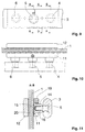
- FIG. 7 shows a first embodiment, at which the horizontal support 3 one essentially rectangular cross section with rounded top and bottom Has guide surfaces.
- the guide rollers 4, 5 and 6 are each concave, so that a lateral guide of the horizontal beam is guaranteed.
- How, for example 7 is on the rollers 4, 5 and 6th each integrally attached to a shaft 15, which by means of a bearing 16 (needle bearing) rotatable in a bearing housing 14 is stored.
- the bearing housing 14 is through a recess the carrier plate 11 inserted and is by the Screwing the support plate 11 held.
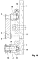
- a variant too this embodiment shown in FIG. 7 results 15 and 16.
- There the guide roller is by means of of the bearing 16 mounted directly on a fixed axis 17.
- the axis 17 is by means of a nut 18 with the Bearing housing 14 screwed (see also Fig. 15).
- FIGS. 5 and 6 show in partial section - like FIGS. 5 and 6 - The adjustable arrangement of the second guide roller 5.
- the bearing housing 14 is eccentric Provided flange 20, which in a recess of the support plate 11 is rotatable (see in particular also Fig. 5 and 6).
- the respective screws are fixed by means of the screws 19 Eccentric position of the bearing housing 14. On this Way, it is possible to adjust the guide roller 5 to to ensure a play-free guidance of the carrier 3.
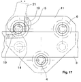
- the horizontal support 3 has in this embodiment a C-shaped cross-section (see in particular 11 to 14), in the interior of which the guide rollers 4, 5 and 6 are arranged.
- the guide rollers 4, 5 and 6 are arranged.
- the inner edges of the carrier 3 crowned, so that a side guide by means of the concave guide rollers 4, 5 and 6 is guaranteed.
- the guide rollers accordingly by means of a bearing housing 14 mounted on the support plate 11.
- the one shown in Fig. 11 The adjustability of the second guide roller 5 is analog Way of the adjustability shown in FIG. 8, an eccentric flange 20 is also provided here. How 17, the eccentric Flange with side contact surfaces for an open-end wrench 21 be provided so that it is easily possible after loosening the screws 19, the bearing housing 14 twist accordingly to adjust the second Ensure guide roller 5.
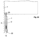
- FIG. 19 to 22 is a simplified plan view Embodiment shown, in which the invention Shower partition, for example as a bathtub partition is installed. From the sequence of FIGS. 19 to 22 results the opening process. Fig. 19 shows the closed Status. An end seal 22 is either against a wall of a building or an additional partition or something similar. By pushing back the second one Cutting disc 2 results in the state shown in FIG. 20. The first cutting disc can now be used together with the second cutting disc can be pivoted about an axis 23, either outside or inside.
- FIG. 23 to 26 show the situation in plan view in a corner shower, in which two according to the invention Shower enclosures are provided.
- 23 shows the completely closed condition.
- Fig. 24 state shown. It is now possible to get the first Swivel cutting discs either outwards or inwards, to ensure free access to the shower tray.
- the pivoting takes place about the axes of rotation 23.
- FIGS. 27 and 28 show an embodiment of an inventive Hinged hinge 10.
- This includes one Bearing block 24, which is in one piece with a mounting plate 25 is provided, which in turn on the wall 7 of the building can be screwed.
- Hinge strap 10 designed as a pendulum.
- bracket 24 is not on a single mounting plate 25, but on a continuous rail 28 attached and itself is also continuously formed (see Fig. 4).
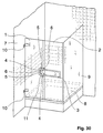
- FIG. 30 shows, analogously to the illustration in FIG. 1, a Corner shower.
- the two carriers 3 In contrast to the configuration according to FIG. 1 are the two carriers 3 at a smaller distance from each other arranged, for example 15 to 20 cm. they are integrally connected to a closed frame.
- the leadership roles 4, 5 and 6 are each, analogous to the embodiment 1, assigned to the upper and lower supports, however, all roles 4, 5 and 6 are on a common one Carrier plate stored.
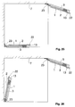
- Figures 31 and 32 show, analogously to Figures 2 and 3 a further embodiment variant of the invention.
- the embodiment of the Figures 31 and 32 for the two together like a frame connected carrier 3 only two upper guide rollers 5 and 6 and a lower guide roller 4.
- This construction is shown again in an enlarged view in FIG. 39. It is understood that the horizontal distance of the two guide rollers 5, 6 is correspondingly variable in order to avoid lateral tilting of the second cutting disc.
- FIG. 33 which is analogous to FIG. 4, shows again a support structure according to the embodiment 30.
- Figures 34 to 37 each show variants of the carrier.
- Fig. 34 all corner areas are with large radii provided, while the embodiment of FIG. 35 a shows rectangular shape.
- FIG. 36 there is also a Provided web, which has an additional grip area 29 forms.
- 37 shows a further exemplary embodiment, in which a plate-like basic shape with a plurality of recesses 30 is used.
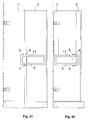
- Figures 40 and 41 show a schematic representation two further side views of a support structure according to the invention.
- the Carrier plate upper guide rollers 5 and 6 arranged, similar the previously described embodiments.
- two lower rollers 4 are provided for these, which provides additional support for the lower Guide area 3 of the horizontal beam.
- the Height of the frame-shaped horizontal shown in FIG. 40 Carrier can be 80 mm, for example. Even with heavy ones Cutting discs or glass doors ensure that do not tilt and do not tilt. A jamming of the horizontal carrier 3 is thus reliably avoided.
- Fig. 41 shows that one end of the horizontal, frame-shaped support 3 is open can be. It is understood that the U-shaped support also can be used rotated by 180 °.
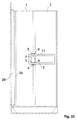
- Carrier 3 shows a further exemplary embodiment of the invention Carrier 3. This is designed like a frame, the two guide rollers 4 and 5 in the interior of the carrier 3 are arranged.
- the interior can be in its Height slit-shaped and dimensioned so that it is only slightly larger than the diameter of the guide rollers 4, 5.
- the invention is not based on the exemplary embodiments shown limited, rather arise within the scope of the invention diverse modification and modification options. These lie in both the dimensioning and design of the carrier, as well as in the displaceability and Swiveling of both the first cutting disc as well the second cutting disc.
- the shower partition according to the invention is thus a sliding door, to the corner entrance, as a revolving door and can also be used as a folding door.
- the invention can thus universal for all types of showers or bathrooms, with Side entry or corner entry can be used. In summary, the following can be stated:
- the invention relates to a shower enclosure with at least a vertically mounted frameless first cutting disc 1, on which in a plane parallel to the plane of first cutting disc 1 slidably a second cutting disc 2 is held, characterized in that on the second Cutting disc 2 in a plane parallel to this and from the second cutting disc 2 spaced at least one horizontal Carrier 3 is attached, which is longitudinally displaceable by means of at least two guide rollers 4, 5 on the first Cutting disc 1 is mounted.
Landscapes
- Health & Medical Sciences (AREA)
- Public Health (AREA)
- Epidemiology (AREA)
- General Health & Medical Sciences (AREA)
- Bathtubs, Showers, And Their Attachments (AREA)
- Support Devices For Sliding Doors (AREA)
- Percussion Or Vibration Massage (AREA)
- Massaging Devices (AREA)
Applications Claiming Priority (2)
| Application Number | Priority Date | Filing Date | Title |
|---|---|---|---|
| DE19742139A DE19742139C2 (de) | 1997-09-24 | 1997-09-24 | Duschabtrennung |
| DE19742139 | 1997-09-24 |
Publications (1)
| Publication Number | Publication Date |
|---|---|
| EP0904720A1 true EP0904720A1 (fr) | 1999-03-31 |
Family
ID=7843472
Family Applications (1)
| Application Number | Title | Priority Date | Filing Date |
|---|---|---|---|
| EP97121265A Withdrawn EP0904720A1 (fr) | 1997-09-24 | 1997-12-03 | Cloison de douche |
Country Status (4)
| Country | Link |
|---|---|
| US (1) | US5911519A (fr) |
| EP (1) | EP0904720A1 (fr) |
| CA (1) | CA2225874A1 (fr) |
| DE (2) | DE19742139C2 (fr) |
Families Citing this family (19)
| Publication number | Priority date | Publication date | Assignee | Title |
|---|---|---|---|---|
| EP1201840B1 (fr) * | 2000-10-26 | 2008-12-10 | Andreas Oswald GmbH | Système à parois de séparation sur pieds |
| US6966816B2 (en) * | 2001-05-02 | 2005-11-22 | Applied Materials, Inc. | Integrated endpoint detection system with optical and eddy current monitoring |
| US6811466B1 (en) * | 2001-12-28 | 2004-11-02 | Applied Materials, Inc. | System and method for in-line metal profile measurement |
| US6990771B2 (en) * | 2002-09-18 | 2006-01-31 | Architectural Automations, L.L.C. | Inertial control system for opening and closing multiple sliding doors in a common direction |
| DE20304389U1 (de) | 2003-03-18 | 2003-06-05 | Altura Leiden Holding B.V., Vianen | Trennwand |
| GB2422539A (en) * | 2005-01-29 | 2006-08-02 | Majestic Shower Company Ltd | Shower enclosure |
| US8061534B2 (en) * | 2006-09-08 | 2011-11-22 | Leviton Manufacturing Co., Inc. | Equipment rack panel system and method |
| JP4189426B2 (ja) * | 2007-01-31 | 2008-12-03 | 株式会社東芝 | センサ装置、及びこれを用いた携帯通信端末及び電子機器 |
| USD632268S1 (en) | 2007-09-07 | 2011-02-08 | Leviton Manufacturing Co., Inc. | Equipment rack panel |
| US20130097935A1 (en) * | 2011-10-24 | 2013-04-25 | C.R. Laurence Company, Inc. | Sliding shower door assembly |
| USD739210S1 (en) | 2013-05-31 | 2015-09-22 | Maax Bath Inc. | Shower panel guide |
| USD740104S1 (en) | 2013-05-31 | 2015-10-06 | Maax Bath Inc. | Shower panel guide |
| CN103498577B (zh) * | 2013-09-30 | 2016-06-01 | 宁波善意电器有限公司 | 一种低盆淋浴房 |
| CN105275228B (zh) * | 2013-09-30 | 2018-10-19 | 金少平 | 一种淋浴房 |
| EP2868247A1 (fr) * | 2013-10-31 | 2015-05-06 | Kohler Co. | Ensemble de porte de douche |
| US10455990B2 (en) * | 2016-01-15 | 2019-10-29 | Gus's Kitchen & Bath Limited | Trackless, frameless bi-fold doors for use with a shower or bathtub |
| US10278547B2 (en) * | 2016-05-02 | 2019-05-07 | Maax Bath Inc. | Door assembly for a bathing enclosure |
| CN105840050B (zh) * | 2016-05-12 | 2018-01-19 | 福建西河卫浴科技有限公司 | 一种滑轨式低障碍联动淋浴房及安装方法 |
| WO2019173755A1 (fr) * | 2018-03-08 | 2019-09-12 | Inlay Door Systems LLC | Système de porte coulissante permettant une fermeture en ligne et pouvant être utilisé avec des ouvertures de coin |
Citations (4)
| Publication number | Priority date | Publication date | Assignee | Title |
|---|---|---|---|---|
| DE3105277A1 (de) * | 1981-02-13 | 1982-08-26 | Paul-Jean 7816 Münstertal Munch | "trennwand fuer eine dusche" |
| FR2683138A1 (fr) * | 1991-11-05 | 1993-05-07 | Algue Sa | Ecran de douche ou de baignoire, muni d'un bras telescopique sur lequel sont fixees trois vitres, dont le deplacement de deux d'entre elles est proportionnel, l'une par rapport a l'autre. |
| DE4308413A1 (de) * | 1993-03-17 | 1994-09-22 | Paul Jean Munch | Trennwand für Dusche mit einer Schiebetüre |
| DE29618205U1 (de) * | 1996-10-21 | 1997-02-13 | Dorma Gmbh + Co. Kg, 58256 Ennepetal | Duschabtrennung |
Family Cites Families (6)
| Publication number | Priority date | Publication date | Assignee | Title |
|---|---|---|---|---|
| US4611436A (en) * | 1985-06-17 | 1986-09-16 | Southern Door Company | Sliding door assembly |
| US4785485A (en) * | 1987-01-20 | 1988-11-22 | Keller Industries | Three panel bath enclosure |
| DE3725543C2 (de) * | 1987-08-01 | 1996-10-02 | Hoesch Metall & Kunststoffwerk | Duschabtrennung |
| DE3907986A1 (de) * | 1989-03-11 | 1990-09-13 | Hoesch Metall & Kunststoffwerk | Duschabtrennung mit verschiebbare wandteil |
| US5079872A (en) * | 1990-09-20 | 1992-01-14 | Sterling Plumbing Group, Inc. | Transom assembly for bathing enclosure or the like |
| DE4205784C2 (de) * | 1991-03-28 | 1994-05-11 | Schulte Duschkabinen | Duschabtrennung mit Linearauszug |
-
1997
- 1997-09-24 DE DE19742139A patent/DE19742139C2/de not_active Expired - Fee Related
- 1997-11-24 DE DE29720832U patent/DE29720832U1/de not_active Expired - Lifetime
- 1997-12-03 EP EP97121265A patent/EP0904720A1/fr not_active Withdrawn
- 1997-12-23 US US08/997,159 patent/US5911519A/en not_active Expired - Fee Related
- 1997-12-29 CA CA002225874A patent/CA2225874A1/fr not_active Abandoned
Patent Citations (4)
| Publication number | Priority date | Publication date | Assignee | Title |
|---|---|---|---|---|
| DE3105277A1 (de) * | 1981-02-13 | 1982-08-26 | Paul-Jean 7816 Münstertal Munch | "trennwand fuer eine dusche" |
| FR2683138A1 (fr) * | 1991-11-05 | 1993-05-07 | Algue Sa | Ecran de douche ou de baignoire, muni d'un bras telescopique sur lequel sont fixees trois vitres, dont le deplacement de deux d'entre elles est proportionnel, l'une par rapport a l'autre. |
| DE4308413A1 (de) * | 1993-03-17 | 1994-09-22 | Paul Jean Munch | Trennwand für Dusche mit einer Schiebetüre |
| DE29618205U1 (de) * | 1996-10-21 | 1997-02-13 | Dorma Gmbh + Co. Kg, 58256 Ennepetal | Duschabtrennung |
Also Published As
| Publication number | Publication date |
|---|---|
| CA2225874A1 (fr) | 1999-03-24 |
| DE19742139C2 (de) | 2000-07-06 |
| US5911519A (en) | 1999-06-15 |
| DE29720832U1 (de) | 1999-01-28 |
| DE19742139A1 (de) | 1999-03-25 |
Similar Documents
| Publication | Publication Date | Title |
|---|---|---|
| EP0904720A1 (fr) | Cloison de douche | |
| EP0295513B1 (fr) | Cloison, en particulier pour douche en coin ou circulaire | |
| EP1296011B1 (fr) | Couvercle pliant à deux panneaux | |
| DE3343066A1 (de) | Moebel mit hoehen- und/oder neigungsverstellbarer tischplatte | |
| EP0119514B1 (fr) | Cloison de séparation | |
| DE69125716T2 (de) | Badewannenschirm | |
| DE3800445C2 (de) | Führung für eine Schiebetür od. dgl., insbesondere bei Dusch- oder Badewannenabtrennungen | |
| EP3834663B1 (fr) | Tiroir, en particulier tiroir de placard de cuisine | |
| DE3639990A1 (de) | Trennwand fuer dusche | |
| EP0379965B1 (fr) | Poubelle | |
| EP0484932A1 (fr) | Cloison de douche | |
| DE202007003727U1 (de) | Schiebetür mit versenkter Teleskop-Führungsschiene | |
| DE19911703C1 (de) | Duschabtrennung | |
| DE2735248C2 (de) | Schubladenführung | |
| EP0779230B1 (fr) | Récipient à ordures destiné à être intégré dans un meuble | |
| DD294409A5 (de) | Krankenhaus-nachttisch | |
| DE202005003595U1 (de) | Tisch | |
| DE102005003394B4 (de) | Führungssystem, insbesondere für Dusch- und Badewannenabtrennungen | |
| EP0477578B1 (fr) | Cloison | |
| DE2418193A1 (de) | In einen schrank einschiebbare schwenktuer | |
| DE3800882A1 (de) | Trennwand, insbesondere fuer eine eck- oder runddusche | |
| DE2929405C2 (de) | Verstellbare Aufhängevorrichtung für ein an einer Wand befestigbares Möbelstück, beispielsweise Wandhängeschrank | |
| DE3911187A1 (de) | Hebekippfenster | |
| EP2492426A2 (fr) | Système de porte coulissante et cabine de douche comportant le système de porte coulissante | |
| EP0115604B1 (fr) | Système à éléments coulissants |
Legal Events
| Date | Code | Title | Description |
|---|---|---|---|
| PUAI | Public reference made under article 153(3) epc to a published international application that has entered the european phase |
Free format text: ORIGINAL CODE: 0009012 |
|
| AK | Designated contracting states |
Kind code of ref document: A1 Designated state(s): AT BE CH DE DK ES FI FR GB GR IE IT LI LU MC NL PT SE |
|
| AX | Request for extension of the european patent |
Free format text: AL;LT;LV;MK;RO;SI |
|
| AKX | Designation fees paid | ||
| STAA | Information on the status of an ep patent application or granted ep patent |
Free format text: STATUS: THE APPLICATION IS DEEMED TO BE WITHDRAWN |
|
| 18D | Application deemed to be withdrawn |
Effective date: 19991001 |
|
| REG | Reference to a national code |
Ref country code: DE Ref legal event code: 8566 |