EP0904793B1 - Distal volume monitoring - Google Patents
Distal volume monitoring Download PDFInfo
- Publication number
- EP0904793B1 EP0904793B1 EP98307698A EP98307698A EP0904793B1 EP 0904793 B1 EP0904793 B1 EP 0904793B1 EP 98307698 A EP98307698 A EP 98307698A EP 98307698 A EP98307698 A EP 98307698A EP 0904793 B1 EP0904793 B1 EP 0904793B1
- Authority
- EP
- European Patent Office
- Prior art keywords
- patient
- flow
- gas
- during
- fresh gas
- Prior art date
- Legal status (The legal status is an assumption and is not a legal conclusion. Google has not performed a legal analysis and makes no representation as to the accuracy of the status listed.)
- Expired - Lifetime
Links
- 238000012544 monitoring process Methods 0.000 title description 7
- 230000029058 respiratory gaseous exchange Effects 0.000 claims description 57
- 230000003434 inspiratory effect Effects 0.000 claims description 14
- 238000005259 measurement Methods 0.000 claims 2
- 239000007789 gas Substances 0.000 description 65
- FQXXSQDCDRQNQE-UHFFFAOYSA-N markiertes Thebain Natural products COC1=CC=C2C(N(CC3)C)CC4=CC=C(OC)C5=C4C23C1O5 FQXXSQDCDRQNQE-UHFFFAOYSA-N 0.000 description 13
- QKQQEIVDLRUZRP-UHFFFAOYSA-N northebaine Natural products COC1=CC=C2C(NCC3)CC4=CC=C(OC)C5=C4C23C1O5 QKQQEIVDLRUZRP-UHFFFAOYSA-N 0.000 description 13
- 206010002091 Anaesthesia Diseases 0.000 description 9
- 230000037005 anaesthesia Effects 0.000 description 9
- 230000001815 facial effect Effects 0.000 description 3
- 230000003444 anaesthetic effect Effects 0.000 description 2
- 238000001356 surgical procedure Methods 0.000 description 2
- 239000006096 absorbing agent Substances 0.000 description 1
- 238000001949 anaesthesia Methods 0.000 description 1
- 208000008784 apnea Diseases 0.000 description 1
- 230000000694 effects Effects 0.000 description 1
- 239000003193 general anesthetic agent Substances 0.000 description 1
- 230000010354 integration Effects 0.000 description 1
- 238000009423 ventilation Methods 0.000 description 1
Images
Classifications
-
- A—HUMAN NECESSITIES
- A61—MEDICAL OR VETERINARY SCIENCE; HYGIENE
- A61M—DEVICES FOR INTRODUCING MEDIA INTO, OR ONTO, THE BODY; DEVICES FOR TRANSDUCING BODY MEDIA OR FOR TAKING MEDIA FROM THE BODY; DEVICES FOR PRODUCING OR ENDING SLEEP OR STUPOR
- A61M16/00—Devices for influencing the respiratory system of patients by gas treatment, e.g. ventilators; Tracheal tubes
- A61M16/08—Bellows; Connecting tubes ; Water traps; Patient circuits
-
- A—HUMAN NECESSITIES
- A61—MEDICAL OR VETERINARY SCIENCE; HYGIENE
- A61M—DEVICES FOR INTRODUCING MEDIA INTO, OR ONTO, THE BODY; DEVICES FOR TRANSDUCING BODY MEDIA OR FOR TAKING MEDIA FROM THE BODY; DEVICES FOR PRODUCING OR ENDING SLEEP OR STUPOR
- A61M16/00—Devices for influencing the respiratory system of patients by gas treatment, e.g. ventilators; Tracheal tubes
- A61M16/0057—Pumps therefor
- A61M16/0081—Bag or bellow in a bottle
-
- A—HUMAN NECESSITIES
- A61—MEDICAL OR VETERINARY SCIENCE; HYGIENE
- A61B—DIAGNOSIS; SURGERY; IDENTIFICATION
- A61B5/00—Measuring for diagnostic purposes; Identification of persons
- A61B5/08—Measuring devices for evaluating the respiratory organs
- A61B5/087—Measuring breath flow
-
- A—HUMAN NECESSITIES
- A61—MEDICAL OR VETERINARY SCIENCE; HYGIENE
- A61M—DEVICES FOR INTRODUCING MEDIA INTO, OR ONTO, THE BODY; DEVICES FOR TRANSDUCING BODY MEDIA OR FOR TAKING MEDIA FROM THE BODY; DEVICES FOR PRODUCING OR ENDING SLEEP OR STUPOR
- A61M16/00—Devices for influencing the respiratory system of patients by gas treatment, e.g. ventilators; Tracheal tubes
- A61M16/0057—Pumps therefor
- A61M16/0078—Breathing bags
-
- A—HUMAN NECESSITIES
- A61—MEDICAL OR VETERINARY SCIENCE; HYGIENE
- A61M—DEVICES FOR INTRODUCING MEDIA INTO, OR ONTO, THE BODY; DEVICES FOR TRANSDUCING BODY MEDIA OR FOR TAKING MEDIA FROM THE BODY; DEVICES FOR PRODUCING OR ENDING SLEEP OR STUPOR
- A61M16/00—Devices for influencing the respiratory system of patients by gas treatment, e.g. ventilators; Tracheal tubes
- A61M16/01—Devices for influencing the respiratory system of patients by gas treatment, e.g. ventilators; Tracheal tubes specially adapted for anaesthetising
-
- A—HUMAN NECESSITIES
- A61—MEDICAL OR VETERINARY SCIENCE; HYGIENE
- A61M—DEVICES FOR INTRODUCING MEDIA INTO, OR ONTO, THE BODY; DEVICES FOR TRANSDUCING BODY MEDIA OR FOR TAKING MEDIA FROM THE BODY; DEVICES FOR PRODUCING OR ENDING SLEEP OR STUPOR
- A61M16/00—Devices for influencing the respiratory system of patients by gas treatment, e.g. ventilators; Tracheal tubes
- A61M16/22—Carbon dioxide-absorbing devices ; Other means for removing carbon dioxide
-
- A—HUMAN NECESSITIES
- A61—MEDICAL OR VETERINARY SCIENCE; HYGIENE
- A61M—DEVICES FOR INTRODUCING MEDIA INTO, OR ONTO, THE BODY; DEVICES FOR TRANSDUCING BODY MEDIA OR FOR TAKING MEDIA FROM THE BODY; DEVICES FOR PRODUCING OR ENDING SLEEP OR STUPOR
- A61M16/00—Devices for influencing the respiratory system of patients by gas treatment, e.g. ventilators; Tracheal tubes
- A61M16/0003—Accessories therefor, e.g. sensors, vibrators, negative pressure
- A61M2016/003—Accessories therefor, e.g. sensors, vibrators, negative pressure with a flowmeter
- A61M2016/0033—Accessories therefor, e.g. sensors, vibrators, negative pressure with a flowmeter electrical
- A61M2016/0036—Accessories therefor, e.g. sensors, vibrators, negative pressure with a flowmeter electrical in the breathing tube and used in both inspiratory and expiratory phase
Definitions
- the present invention relates to the monitoring of volume to a patient during anesthesia, and more particularly, to a system that allows the monitoring of the tidal volume to the patient by the use of flow sensors that are located at the machine or distal end of the patient breathing circuit.
- anesthesia systems are utilized in operating rooms and comprise various equipment necessary to anesthetize the patient and maintain the patient in that state until the operation is completed and it is possible to terminate the introduction of the anesthetic agent.
- Such systems include various pressure regulators, flow control devices, gas mixing devices and vaporizers to provide an anesthetic laden stream of gas to the patient.
- the patient is connected to the system by means of a face mask or other device and which interfaces with the anesthesia system by means of a patient breathing circuit.
- the system provides the anesthetic laden gas to the patient during an inspiratory cycle and receives the patient's exhaled gases during an expiratory cycle.
- the present systems provide one or more flow sensors that monitor flow at various times through the patient breathing circuit and then integrate that flow with respect to a specific time to arrive at the tidal volume.
- the flow sensor that monitors the flow is located in the expiration side of the breathing circuit and the expiration cycle time is used to determine the tidal volume.
- the flow sensor or flow sensors are conveniently located at the distal end of the patient breathing circuit in the inspiratory or expiratory limbs, that is, the end of the patient breathing circuit that is affixed to the anesthesia machine. Such position is convenient and is possible due to the path of flow within the circle breathing system since it is basically a closed system and the flow of gas follows the direction of a circle with fresh gas added to the system.
- the distal end of a patent breathing circuit is considered to be the end of the patient breathing circuit that is attached to the anesthesia machine and the proximal end of the patient breathing circuit is considered to be that end that is attached to the patient administration device, that is the face mask, endotracheal tube or the like.
- the patient basically rebreathes some of the exhaled gas from the large central tube while receiving fresh gas through a separate tube that either lies coaxially within the large central tube as in the Bain circuit or through a separate tube that is outside but parallels the large central tube (Mapleson D circuit), both of which introduce the fresh gas to the system at or near the proximal end of the large central tube.
- the flow sensor must, therefore, be positioned at the proximal end of the patient breathing circuit, that is, at the end of the circuit that is connected to the patient so that it reads only the gases actually exhaled by the patient.
- the difficulty with such arrangement is that such circuits are commonly used for infants and the positioning of the flow sensor at the end of the patient circuit connected to the patient adds additional and undesirable dead space to the circuit and further adds additional bulk to a device that is affixed to the patient.
- the location of the flow sensor adjacent the patient also introduces additional connections into the patient breathing circuit at a point where accidental disconnects frequently occur.
- Each additional connection at the proximal end of the circuit increases the possibility of leakage or disconnection.
- the additional clutter to the overall patient breathing circuit and the access to the patient.
- the Bain circuit is used for facial surgery since the single tube reduces the clutter and enhances the access to the patient's face.
- the additional clutter makes facial operations that much more difficult to perform.
- WO86/05992 describes a system for controlling the flow of gas in an anaesthesia system and include a circuit that is equivalent to a Mapleson D circuit in which inspiratory and expiratory gases flow through a single tube and fresh gas is supplied through a further tube. Flow sensors are provided in each tube.
- a system that carries out the monitoring of the tidal volume of gas delivered to the patient through a Bain or Mapleson D circuit or similar circuit and which accurately carries out the monitoring of flow expired from the patient at the machine end or distal end of the patient breathing circuit.
- a further flow sensor is used, also at the distal end of the patient circuit and which monitors the flow in the fresh gas delivered to the patient during the expiratory phase of the ventilation cycle.
- the fresh gas flow information may also be obtained from an electronic mixer or by direct input by the user.
- a processor obtains the data representative of the total expired flow from the patient from a sensor located at the machine end of the patient breathing circuit and also receives the information as to the flow of fresh gas during the expiratory cycle and carries out a subtraction step that reduces the total flow sensed by the flow of the fresh gas during expiration and thus calculates an accurate value of the flow for the patient's expiration. That value, when integrated with respect to the appropriate time during expiration, provides an accurate determination of the patient's tidal volume without having a flow sensor at or near the patient connection.
- an accurate determination can be made of the fresh gas flow during the inspiratory cycle to obtain total gas delivered to the patient for purposes as determining volume apnea.
- the flow in the fresh gas stream can be monitored during the inspiratory cycle can be added to the flow of gas in the main patient breathing circuit also during the inspiratory cycle and determine total flow of gas to the patient.
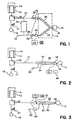
- FIG. 1 there is shown a schematic view of a typical circle patient breathing circuit 10.
- a bellows container 12 encloses a collapsible bellows 14 that provides a positive breath to the patient .
- a ventilator (not shown) forces a controlled amount of a gas into the bellows container 12 to collapse the bellows 14 to force the breathing gas to the patient 16.
- a flexible bag 18 may be used by the clinician so as to manually squeeze the bag and provide that breathing gas to the patient 16 during anesthesia. In either case, there is period that gas is being supplied to the patient, that is, the inspiratory cycle, and a period that the patient is exhaling back into the breathing circuit, that is, the expiratory cycle.
- a bag to ventilator switch 20 allows the clinician to select the mode of delivering that breathing gas, i.e. through use of the powered ventilator or by the manual bagging mode.
- An adjustable pressure limiting valve 21 is also provided that releases gas from the system when a predetermined pressure is exceeded.
- the breathing gas progresses in conduit 22 where it passes through an absorber 24 where the CO 2 from the patient's exhalation is removed and the breathing gas continues through an inlet conduit 26 to the inspiratory limb 28 of the circle patient breathing circuit 10. That gas passes through a check valve 30 to assure the direction of the flow is in the correct direction and a fresh gas inlet 32 is also provided to add the fresh gas to the system and which combines with the gas circulating in conduit 26 to the circle patient breathing circuit 10 to be administered to the patient.
- a patient connection 34 connects to the patient 16 and provides that breathing gas to the patient 16. As the patient exhales, the gas passes through an expiratory limb 36 of the circle patient breathing circuit 10 and passes that exhaled gas through another check valve 38 to be continuously recirculated through the circle patient breathing circuit 10.
- An inspiratory flow sensor 40 is provided to monitor the flow in the inspiratory limb 28 and an expiratory flow sensor 42 likewise monitors the flow in the expiratory limb 36.
- an expiratory flow sensor monitors the flow from the patient and that flow signal is integrated with respect to the time of the expiratory cycle. That integration may be processed by a CPU 43 to arrive at the tidal volume of the gas to the patient 16 and which may be displayed to the clinician at a display 46.
- FIG. 2 there is shown a schematic view of a conventional Bain patient breathing circuit 48.
- the Bain patient breathing circuit 48 comprises some of the same machine components as the circle patient breathing circuit 10 of FIG. 1 and, where applicable, the same numbers have been assigned to those components.
- the difference is in the Bain patient breathing circuit 48 being comprised of a large bore tube 50 that receives the breathing gas from the bellows 14 or the flexible bag 18 for delivery to the patient.
- the fresh gas is provided at a fresh gas inlet 52 and which is then carried in a smaller tubing 54 that is located internal and coaxial to the large bore tube 50 and terminates adjacent the patient connector 56.
- a flow sensor 58 is located at the proximal or patient end of the Bain patient breathing circuit 48 to monitor all of the patients expired gas. If a flow sensor is placed at the distal or machine end of Bain patient breathing circuit 48, it would read high since it would also include the effect of fresh gas that is delivered continuously and therefore would monitor the fresh gas that is provided even during the expiration cycle. That fresh gas has, of course, not been inhaled by the patient so that the flow sensor at the distal or machine end would provide an inaccurate indication of tidal volume to the patient.
- the device adds considerable additional dead space to the overall breathing system and also adds clutter to the patient connector, thereby making facial surgery more difficult.
- the additional dead space is of utmost importance when dealing with pediatric or small infant patients where the flows are considerably small.
- the Mapleson D circuit that is commonly used in patient breathing circuits is very similar to the Bain patient breathing circuit but the small tubing 54 is located external of the large bore tube 50 and runs along that exterior surface and introduces the fresh gas through the patient connector.
- FIG. 3 there is shown a schematic view of a patient breathing circuit having flow sensors located in accordance with the present invention.
- the Bain patient breathing circuit 48 is used as in FIG. 2.
- a fresh gas flow sensor 60 has been positioned in the fresh gas inlet 52 and which thereby monitors the flow of fresh gas to the Bain breathing circuit at all times.
- a further flow sensor 62 is positioned so as to monitor the flow in the large bore tube 50 and which, therefore can monitor the flow from the patient expiration during that cycle.
- both of the flow sensors 60 and 62 are positioned at the distal end of the Bain patient breathing circuit 48.
- the CPU 43 can receive a signal representative of flow of fresh gas to the Bain patient breathing circuit 48 during the patient expiration period and also receive a signal representative of the flow of the gases from the patient at the machine or proximal end of the large bore tube 50.
- the CPU 43 can thus subtract the flow in the fresh gas conduit during that expiration period and from the total flow of gas from the patient during the expiration and arrive at an accurate determination of the flow from the patient, having taken into account, the flow that was introduced during the expiration cycle and which was not inhaled by the patient.
- the information as to the fresh gas flow can be manually obtained from a user input or directly from an electronic mixer.
Landscapes
- Health & Medical Sciences (AREA)
- Emergency Medicine (AREA)
- Pulmonology (AREA)
- Engineering & Computer Science (AREA)
- Anesthesiology (AREA)
- Biomedical Technology (AREA)
- Heart & Thoracic Surgery (AREA)
- Hematology (AREA)
- Life Sciences & Earth Sciences (AREA)
- Animal Behavior & Ethology (AREA)
- General Health & Medical Sciences (AREA)
- Public Health (AREA)
- Veterinary Medicine (AREA)
- Measurement Of The Respiration, Hearing Ability, Form, And Blood Characteristics Of Living Organisms (AREA)
- Measuring And Recording Apparatus For Diagnosis (AREA)
Description
- The present invention relates to the monitoring of volume to a patient during anesthesia, and more particularly, to a system that allows the monitoring of the tidal volume to the patient by the use of flow sensors that are located at the machine or distal end of the patient breathing circuit.
- In general, anesthesia systems are utilized in operating rooms and comprise various equipment necessary to anesthetize the patient and maintain the patient in that state until the operation is completed and it is possible to terminate the introduction of the anesthetic agent. Such systems include various pressure regulators, flow control devices, gas mixing devices and vaporizers to provide an anesthetic laden stream of gas to the patient. The patient is connected to the system by means of a face mask or other device and which interfaces with the anesthesia system by means of a patient breathing circuit. The system provides the anesthetic laden gas to the patient during an inspiratory cycle and receives the patient's exhaled gases during an expiratory cycle.
- With current anesthesia machines, it is important to monitor the tidal volume of such gas administered to that patient. The present systems provide one or more flow sensors that monitor flow at various times through the patient breathing circuit
and then integrate that flow with respect to a specific time to arrive at the tidal volume. In many such systems, the flow sensor that monitors the flow is located in the
expiration side of the breathing circuit and the expiration cycle time is used to determine the tidal volume. - With the standard circle system breathing circuit, the flow sensor or flow sensors are conveniently located at the distal end of the patient breathing circuit in the inspiratory or expiratory limbs, that is, the end of the patient breathing circuit that is affixed to the anesthesia machine. Such position is convenient and is possible due to the path of flow within the circle breathing system since it is basically a closed system and the flow of gas follows the direction of a circle with fresh gas added to the system.
- As used herein, the distal end of a patent breathing circuit is considered to be the end of the patient breathing circuit that is attached to the anesthesia machine and the proximal end of the patient breathing circuit is considered to be that end that is attached to the patient administration device, that is the face mask, endotracheal tube or the like.
- A problem arises, however, with the use of a Bain breathing circuit or Mapleson D circuit where a large central tube connects the anesthesia machine with the patient and there is a continual to-fro pattern of flow within that tube. As such, the patient basically rebreathes some of the exhaled gas from the large central tube while receiving fresh gas through a separate tube that either lies coaxially within the large central tube as in the Bain circuit or through a separate tube that is outside but parallels the large central tube (Mapleson D circuit), both of which introduce the fresh gas to the system at or near the proximal end of the large central tube. Accordingly, if the tidal volume is measured at the distal end of such circuit, the reading will be inaccurate since the fresh gas flow continues, even during expiration and the flow sensor in the expiratory gas stream will read that additional fresh gas flow administered during the expiratory cycle and thus will read a flow of gas that is not actually administered to the patient.
- In such cases, the flow sensor must, therefore, be positioned at the proximal end of the patient breathing circuit, that is, at the end of the circuit that is connected to the patient so that it reads only the gases actually exhaled by the patient. The difficulty with such arrangement is that such circuits are commonly used for infants and the positioning of the flow sensor at the end of the patient circuit connected to the patient adds additional and undesirable dead space to the circuit and further adds additional bulk to a device that is affixed to the patient.
- Further, the location of the flow sensor adjacent the patient also introduces additional connections into the patient breathing circuit at a point where accidental disconnects frequently occur. Each additional connection at the proximal end of the circuit increases the possibility of leakage or disconnection.
- As further problem of having the flow sensor at the patient connection is the additional clutter to the overall patient breathing circuit and the access to the patient. Often, the Bain circuit is used for facial surgery since the single tube reduces the clutter and enhances the access to the patient's face. By adding the proximal sensor with the added tubing, wiring and the like the additional clutter makes facial operations that much more difficult to perform.
- Accordingly, it would be advantageous to carry out the monitoring of the tidal volume of the patient at the distal end of the patient circuit even when the circuit is of the type that is of the Bain and Mapleson D circuit type with a large tube to the patient with the fresh gas provided by a separate tubing to that patient.
- WO86/05992 describes a system for controlling the flow of gas in an anaesthesia system and include a circuit that is equivalent to a Mapleson D circuit in which inspiratory and expiratory gases flow through a single tube and fresh gas is supplied through a further tube. Flow sensors are provided in each tube.
- The present invention is as set out in the accompanying claims.
- In accordance with the present invention, a system is provided that carries out the monitoring of the tidal volume of gas delivered to the patient through a Bain or Mapleson D circuit or similar circuit and which accurately carries out the monitoring of flow expired from the patient at the machine end or distal end of the patient breathing circuit.
- In carrying out the present invention, a further flow sensor is used, also at the distal end of the patient circuit and which monitors the flow in the fresh gas delivered to the patient during the expiratory phase of the ventilation cycle. Alternatively, the fresh gas flow information may also be obtained from an electronic mixer or by direct input by the user. A processor obtains the data representative of the total expired flow from the patient from a sensor located at the machine end of the patient breathing circuit and also receives the information as to the flow of fresh gas during the expiratory cycle and carries out a subtraction step that reduces the total flow sensed by the flow of the fresh gas during expiration and thus calculates an accurate value of the flow for the patient's expiration. That value, when integrated with respect to the appropriate time during expiration, provides an accurate determination of the patient's tidal volume without having a flow sensor at or near the patient connection.
- As a further use of the flow sensor in the fresh gas stream, an accurate determination can be made of the fresh gas flow during the inspiratory cycle to obtain total gas delivered to the patient for purposes as determining volume apnea. In such case, the flow in the fresh gas stream can be monitored during the inspiratory cycle can be added to the flow of gas in the main patient breathing circuit also during the inspiratory cycle and determine total flow of gas to the patient.
-
- FIG. 1 is schematic view of a circle patient breathing circuit showing the typical location of the flow sensors used to determine tidal volume;
- FIG. 2 is a schematic view of a Bain circuit showing the proximal flow sensor typically used with that breathing circuit; and
- FIG. 3 is a schematic view of a Bain patient breathing circuit showing the location and use of flow sensors used to carry out the present invention.
- Referring now to FIG. 1, there is shown a schematic view of a typical circle
patient breathing circuit 10. As is conventional in that circuit, abellows container 12 encloses acollapsible bellows 14 that provides a positive breath to the patient . As is known, however, a ventilator (not shown) forces a controlled amount of a gas into thebellows container 12 to collapse thebellows 14 to force the breathing gas to thepatient 16. Alternatively, aflexible bag 18 may be used by the clinician so as to manually squeeze the bag and provide that breathing gas to thepatient 16 during anesthesia. In either case, there is period that gas is being supplied to the patient, that is, the inspiratory cycle, and a period that the patient is exhaling back into the breathing circuit, that is, the expiratory cycle. - A bag to
ventilator switch 20 allows the clinician to select the mode of delivering that breathing gas, i.e. through use of the powered ventilator or by the manual bagging mode. An adjustablepressure limiting valve 21 is also provided that releases gas from the system when a predetermined pressure is exceeded. - In either case, the breathing gas progresses in
conduit 22 where it passes through anabsorber 24 where the CO2 from the patient's exhalation is removed and the breathing gas continues through aninlet conduit 26 to theinspiratory limb 28 of the circlepatient breathing circuit 10. That gas passes through acheck valve 30 to assure the direction of the flow is in the correct direction and afresh gas inlet 32 is also provided to add the fresh gas to the system and which combines with the gas circulating inconduit 26 to the circlepatient breathing circuit 10 to be administered to the patient. - A
patient connection 34 connects to thepatient 16 and provides that breathing gas to thepatient 16. As the patient exhales, the gas passes through anexpiratory limb 36 of the circlepatient breathing circuit 10 and passes that exhaled gas through anothercheck valve 38 to be continuously recirculated through the circlepatient breathing circuit 10. - An inspiratory flow sensor 40 is provided to monitor the flow in the
inspiratory limb 28 and anexpiratory flow sensor 42 likewise monitors the flow in theexpiratory limb 36. In some systems, only one flow sensor may be used to determine the flow in patient circuit and generally, an expiratory flow sensor monitors the flow from the patient and that flow signal is integrated with respect to the time of the expiratory cycle. That integration may be processed by aCPU 43 to arrive at the tidal volume of the gas to thepatient 16 and which may be displayed to the clinician at adisplay 46. - Turning now to FIG. 2, there is shown a schematic view of a conventional Bain
patient breathing circuit 48. The Bainpatient breathing circuit 48 comprises some of the same machine components as the circlepatient breathing circuit 10 of FIG. 1 and, where applicable, the same numbers have been assigned to those components. The difference is in the Bainpatient breathing circuit 48 being comprised of alarge bore tube 50 that receives the breathing gas from thebellows 14 or theflexible bag 18 for delivery to the patient. As can be seen, the fresh gas is provided at afresh gas inlet 52 and which is then carried in asmaller tubing 54 that is located internal and coaxial to thelarge bore tube 50 and terminates adjacent thepatient connector 56. As can thus be seen, as the patient exhales and inhales, the breathing gas moves to and fro within thelarge bore tube 50 and the patient inhales some of the gas from thelarge bore tube 50 and fresh gas is provided continuously by thesmall tubing 54 to thepatient 16. Accordingly, to determine the tidal volume, aflow sensor 58 is located at the proximal or patient end of the Bainpatient breathing circuit 48 to monitor all of the patients expired gas. If a flow sensor is placed at the distal or machine end of Bainpatient breathing circuit 48, it would read high since it would also include the effect of fresh gas that is delivered continuously and therefore would monitor the fresh gas that is provided even during the expiration cycle. That fresh gas has, of course, not been inhaled by the patient so that the flow sensor at the distal or machine end would provide an inaccurate indication of tidal volume to the patient. - As can also be seen, with the placement of the
flow sensor 58 at the proximal end of the Bainpatient breathing circuit 48, the device adds considerable additional dead space to the overall breathing system and also adds clutter to the patient connector, thereby making facial surgery more difficult. The additional dead space is of utmost importance when dealing with pediatric or small infant patients where the flows are considerably small. It should be noted that the Mapleson D circuit that is commonly used in patient breathing circuits is very similar to the Bain patient breathing circuit but thesmall tubing 54 is located external of thelarge bore tube 50 and runs along that exterior surface and introduces the fresh gas through the patient connector. - Finally, turning now to FIG,. 3, there is shown a schematic view of a patient breathing circuit having flow sensors located in accordance with the present invention. Again, as may be seen, the Bain
patient breathing circuit 48 is used as in FIG. 2. In this case, however, a freshgas flow sensor 60 has been positioned in thefresh gas inlet 52 and which thereby monitors the flow of fresh gas to the Bain breathing circuit at all times. Afurther flow sensor 62 is positioned so as to monitor the flow in thelarge bore tube 50 and which, therefore can monitor the flow from the patient expiration during that cycle. As noted, both of theflow sensors patient breathing circuit 48. - Thus the
CPU 43 can receive a signal representative of flow of fresh gas to the Bainpatient breathing circuit 48 during the patient expiration period and also receive a signal representative of the flow of the gases from the patient at the machine or proximal end of thelarge bore tube 50. TheCPU 43 can thus subtract the flow in the fresh gas conduit during that expiration period and from the total flow of gas from the patient during the expiration and arrive at an accurate determination of the flow from the patient, having taken into account, the flow that was introduced during the expiration cycle and which was not inhaled by the patient. As noted, the information as to the fresh gas flow can be manually obtained from a user input or directly from an electronic mixer. - Accordingly, by integrating that value of flow, an accurate determination of tidal volume can be obtained without having a flow sensor located at the patient or proximal end of the Bain patient breathing circuit.
- While the present invention has been set forth in terms of a specific embodiment, it will be understood that the monitoring system herein disclosed may be modified or altered by the those skilled in the art to other configurations. Accordingly, the invention is to be broadly construed and limited only by the scope of the claims appended hereto.
Claims (6)
- A system for determining the tidal volume of a patient receiving breaths from a breathing means (12-20) during an inspiratory cycle and configured to receive exhalation from the patient during an expiratory cycle, said system comprising
a patient breathing circuit (48) having a main delivery tube (50) having a distal end configured to be connected to a breathing means (12-20) and a proximal end configured to be connected to a patient (16) to communicate between the breathing means (12-20) and the patient (16), a fresh gas delivery tubing (54) configured to be connected to a source of fresh gas to deliver fresh gas from the source of fresh gas to the patient (16),
a first flow sensor (62) configured to determine the flow of gas within said main delivery tube (50), and
a second flow sensor (60) to determine the flow of fresh gas in said tubing (54) during said expiratory cycle,
a processor (43) configured to receive signals from said first and said second flow monitors (62, 60);
characterised in that:the processor (43) is configured:(a) to carry out a subtraction step that subtracts the flow of the fresh gas during expiration sensed by the second sensor from the flow of gas flowing in the main delivery tube (50) during expiration sensed by the first sensor and to thereby calculate a value of the gas flow during the patient's expiration to provide a measurement of the volume of gas expired by the patient and/or(b) to carry out an addition step that adds the flow of gas in the fresh gas delivery tubing (54) during an inspiratory cycle sensed by the second sensor to the flow of gas in the main delivery tube (50) sensed by the first sensor (62) during the inspiratory cycle and thereby determine the total flow of gas to the patient during the inspiratory cycle to provide a measurement of the volume of gas delivered to the patient. - A system as defined in claim 1, wherein the processor is configured to integrate the gas flow value derived from subtraction step (a) with respect to a known time period, e.g. time during expiration, to determine the volume of gas expired by the patient.
- A system as defined in Claim I or claim 2 wherein said first flow sensor (62) is located at the distal end of said main delivery tube (50).
- A system as defined in any of Claims 1 to 3 wherein said fresh gas tubing (54) has a proximal end providing the fresh gas to a patient at or near the proximal end of said main delivery tube (50) and a distal end and wherein said second flow sensor (60) is located at the distal end of said fresh gas tubing (54).
- A system as defined in any of Claims 1 to 4 wherein said patient breathing circuit is a Bain circuit.
- A system as defined in any one of Claims 1 to 4 wherein said patient breathing circuit is a Mapleson D circuit.
Applications Claiming Priority (2)
| Application Number | Priority Date | Filing Date | Title |
|---|---|---|---|
| US08/938,850 US6125848A (en) | 1997-09-26 | 1997-09-26 | Distal volume monitoring |
| US938850 | 1997-09-26 |
Publications (3)
| Publication Number | Publication Date |
|---|---|
| EP0904793A2 EP0904793A2 (en) | 1999-03-31 |
| EP0904793A3 EP0904793A3 (en) | 1999-12-08 |
| EP0904793B1 true EP0904793B1 (en) | 2006-04-26 |
Family
ID=25472067
Family Applications (1)
| Application Number | Title | Priority Date | Filing Date |
|---|---|---|---|
| EP98307698A Expired - Lifetime EP0904793B1 (en) | 1997-09-26 | 1998-09-22 | Distal volume monitoring |
Country Status (2)
| Country | Link |
|---|---|
| US (1) | US6125848A (en) |
| EP (1) | EP0904793B1 (en) |
Families Citing this family (16)
| Publication number | Priority date | Publication date | Assignee | Title |
|---|---|---|---|---|
| DE69725759T2 (en) * | 1997-03-19 | 2004-08-05 | Joseph Arnold Thornhill Fisher | DEVICE FOR REMOVING ANESTHETIC VAPOR FROM A PATIENT AFTER SURGICAL OPERATION |
| FR2804030B1 (en) * | 2000-01-21 | 2003-01-03 | Taema | RESPIRATORY ANESTHESIA APPARATUS WITH AUTOMATIC GAS FLOW MANAGEMENT |
| CA2304292C (en) * | 2000-03-31 | 2009-01-13 | Joseph Fisher | An improved rebreathing circuit to set and stabalize end tidal and arterial pco2 despite varying levels of minute ventilation |
| US7073502B2 (en) * | 2003-01-27 | 2006-07-11 | Instrumentarium Corp. | Manual ventilation system including manual bag filling valve |
| JP4684300B2 (en) | 2005-02-02 | 2011-05-18 | モコン・インコーポレーテッド | Apparatus and method for detecting and reporting the magnitude of a leak in a hermetically sealed package |
| WO2006088542A2 (en) | 2005-02-14 | 2006-08-24 | Mocon, Inc. | Detecting and reporting the location of a leak in hermetically sealed packaging |
| US7252014B1 (en) | 2006-04-17 | 2007-08-07 | Mocon, Inc. | Instrument and method for measuring the volume of a hermetically sealed variable volume and pressure conforming container |
| US7654131B2 (en) | 2006-06-14 | 2010-02-02 | Mocon, Inc. | Instrument for accurately measuring mass flow rate of a fluid pumped from a hermetically sealed container |
| AU2006252044B2 (en) * | 2006-12-13 | 2014-04-03 | Colin Dunlop | Method and apparatus for delivering a fluid to a patient |
| CN101468221B (en) * | 2007-12-29 | 2013-10-23 | 北京谊安医疗系统股份有限公司 | Anaesthetic absorbing loop |
| CN101301503B (en) * | 2008-06-26 | 2010-06-02 | 上海力申科学仪器有限公司 | Automatic calibration method of anesthesia apparatus gas volume |
| CN101934108B (en) * | 2009-07-02 | 2013-08-14 | 北京谊安医疗系统股份有限公司 | Tidal volume detection method and device for anesthesia machine or breathing machine |
| DE102015015441A1 (en) * | 2015-12-02 | 2017-06-08 | Drägerwerk AG & Co. KGaA | Anesthesia ventilation device for automated ventilation and for detecting an operating state with regard to automated ventilation |
| CN109259766A (en) * | 2018-11-16 | 2019-01-25 | 培婴(湖北)医学技术有限公司 | The monitoring device and ventilator of tidal volume |
| CN111990999A (en) * | 2020-09-24 | 2020-11-27 | 苏州大学 | Device and method for real-time monitoring of tidal volume based on simple one-way valve shunt gas |
| CN116782972B (en) * | 2020-12-31 | 2024-11-12 | 深圳迈瑞动物医疗科技股份有限公司 | Respiratory ventilation method, device, anesthesia machine and computer readable storage medium |
Family Cites Families (9)
| Publication number | Priority date | Publication date | Assignee | Title |
|---|---|---|---|---|
| US3856051A (en) * | 1972-02-28 | 1974-12-24 | J Bain | Flexible tube device |
| US3972327A (en) * | 1973-03-22 | 1976-08-03 | Hoffmann-La Roche Inc. | Respirator |
| US3910261A (en) * | 1974-06-11 | 1975-10-07 | Bourns Inc | End-tidal gas analysis apparatus for respirators |
| AU547514B2 (en) * | 1980-09-02 | 1985-10-24 | David Humphrey | Anaesthetic system with waste gas scavenging |
| GB8509413D0 (en) * | 1985-04-12 | 1985-05-15 | Penlon Ltd | Gas flow control apparatus |
| US5107831A (en) * | 1989-06-19 | 1992-04-28 | Bear Medical Systems, Inc. | Ventilator control system using sensed inspiratory flow rate |
| CA2004930C (en) * | 1989-12-08 | 1996-04-02 | John Richard Sikora | Anaesthetic and respirator breathing circuit device |
| US5161525A (en) * | 1990-05-11 | 1992-11-10 | Puritan-Bennett Corporation | System and method for flow triggering of pressure supported ventilation |
| US5315989A (en) * | 1991-12-09 | 1994-05-31 | Boc Health Care, Inc. | Medical ventilator |
-
1997
- 1997-09-26 US US08/938,850 patent/US6125848A/en not_active Expired - Fee Related
-
1998
- 1998-09-22 EP EP98307698A patent/EP0904793B1/en not_active Expired - Lifetime
Also Published As
| Publication number | Publication date |
|---|---|
| US6125848A (en) | 2000-10-03 |
| EP0904793A3 (en) | 1999-12-08 |
| EP0904793A2 (en) | 1999-03-31 |
Similar Documents
| Publication | Publication Date | Title |
|---|---|---|
| EP0904793B1 (en) | Distal volume monitoring | |
| US6571792B1 (en) | Smart modular anesthesia respiratory system | |
| CN109069782B (en) | Anesthesia machine and system | |
| JP3955011B2 (en) | Apparatus and method for non-invasive measurement of cardiac output | |
| EP1001824B1 (en) | Tracheal gas insufflation delivery system for respiration equipment | |
| US6213120B1 (en) | Device and method for determining gas volume and volumetric changes in a ventilator | |
| US4127121A (en) | Oxygen and anesthesia delivery and monitoring device | |
| US7909033B2 (en) | Breathing treatment apparatus | |
| US4502481A (en) | Device for manually ventilating a patient | |
| US6152132A (en) | Inspiratory tube for a ventilator | |
| EP1800707B1 (en) | Integrated ventilator nasal trigger and gas monitoring system | |
| CN101927050B (en) | Branching unit for delivering respiratory gas of a subject | |
| US20110197887A1 (en) | Accessory connection and data synchronication in a ventilator | |
| US20050121033A1 (en) | Respiratory monitoring during gas delivery | |
| JPH11137689A (en) | Ventilator | |
| US8925549B2 (en) | Flow control adapter for performing spirometry and pulmonary function testing | |
| JP2010531685A (en) | Gas mixing device for airway maintenance system | |
| JP2000070370A (en) | Artificial respiratory apparatus | |
| CN103251410A (en) | Apparatus, arrangement and method for analyzing breathing gas | |
| CN102834136A (en) | Compensation for unmeasurable inspiratory flow in a critical care ventilator | |
| EP1409054B1 (en) | Device for isolating bias flow | |
| JPH0390164A (en) | Artificial respiration device for controlling flow rate and pressure in circuit matched with respiration flow rate of patient | |
| JP3020606B2 (en) | Oxygen consumption meter | |
| CN108578854A (en) | A kind of respiratory assistance apparatus | |
| Weled et al. | Measuring exhaled volume with continuous positive airway pressure and intermittent mandatory ventilation: techniques and rationale |
Legal Events
| Date | Code | Title | Description |
|---|---|---|---|
| PUAI | Public reference made under article 153(3) epc to a published international application that has entered the european phase |
Free format text: ORIGINAL CODE: 0009012 |
|
| AK | Designated contracting states |
Kind code of ref document: A2 Designated state(s): ES GB |
|
| AX | Request for extension of the european patent |
Free format text: AL;LT;LV;MK;RO;SI |
|
| RAP1 | Party data changed (applicant data changed or rights of an application transferred) |
Owner name: DATEX-OHMEDA, INC. |
|
| PUAL | Search report despatched |
Free format text: ORIGINAL CODE: 0009013 |
|
| AK | Designated contracting states |
Kind code of ref document: A3 Designated state(s): AT BE CH CY DE DK ES FI FR GB GR IE IT LI LU MC NL PT SE |
|
| AX | Request for extension of the european patent |
Free format text: AL;LT;LV;MK;RO;SI |
|
| RIC1 | Information provided on ipc code assigned before grant |
Free format text: 6A 61M 16/00 A |
|
| 17P | Request for examination filed |
Effective date: 20000608 |
|
| AKX | Designation fees paid |
Free format text: ES GB |
|
| REG | Reference to a national code |
Ref country code: DE Ref legal event code: 8566 |
|
| 17Q | First examination report despatched |
Effective date: 20050127 |
|
| GRAP | Despatch of communication of intention to grant a patent |
Free format text: ORIGINAL CODE: EPIDOSNIGR1 |
|
| GRAS | Grant fee paid |
Free format text: ORIGINAL CODE: EPIDOSNIGR3 |
|
| GRAA | (expected) grant |
Free format text: ORIGINAL CODE: 0009210 |
|
| AK | Designated contracting states |
Kind code of ref document: B1 Designated state(s): ES GB |
|
| REG | Reference to a national code |
Ref country code: GB Ref legal event code: FG4D |
|
| PG25 | Lapsed in a contracting state [announced via postgrant information from national office to epo] |
Ref country code: ES Free format text: LAPSE BECAUSE OF FAILURE TO SUBMIT A TRANSLATION OF THE DESCRIPTION OR TO PAY THE FEE WITHIN THE PRESCRIBED TIME-LIMIT Effective date: 20060806 |
|
| PLBE | No opposition filed within time limit |
Free format text: ORIGINAL CODE: 0009261 |
|
| STAA | Information on the status of an ep patent application or granted ep patent |
Free format text: STATUS: NO OPPOSITION FILED WITHIN TIME LIMIT |
|
| 26N | No opposition filed |
Effective date: 20070129 |
|
| PGFP | Annual fee paid to national office [announced via postgrant information from national office to epo] |
Ref country code: GB Payment date: 20080820 Year of fee payment: 11 |
|
| GBPC | Gb: european patent ceased through non-payment of renewal fee |
Effective date: 20090922 |
|
| PG25 | Lapsed in a contracting state [announced via postgrant information from national office to epo] |
Ref country code: GB Free format text: LAPSE BECAUSE OF NON-PAYMENT OF DUE FEES Effective date: 20090922 |