EP0904863A2 - A device in a wire rolling mill - Google Patents
A device in a wire rolling mill Download PDFInfo
- Publication number
- EP0904863A2 EP0904863A2 EP98850146A EP98850146A EP0904863A2 EP 0904863 A2 EP0904863 A2 EP 0904863A2 EP 98850146 A EP98850146 A EP 98850146A EP 98850146 A EP98850146 A EP 98850146A EP 0904863 A2 EP0904863 A2 EP 0904863A2
- Authority
- EP
- European Patent Office
- Prior art keywords
- spindle
- bearings
- rolling mill
- rolling
- wire rolling
- Prior art date
- Legal status (The legal status is an assumption and is not a legal conclusion. Google has not performed a legal analysis and makes no representation as to the accuracy of the status listed.)
- Withdrawn
Links
Images
Classifications
-
- B—PERFORMING OPERATIONS; TRANSPORTING
- B21—MECHANICAL METAL-WORKING WITHOUT ESSENTIALLY REMOVING MATERIAL; PUNCHING METAL
- B21B—ROLLING OF METAL
- B21B35/00—Drives for metal-rolling mills, e.g. hydraulic drives
- B21B35/02—Drives for metal-rolling mills, e.g. hydraulic drives for continuously-operating mills
- B21B35/04—Drives for metal-rolling mills, e.g. hydraulic drives for continuously-operating mills each stand having its own motor or motors
-
- B—PERFORMING OPERATIONS; TRANSPORTING
- B21—MECHANICAL METAL-WORKING WITHOUT ESSENTIALLY REMOVING MATERIAL; PUNCHING METAL
- B21B—ROLLING OF METAL
- B21B13/00—Metal-rolling stands, i.e. an assembly composed of a stand frame, rolls, and accessories
- B21B13/005—Cantilevered roll stands
-
- B—PERFORMING OPERATIONS; TRANSPORTING
- B21—MECHANICAL METAL-WORKING WITHOUT ESSENTIALLY REMOVING MATERIAL; PUNCHING METAL
- B21B—ROLLING OF METAL
- B21B31/00—Rolling stand structures; Mounting, adjusting, or interchanging rolls, roll mountings, or stand frames
- B21B31/07—Adaptation of roll neck bearings
Definitions
- the present invention refers to wire rolling mills of the type comprising a pair of grooved rolls fixedly attached to the free end of one rotatably driven spindle each and being arranged to be positionable so relative to each other that they between themselves define a rolling gap of adjustable size.
- Wire rolling mills of this type commonly comprises a pair of parallel drive shafts which via transmissions, each incorporating e.g. a bevel gear and a pinion transfers the drive to one of the spindles.
- the pinion thereby is fixedly attached to one of the spindles at the end thereof opposite to the grooved roll and cooperating with the bevel gear for rotating the spindle.
- the purpose of the present invention is to provide a device in a wire rolling mill which obviates the drawbacks of the prior designs, thereby presenting a rolling mill spindle of much simplified design, which is still efficient and makes it possible to design the rolling mill in a very compact manner which minimizes the space requirement.
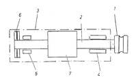
- the grooved roll 1 which shall cooperate with another similar roll (not shown), is firmly attached to the free end of a spindle 2, provided in a housing 3, which is shown in intimated form, and which in any appropriate manner, known per se, is movable (not shown) in such a manner that the rolling gap between two cooperating grooved rolls 1 can be adjusted.
- the spindle 2 is supported in a first and a second radial bearing 4, 5 and in one axial bearing 6, although other bearing combinations can be used.
- bearings 4, 5 and 6 can be used rolling bearings, sliding bearings or magnetic bearings or different combinations of such bearings.
- An electro motor 7 is provided in the housing and the direct output shaft of this electro motor thereby is made integral with the spindle 2.
- Each spindle forming part of the rolling mill is preferably provided with its integrated drive motor, for individual driving of the different rolls, although it is also possible to use a non-driven roll cooperating with the driven roll, in which case the non-driven roll spindle has no integrated motor.
- the electro motor 7 used can be of any well known appropriate type available on the market.
Landscapes
- Engineering & Computer Science (AREA)
- Mechanical Engineering (AREA)
- Metal Rolling (AREA)
- Crushing And Grinding (AREA)
Abstract
Description
Claims (5)
- A device in a wire rolling mill of the type comprising a pair of grooved rolls (7) each one being fixedly attached to the free end of one rotatably supported spindle (2) each and being arranged to be positionable so relative to each other that they between themselves define a rolling gap of adjustable size,
characterized therein
that at least one of said spindles (2) is arranged integrally with the output shaft of an electro motor (7), arranged thereby to drive the spindle (2) directly. - A device as claimed in claim 1,
characterized therein
that the spindle (2) is supported in a combination of bearings (4,5,6) supporting the spindle (2) in radial and axial directions. - A device as claimed in claim 2,
characterized therein
that the bearings (4,5,6) used are rolling bearings, sliding bearings, magnetic bearings and/or different combinations thereof. - A device as claimed in anyone of the preceeding claims,
characterized therein
that each spindle (2) with its integrated motor (7) and supporting means (4,5,6) are enclosed in a bearing housing (3). - A device as claimed in anyone of claims 2 - 4,
characterized therein,
that the radial bearings (4, 5) are supporting the spindle on opposite sides of the electro motor (7).
Applications Claiming Priority (2)
| Application Number | Priority Date | Filing Date | Title |
|---|---|---|---|
| SE9703405 | 1997-09-19 | ||
| SE9703405A SE9703405L (en) | 1997-09-19 | 1997-09-19 | Drive device at a wire rolling mill |
Publications (2)
| Publication Number | Publication Date |
|---|---|
| EP0904863A2 true EP0904863A2 (en) | 1999-03-31 |
| EP0904863A3 EP0904863A3 (en) | 2002-01-16 |
Family
ID=20408323
Family Applications (1)
| Application Number | Title | Priority Date | Filing Date |
|---|---|---|---|
| EP98850146A Withdrawn EP0904863A3 (en) | 1997-09-19 | 1998-09-18 | A device in a wire rolling mill |
Country Status (5)
| Country | Link |
|---|---|
| US (1) | US6138886A (en) |
| EP (1) | EP0904863A3 (en) |
| JP (1) | JP2939256B2 (en) |
| CN (1) | CN1212909A (en) |
| SE (1) | SE9703405L (en) |
Families Citing this family (3)
| Publication number | Priority date | Publication date | Assignee | Title |
|---|---|---|---|---|
| CN100483024C (en) * | 2004-11-09 | 2009-04-29 | 李学霖 | Heat radiation structure of LED lamp |
| CN102091722A (en) * | 2011-01-31 | 2011-06-15 | 中冶赛迪工程技术股份有限公司 | Roller driving method for high-speed rolling and roller device |
| ITUD20120178A1 (en) * | 2012-10-24 | 2014-04-25 | Pmp Ind S P A | "STATION AND LAMINATION PLANT" |
Family Cites Families (19)
| Publication number | Priority date | Publication date | Assignee | Title |
|---|---|---|---|---|
| US1487007A (en) * | 1924-03-18 | Bolling ivi | ||
| US1953165A (en) * | 1930-03-03 | 1934-04-03 | Morgan Construction Co | Rolling mill |
| US1840171A (en) * | 1930-05-31 | 1932-01-05 | Perrett Albert | Leveling device for mill rolls |
| GB999952A (en) * | 1964-05-26 | 1965-07-28 | Vaughn Machinery Co | Bar and wire processing machine |
| FR2048693A5 (en) * | 1969-05-27 | 1971-03-19 | Properzi Ilario | |
| SE381830B (en) * | 1971-11-17 | 1975-12-22 | Morgaardshammar Ab | KIT TO PRE-TENSION A DUOVAL COUPLE FOR HOT OR COLD ROLLING AND DEVICE FOR PERFORMING THE KIT |
| IT985227B (en) * | 1973-05-29 | 1974-11-30 | Santis Sergio De | CONTINUOUS POWER SUPPLY DEVICE FOR FILIFORM BODIES PARTICULARLY FOR ROTATING WELDING MACHINES FOR PIPES |
| JPS5842761B2 (en) * | 1977-03-01 | 1983-09-21 | 石川島播磨重工業株式会社 | Rolling method and equipment |
| US4152912A (en) * | 1978-02-24 | 1979-05-08 | Ishikawajima-Harima Jukogyo Kabushiki Kaisha | Metal rolling process and mill |
| DE2924255C2 (en) * | 1979-06-15 | 1983-09-22 | Kleinewefers Industrie-Companie Gmbh, 4150 Krefeld | Drive device with electric motor for a roll shell, in particular a calender roll |
| JPS58303A (en) * | 1981-06-22 | 1983-01-05 | Yoshitomo Tezuka | Production of fine metallic wire |
| CH657291A5 (en) * | 1982-08-12 | 1986-08-29 | Alusuisse | METHOD AND DEVICE FOR DRIVING AND SYNCHRONIZING ROLLERS. |
| JPS6024207A (en) * | 1983-07-20 | 1985-02-06 | Showa Electric Wire & Cable Co Ltd | Rolling roll for small-gauge wire rod |
| US4614099A (en) * | 1984-07-27 | 1986-09-30 | Teledyne, Inc. | Rolling mill |
| DE3439269A1 (en) * | 1984-10-26 | 1986-04-30 | Fried. Krupp Gmbh, 4300 Essen | ROLLING MILL FOR AN UPstream, CONTINUOUSLY WORKING CASTING MACHINE FOR WIRE MANUFACTURING |
| SE462375B (en) * | 1985-10-15 | 1990-06-18 | Morgaardshammar Ab Centro | TRAADBLOCK |
| DE3718646A1 (en) * | 1987-06-04 | 1988-12-22 | Schloemann Siemag Ag | DEVICE FOR THE AXIAL SHIFTING OF TURNING ROLLING ROLLERS |
| IT1267278B1 (en) * | 1994-07-20 | 1997-01-28 | Piegatrici Macch Elettr | COMPENSATING DEVICE FOR THE ELONGATION OF AT LEAST TWO WIRES, OR RODS, ASSOCIATED WITH A TRIGGERING GROUP |
| US5901893A (en) * | 1997-11-21 | 1999-05-11 | Eastman Kodak Company | Apparatus and method for conveying a web |
-
1997
- 1997-09-19 SE SE9703405A patent/SE9703405L/en not_active IP Right Cessation
-
1998
- 1998-09-18 EP EP98850146A patent/EP0904863A3/en not_active Withdrawn
- 1998-09-18 JP JP10282081A patent/JP2939256B2/en not_active Expired - Lifetime
- 1998-09-18 US US09/156,643 patent/US6138886A/en not_active Expired - Fee Related
- 1998-09-21 CN CN98119648.9A patent/CN1212909A/en active Pending
Also Published As
| Publication number | Publication date |
|---|---|
| US6138886A (en) | 2000-10-31 |
| CN1212909A (en) | 1999-04-07 |
| JPH11151503A (en) | 1999-06-08 |
| SE510230C2 (en) | 1999-05-03 |
| SE9703405D0 (en) | 1997-09-19 |
| EP0904863A3 (en) | 2002-01-16 |
| JP2939256B2 (en) | 1999-08-25 |
| SE9703405L (en) | 1999-05-03 |
Similar Documents
| Publication | Publication Date | Title |
|---|---|---|
| KR20010013069A (en) | Grinding machine | |
| KR920002238A (en) | Roll stand of rolling mill | |
| JPS6448611A (en) | Chockless rolling mill | |
| EP0993351B1 (en) | Double face abrading machine | |
| US6138886A (en) | Device in a wire rolling mill | |
| CA2092930C (en) | Tool spindle, in particular boring spindle | |
| ES2107488T3 (en) | MOTORIZED UNIT FOR RAILWAY TRACTION VEHICLES. | |
| RU96115401A (en) | CART OF THE ROLLING MILL | |
| UA6036A1 (en) | StarWriterDRIVE APPARATUS FOR DRIVING VERTICAL ROLLS OF UNIVERSAL ROLLING MILL STAND | |
| US5274891A (en) | Fulling machine with cylinder with internal motor drive | |
| RU2000117239A (en) | THREE-POINT WORKER CELL OF THE REDUCTION MILL | |
| SU416117A1 (en) | ||
| DE526997C (en) | With radially adjustable grinding or stamping polishing jaws working rotor of an electric inner armature motor for processing cylinder, especially crank or axle journal surfaces | |
| JPS6011566B2 (en) | Rolling head with obliquely supported roll holders | |
| DE102004006242B4 (en) | Drive system for driving a portable work machine, in particular a generator | |
| ES474884A1 (en) | Device for controlling the rotation of the working rollers in a tube rolling mill | |
| JPS6033806A (en) | Rolling mill | |
| JPH0735605Y2 (en) | Crown adjustable reinforcement roll | |
| SU1750757A1 (en) | Vertical roll mill stand | |
| JP2858213B2 (en) | Slit device | |
| SU774044A1 (en) | Individual gearless drive for horizontal workrolls | |
| JPS63212177A (en) | Electric motor type power steering device | |
| JPH04337150A (en) | Driving gear for electric motor driven tricycle forklift | |
| SU1026865A1 (en) | Rolling mill working stand roll drive | |
| SU804029A1 (en) | Rolling stand screw-down mechanism |
Legal Events
| Date | Code | Title | Description |
|---|---|---|---|
| PUAI | Public reference made under article 153(3) epc to a published international application that has entered the european phase |
Free format text: ORIGINAL CODE: 0009012 |
|
| AK | Designated contracting states |
Kind code of ref document: A2 Designated state(s): AT BE CH CY DE DK ES FI FR GB GR IE IT LI LU MC NL PT SE Kind code of ref document: A2 Designated state(s): DE FR GB IT |
|
| AX | Request for extension of the european patent |
Free format text: AL;LT;LV;MK;RO;SI |
|
| PUAL | Search report despatched |
Free format text: ORIGINAL CODE: 0009013 |
|
| AK | Designated contracting states |
Kind code of ref document: A3 Designated state(s): AT BE CH CY DE DK ES FI FR GB GR IE IT LI LU MC NL PT SE |
|
| AX | Request for extension of the european patent |
Free format text: AL;LT;LV;MK;RO;SI |
|
| 17P | Request for examination filed |
Effective date: 20020131 |
|
| AKX | Designation fees paid |
Free format text: DE FR GB IT |
|
| 17Q | First examination report despatched |
Effective date: 20021024 |
|
| STAA | Information on the status of an ep patent application or granted ep patent |
Free format text: STATUS: THE APPLICATION IS DEEMED TO BE WITHDRAWN |
|
| 18D | Application deemed to be withdrawn |
Effective date: 20030304 |