EP0904886B1 - Procédé de reconnnaissance de géométrie et de suivi au cours de traitement thermique d'éléments au moyen de faisceau laser - Google Patents
Procédé de reconnnaissance de géométrie et de suivi au cours de traitement thermique d'éléments au moyen de faisceau laser Download PDFInfo
- Publication number
- EP0904886B1 EP0904886B1 EP19970116420 EP97116420A EP0904886B1 EP 0904886 B1 EP0904886 B1 EP 0904886B1 EP 19970116420 EP19970116420 EP 19970116420 EP 97116420 A EP97116420 A EP 97116420A EP 0904886 B1 EP0904886 B1 EP 0904886B1
- Authority
- EP
- European Patent Office
- Prior art keywords
- temperature
- fact
- hardening
- laser
- determined
- Prior art date
- Legal status (The legal status is an assumption and is not a legal conclusion. Google has not performed a legal analysis and makes no representation as to the accuracy of the status listed.)
- Expired - Lifetime
Links
- 238000000034 method Methods 0.000 title claims description 25
- 230000008569 process Effects 0.000 title claims description 9
- 238000007669 thermal treatment Methods 0.000 title 1
- 230000033001 locomotion Effects 0.000 claims description 25
- 230000005855 radiation Effects 0.000 claims description 15
- 239000000463 material Substances 0.000 claims description 9
- 230000009466 transformation Effects 0.000 claims description 7
- 238000009529 body temperature measurement Methods 0.000 claims description 6
- 230000003534 oscillatory effect Effects 0.000 claims 1
- 238000003754 machining Methods 0.000 description 7
- 238000010586 diagram Methods 0.000 description 6
- 238000007493 shaping process Methods 0.000 description 4
- 230000008901 benefit Effects 0.000 description 3
- 238000001514 detection method Methods 0.000 description 3
- 238000003708 edge detection Methods 0.000 description 3
- 230000009467 reduction Effects 0.000 description 2
- FGRBYDKOBBBPOI-UHFFFAOYSA-N 10,10-dioxo-2-[4-(N-phenylanilino)phenyl]thioxanthen-9-one Chemical compound O=C1c2ccccc2S(=O)(=O)c2ccc(cc12)-c1ccc(cc1)N(c1ccccc1)c1ccccc1 FGRBYDKOBBBPOI-UHFFFAOYSA-N 0.000 description 1
- 229910000975 Carbon steel Inorganic materials 0.000 description 1
- 230000005540 biological transmission Effects 0.000 description 1
- 239000010962 carbon steel Substances 0.000 description 1
- 238000010276 construction Methods 0.000 description 1
- 238000001816 cooling Methods 0.000 description 1
- 230000008878 coupling Effects 0.000 description 1
- 238000010168 coupling process Methods 0.000 description 1
- 238000005859 coupling reaction Methods 0.000 description 1
- 230000001419 dependent effect Effects 0.000 description 1
- 238000010438 heat treatment Methods 0.000 description 1
- 230000010354 integration Effects 0.000 description 1
- 230000001678 irradiating effect Effects 0.000 description 1
- 238000005259 measurement Methods 0.000 description 1
- 238000002844 melting Methods 0.000 description 1
- 230000008018 melting Effects 0.000 description 1
- 230000001953 sensory effect Effects 0.000 description 1
- 230000001052 transient effect Effects 0.000 description 1
- 238000009966 trimming Methods 0.000 description 1
Images


Classifications
-
- B—PERFORMING OPERATIONS; TRANSPORTING
- B23—MACHINE TOOLS; METAL-WORKING NOT OTHERWISE PROVIDED FOR
- B23K—SOLDERING OR UNSOLDERING; WELDING; CLADDING OR PLATING BY SOLDERING OR WELDING; CUTTING BY APPLYING HEAT LOCALLY, e.g. FLAME CUTTING; WORKING BY LASER BEAM
- B23K26/00—Working by laser beam, e.g. welding, cutting or boring
- B23K26/02—Positioning or observing the workpiece, e.g. with respect to the point of impact; Aligning, aiming or focusing the laser beam
- B23K26/03—Observing, e.g. monitoring, the workpiece
- B23K26/034—Observing the temperature of the workpiece
Definitions
- the invention relates to a method for geometry detection and tracking by means of spatially resolved temperature measurement during the thermal processing of a component by means of Laser radiation, especially in the case of transformation hardening with laser radiation, the Temperature field of the component in a contactless way by means of a photothermal Sensor system is detected.
- the invention further relates to a method for hardening workpiece surfaces by means of Beams, in particular by means of laser beams, in which a laser beam shaping hardness optics and the workpiece surface are moved relative to each other, the impact of the Working laser beam spot during hardening by deflecting movement of Beam shaping devices of the hardening optics oscillate transversely to the feed direction, and the Thermal radiation of the impingement of the oscillating transverse to the feed device Working laser beam spot with partially transparent mirror colinear to the beam path of the Working laser is fed through the hardening optics through a temperature control device, from which the temperature at the point of impact of the working laser beam spot is always recorded, the determined temperature measurement data one with the beam source, the beam deflection and the Feed motion coupled controller can be entered in which a temperature distribution is determined transversely to the feed direction and by means of which a distribution of the Laser beam energy and customized control of the deflection movement Beam forming equipment of the hardness optics and the feed movement under Processing-specific requirements are taken into
- GB 2 196 155 A it is when hardening carbon steel using laser radiation known, the temperature field of a hardened component by means of a photothermal Sensor system that includes an infrared detector and a converter for displaying the temperature of the has hardened component to record without contact, the via a plotter device Temperature changes of the component are recorded.
- the latter are e.g. the maximum hardness and depth of hardness determined, and the strength and / or speed of the Laser beam can be used to achieve the desired hardening characteristics accordingly can be set.
- the transformation hardening by means of laser radiation enables compared to conventional ones Hardening process a reduction in the heat input into the component and thus a Reduction of component warpage.
- the use of fiber-optic beam transmission requires also a high flexibility of the processing device and a relatively light Integration of laser beam hardening in existing plants.
- workflows be effectively redesigned so that the effort in individual work steps is reduced or these can be saved completely. For example, during surface hardening in Toolmaking currently still has large tools, such as trimming tools, for the Oven hardening dismantled and reassembled after a frequently complex rework.
- edge layer hardening by means of laser radiation offers the advantage here, on the one hand the relatively small warpage in laser hardening compared to conventional flame or furnace hardening the necessary rework after hardening is reduced.
- flexible beam guidance as well as compact allow Machining optics the machining of the tool in the assembled state, which additionally the effort of disassembly and reassembly is eliminated.
- the invention has for its object in the thermal processing of components by means of laser radiation, in particular during transformation hardening with laser radiation, under Avoiding the above drawbacks to ensure that it is economical and effective A geometry recognition and tracking of the component to be machined is possible.
- This object is achieved in that the detection of in the component by the process heat generated temperature field takes place in its two-dimensional projection, based on variations in and caused by changes in component geometry Volume and / or material distribution caused local heat conduction from the determined data of the temperature field the component position and shape are calculated and after Identification of the characteristic component geometry special treatment algorithms for the the respective required treatment situations can be used in a targeted manner.
- the special treatment algorithms are preferably targeted for throttling the Energy supply at critical parts of the component such as edges, tips, bores and the like. used.
- the identification of a component edge and its position in relation to the processing system can be used for Control of an actuator can be used such that the location of the processing zone by a Target-actual comparison is corrected and thus a position control based on a photothermal sensor is possible.
- a controlled oscillating mirror drive can act as an actuator be used.
- the special ones corresponding to the identification of the components can also be used Treatment algorithms for the path guidance of a robot can be used.
- the inventive method according to the preamble of claim 7 stands out by continuously analyzing the temperature measurement data whether the proportionality of the deviation of the controlled variable (temperature) and the Manipulated variables (laser power; deflection movement of the beam shaping devices; Feed movement) is maintained, and in the event that a temperature value below a determined threshold is determined, although the laser power has been increased occurs especially at edges, the processing / measuring range automatically into different Subsystems / areas is divided, for which on the one hand the proportionality of the deviation of controlled variable and manipulated variables as before and in those on the other hand at high Deflection speed is entered only a relatively small amount of energy.
- the proportionality of the deviation of the controlled variable and the Manipulated variables laser power; deflection movement of the beam shaping devices; Feed movement
- the invention has the advantage that the actual geometry or The material distribution of the component cannot be specified or not exactly specified before processing got to. Due to the automatic determination of the system boundaries, their position in the room is also known, so that knowledge of the component geometry e.g. for the path guidance of the robot can be used
- the invention makes it possible without additional sensory Facilities directly from the process heat on-line information about the location and the geometric shape of the winning component.
- Exact knowledge of Component location and shape allows specific geometry-dependent Apply and control machining algorithms and / or with the help of a suitable actuator - e.g. of a controlled oscillating mirror - the actual position to adapt to the target position.
- a suitable actuator e.g. of a controlled oscillating mirror - the actual position to adapt to the target position.
- there are two basic ones Ways to get information about material distribution in the component namely:
- the component is supplied with heat uniformly and homogeneously, so there are different temperatures, so that the material distribution (type, quantity, extent) by a spatially resolved temperature measurement can be determined.
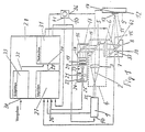
- Fig. 1 is a schematic diagram of a device shows to carry out the procedure, the of a beam source 1, e.g. a solid-state laser Power beam 2 of a laser beam shaping hardening optics 4 is supplied in which it is from a lens 3 to a partially transparent Deflecting mirror 5 deflected and after deflection 90 ° through the latter via a further lens 6 onto one controllable in terms of its deflection speed (arrow 7) Vibration mirror 8 is directed.
- a beam source 1 e.g. a solid-state laser Power beam 2 of a laser beam shaping hardening optics 4
- a beam source e.g. a solid-state laser Power beam 2 of a laser beam shaping hardening optics 4
- a beam source 1 e.g. a solid-state laser Power beam 2 of a laser beam shaping hardening optics 4
- a beam source 1 e.g. a solid-state laser Power beam 2 of a laser beam shaping hardening optics 4
- the power beam 2 is on the surface 9 one movable by a drive motor 10 (see double arrow 11) Workpiece 12 in such a way to harden the latter focused a beam spot that the impact 14 of the Working laser beam spot 13 during curing by the Deflection movement of the oscillating mirror 8 transversely to the feed direction 11 of the workpiece 12 oscillates.
- the lens 20 and the pinhole 21 are, as can be seen from the double arrows 23 and 24 is in the beam direction or perpendicular to it back and forth.
- the IR detector 22 is always exactly the temperature at each point of impact 14 of the working laser beam spot measured immediately.
- the input 26 of the control circuit 27 of the controller 28 is still with the output 35 of the beam source 1, the output 36 of the drive motor generating the feed movement 10 and the output 37 of a drive 38 in terms of its Deflection speed controllable deflection mirror 8 for recording the actual beam power or the actual feed movement or the actual beam deflection.
- the input 34 of the control loop processing setpoints 33 of the controller 28 are used as processing-specific specifications, from which the required temperatures or required Have the energy supply determined, e.g. Material properties, the hardening depth, the heating and cooling time, the Workpiece geometry, the deflection movement, the feed movement and entered the processing time.
- the output 39 of the control loop of the controller 28, in which the actual values and target values entered via input 30 After their comparison, the required manipulated variables are generated be with the input 40 of the beam source 1, the Input 41 of the drive motor 10 and input 42 of the drive 38 of the oscillating mirror 8 for controlling the laser beam energy or the feed movement or the beam deflection connected.
- Temperatures caused by changes in component geometry and the resulting volume and / or material distribution are caused by means of the controller's computer 28 the component location - and shape calculated Identification of the characteristic component geometry special treatment algorithms required for each Treatment situation targeted by the controller 28 used.
- the special treatment algorithms targeted for throttling the energy supply at critical parts of the component such as edges, Tips, holes and the like used.
- the controller 28 analyzes the temperature measurement data determined continuously whether the proportionality of the deviation of the controlled variable (Temperature) and the manipulated variables (laser power; Deflection movement of the deflection mirror; Feed movement) maintained is. If a temperature value (controlled variable) is below of a set threshold, although the laser power (manipulated variable) increases, so when used the processing / measuring range of the system immediately of the controller in different subsystems / areas divided, for which on the one hand the proportionality of the Deviation from controlled variable and manipulated variable as previously applies and in which, on the other hand, at a high deflection speed only enter a relatively small amount of energy becomes.
- the further similar schematic representations of workpiece 12 with associated laser beam guidance 2 or beam spot 13 show a method according to the method adapted edge treatment for double-sided radiation detect an edge of the workpiece 12.
- the angle of incidence ⁇ of the laser beam based on the Edge sides can be variable.
- the distance can also the hardness optics 4 can be changed to the workpiece 12 (FIG. 8) or be constant (Fig. 10).
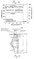
- FIG. 11 shows a side view of the workpiece 12 with an associated one Laser beam 2, which is perpendicular to the workpiece surface hits, the angle of incidence ⁇ also varies can be.
- Fig. 11 was a temperature course over the track width determined how this can be seen in the diagram of FIG. 12 is where the beam position is plotted against temperature is. 120 measurements are shown Measuring frequency of 60 Hz corresponds to a process duration of 2s. The position of the edge is at beam position 13, as can be seen from Fig. 12.
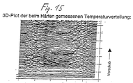
- FIG. 13 shows a schematic sectional view of one exposed to oxide-free curing workpiece 12 with a Blind hole and eight over the circumference of the workpiece in the Distance from each other arranged threaded holes in a Direction of the working laser beam according to arrow 45.
- the diagram associated with FIG. 13 of FIG. 14 is the laser power in W, the relative temperature in mV and the processing time plotted in s, the circumference of the workpiece hardened over 360 ° at a feed rate of 0.1 m / min has been.
Landscapes
- Physics & Mathematics (AREA)
- Optics & Photonics (AREA)
- Engineering & Computer Science (AREA)
- Plasma & Fusion (AREA)
- Mechanical Engineering (AREA)
- Laser Beam Processing (AREA)
Claims (7)
- Procédé pour la reconnaissance et le suivi de la géométrie au moyen d'une mesure de température analysée localement lors du traitement thermique d'un composant (12) au moyen de rayonnement laser (2), en particulier lors du durcissement de conversion par rayonnement laser (2), la zone de température du composant (12) étant enregistrée par un procédé sans contact au moyen d'un système capteur photothermique,
caractérisé en ce que
l'enregistrement de la zone de température générée dans le composant (12) par la chaleur de procédé s'effectue dans sa projection bidimensionnelle, la position et la forme du composant sont calculées à partir des données calculées de la zone de température sur la base de variations de la conduction thermique locale causée par des modifications de la géométrie du composant et de la répartition du volume et/ou du matériau ainsi conditionnée et, après l'identification de la géométrie caractéristique du composant, des algorithmes spéciaux de traitement sont utilisés de façon adéquate pour les situations de traitement nécessaires respectives. - Procédé selon la revendication 1, caractérisé en ce que les algorithmes spéciaux de traitement sont utilisés de façon adéquate pour l'étranglement de l'arrivée d'énergie dans des endroits critiques du composant (12) tels que des arêtes, des extrémités, des alésages et similaires.
- Procédé selon les revendications 1 et 2, caractérisé en ce que l'identification d'une arête de composant et sa position par rapport au système de traitement est utilisée pour la commande d'un acteur de telle sorte que la position de la zone de traitement est corrigée par une comparaison prévue - réelle et qu'ainsi un réglage de la position est possible sur la base d'un capteur photothermique.
- Procédé selon la revendication 3, caractérisé en ce qu'on utilise comme acteur une commande contrôlée de miroir pivotant (38).
- Procédé selon les revendications 1 à 4, caractérisé en ce qu'une répartition homogène de la température dans le composant (12) est générée par une arrivée d'énergie analysée localement et la répartition du matériau dans le composant (12) et donc sa forme sont calculée à partir de la répartition dans l'espace de l'arrivée d'énergie, les erreurs de réglage, résiduelles en raison du principe, du signal de température étant utilisées comme informations supplémentaires pour la détermination de la position et de la forme du composant.
- Procédé selon la revendication 1, caractérisé en ce que les algorithmes de traitement, spéciaux et correspondant à l'identification de la géométrie du composant, sont utilisés pour le guidage de trajectoire (44) d'un robot.
- Procédé pour le durcissement de surfaces de pièce (9) au moyen de faisceaux (2), en particulier au moyen de faisceaux laser (2), avec lequel une optique de trempe (4) formant le faisceau laser et la surface de la pièce (9) sont déplacées l'une par rapport à l'autre, le lieu d'impact (14) de la tâche du faisceau laser de travail (13) oscille pendant le durcissement par des mouvements de déviation d'appareils de conversion de faisceau de l'optique de dureté (4) transversalement au sens d'avancement (11), le rayonnement de température (15) du lieu d'impact (14), oscillant transversalement au sens d'avancement (11), de la tâche du faisceau laser de travail (13) est amené au moyen de miroirs (5) semi-argentés de façon colinéaire par rapport à la trajectoire des rayons (2) du laser de travail (1) à travers l'optique de dureté (4) à un dispositif de contrôle de température (17), par lequel on enregistre toujours momentanément la température au lieu d'impact (14) de la tâche du faisceau laser de travail (13), les données calculées de mesure de température sont entrées dans un régulateur (28) couplé avec la source de rayonnement (1), la déviation du faisceau et le mouvement d'avancement, régulateur dans lequel une répartition de la température est calculée transversalement au sens d'avancement (11) et par lequel une répartition ajustée de l'énergie du faisceau laser et une commande adaptée du mouvement de déviation des dispositifs de conversion de faisceau de l'optique de dureté (4) et du mouvement d'avancement s'effectuent en tenant compte de données spécifiques au traitement,
caractérisé en ce que
les données calculées de la mesure de température sont analysées en permanence pour savoir si la proportionnalité de l'écart de la grandeur de réglage (température) et des grandeurs de commande (puissance de laser ; mouvement de déviation des dispositifs de conversion de faisceau ; mouvement d'avancement) est respectée, et dans le cas où une valeur de température est calculée au-dessous d'une valeur seuil définie, bien que la puissance du laser ait été augmentée, ce qui apparaít en particulier sur les arêtes, la plage de traitement/mesure est divisée automatiquement en systèmes partiels/secteur différents, pour lesquels d'une part la proportionnalité de l'écart de la grandeur de réglage et des grandeurs de commande est toujours valable et dans lesquels d'autre part, même avec une vitesse de déviation élevée, seule une quantité d'énergie relativement faible est apportée.
Priority Applications (2)
| Application Number | Priority Date | Filing Date | Title |
|---|---|---|---|
| EP19970116420 EP0904886B1 (fr) | 1997-09-20 | 1997-09-20 | Procédé de reconnnaissance de géométrie et de suivi au cours de traitement thermique d'éléments au moyen de faisceau laser |
| DE59710231T DE59710231D1 (de) | 1997-09-20 | 1997-09-20 | Verfahren zur Geometrieerkennung und -verfolgung bei der thermischen Bearbeitung von Bauteilen mittels Laserstrahlung |
Applications Claiming Priority (1)
| Application Number | Priority Date | Filing Date | Title |
|---|---|---|---|
| EP19970116420 EP0904886B1 (fr) | 1997-09-20 | 1997-09-20 | Procédé de reconnnaissance de géométrie et de suivi au cours de traitement thermique d'éléments au moyen de faisceau laser |
Publications (2)
| Publication Number | Publication Date |
|---|---|
| EP0904886A1 EP0904886A1 (fr) | 1999-03-31 |
| EP0904886B1 true EP0904886B1 (fr) | 2003-06-04 |
Family
ID=8227382
Family Applications (1)
| Application Number | Title | Priority Date | Filing Date |
|---|---|---|---|
| EP19970116420 Expired - Lifetime EP0904886B1 (fr) | 1997-09-20 | 1997-09-20 | Procédé de reconnnaissance de géométrie et de suivi au cours de traitement thermique d'éléments au moyen de faisceau laser |
Country Status (2)
| Country | Link |
|---|---|
| EP (1) | EP0904886B1 (fr) |
| DE (1) | DE59710231D1 (fr) |
Cited By (1)
| Publication number | Priority date | Publication date | Assignee | Title |
|---|---|---|---|---|
| US12191536B2 (en) | 2019-02-25 | 2025-01-07 | Audi Ag | Method for producing a bipolar plate strand, method for producing a bipolar plate and device for carrying out the method |
Families Citing this family (6)
| Publication number | Priority date | Publication date | Assignee | Title |
|---|---|---|---|---|
| DE102004051876A1 (de) * | 2004-10-20 | 2006-04-27 | Fraunhofer-Gesellschaft zur Förderung der angewandten Forschung e.V. | Anordnung und Verfahren zur ortsaufgelösten Temperaturmessung bei einem Laserbearbeitungsverfahren |
| DE102009005935B4 (de) | 2009-01-23 | 2010-10-07 | Danfoss Compressors Gmbh | Verfahren zum Kalibrieren einer Pleuelstangenanordnung und Pleuelstangenanordnung |
| DE102010010148A1 (de) | 2010-03-04 | 2010-10-14 | Daimler Ag | Verfahren zum Beschichten von Lagerwerkstoffen |
| CN111551071A (zh) * | 2020-04-30 | 2020-08-18 | 西安工业大学 | 一种微火工品爆轰温度场测试装置及三维重构方法 |
| CN113686241B (zh) * | 2021-08-06 | 2022-06-14 | 大连理工大学 | 一种高温表面线激光几何测量误差分析方法 |
| CN119511056B (zh) * | 2024-10-18 | 2025-08-05 | 武汉铱科赛科技有限公司 | 一种盲孔可靠性测试方法、设备、装置及系统 |
Family Cites Families (2)
| Publication number | Priority date | Publication date | Assignee | Title |
|---|---|---|---|---|
| JPS62136039A (ja) * | 1985-12-09 | 1987-06-19 | Rohm Co Ltd | 半導体チツプの不良マ−キング方法 |
| GB2196155B (en) * | 1986-09-20 | 1991-02-20 | Mitsubishi Electric Corp | Control apparatus for energy beam hardening |
-
1997
- 1997-09-20 DE DE59710231T patent/DE59710231D1/de not_active Expired - Lifetime
- 1997-09-20 EP EP19970116420 patent/EP0904886B1/fr not_active Expired - Lifetime
Cited By (1)
| Publication number | Priority date | Publication date | Assignee | Title |
|---|---|---|---|---|
| US12191536B2 (en) | 2019-02-25 | 2025-01-07 | Audi Ag | Method for producing a bipolar plate strand, method for producing a bipolar plate and device for carrying out the method |
Also Published As
| Publication number | Publication date |
|---|---|
| EP0904886A1 (fr) | 1999-03-31 |
| DE59710231D1 (de) | 2003-07-10 |
Similar Documents
| Publication | Publication Date | Title |
|---|---|---|
| EP0707920B1 (fr) | Tête d'usinage au laser compacte pour l'usinage de matériaux au laser, avec une commande de guidage en ligne intégrée | |
| EP2544849B1 (fr) | Tête de travail au laser et procédé de travail au laser | |
| EP2691206B1 (fr) | Procédé d'usinage par faisceau laser d'une pièce | |
| EP0060980A1 (fr) | Dispositif de coupage par rayons de laser | |
| DE4206584C2 (de) | Vorrichtung und Verfahren zum Verbinden zweier Bauteile mittels Ultraschall | |
| EP0700325A1 (fr) | Procede permettant de travailler des materiaux par rayonnement emis par des diodes | |
| DE29505985U1 (de) | Vorrichtung zum Bearbeiten, insbesondere zum Polieren und Strukturieren von beliebigen 3D-Formflächen mittels eines Laserstrahls | |
| EP1424613A1 (fr) | Procédé et dispositif d'usinage d'une pièce | |
| EP1640101A2 (fr) | Méthode et appareil pour contrôler un procédé d'usinage automatique. | |
| DE3212589A1 (de) | Laserstrahl-bearbeitungsmaschine und verfahren zur laserstrahl-bearbeitung von werkstuecken | |
| EP2027962A1 (fr) | Appareil et procédé de soudure destinés à la soudure orbitale de tuyaux | |
| DE4014251A1 (de) | Verfahren und system zur raupenherstellungsguetekontrolle | |
| DE19615069A1 (de) | Verfahren und Vorrichtung zum Nachführen von Werkzeugen mittels Kantenverfolgung | |
| DE4316829A1 (de) | Verfahren zur Materialbearbeitung mit Diodenstrahlung | |
| EP0187934A2 (fr) | Dispositif pour traiter des pièces au moyen d'un rayon laser sortant d'une tête de laser | |
| DE102014101568A1 (de) | Verfahren und Vorrichtung zum Laserschweißen oder -schneiden mit einem dynamisch anpassbaren Analysebereich | |
| EP0904886B1 (fr) | Procédé de reconnnaissance de géométrie et de suivi au cours de traitement thermique d'éléments au moyen de faisceau laser | |
| DE19853733C1 (de) | Verfahren zur lokal gezielten Wärmebehandlung von Werkstückoberflächen | |
| EP2091699B1 (fr) | Procédé et dispositif pour le positionnement fin d'un outil avec un organe de manipulation | |
| DE112021003769T5 (de) | Laserbearbeitungssystem | |
| EP0309973A1 (fr) | Procédé de traitement thermique de pièces en phase solide par un faisceau laser | |
| EP0822027B2 (fr) | Procédé de durcissement de la surface d'une pièce à travailler au moyen d'un faisceau, en particulier un faisceau laser et dispositif de réalisation de ce procédé | |
| DE102008013398A1 (de) | Verfahren zur Programmierung und Steuerung einer Remote-Bearbeitungsanlage | |
| EP4126434B1 (fr) | Procédé de détermination des paramètres de soudage pour un procédé de soudage sur une pièce et dispositif de soudage permettant de mettre en uvre un procédé de soudage sur une pièce à l'aide des paramètres de soudage définis | |
| WO2000076715A2 (fr) | Dispositif de determination de la position de domaines d'emission d'un processus thermique avec apport d'energie localement limite |
Legal Events
| Date | Code | Title | Description |
|---|---|---|---|
| PUAI | Public reference made under article 153(3) epc to a published international application that has entered the european phase |
Free format text: ORIGINAL CODE: 0009012 |
|
| AK | Designated contracting states |
Kind code of ref document: A1 Designated state(s): CH DE FR GB IT LI NL SE |
|
| 17P | Request for examination filed |
Effective date: 19990927 |
|
| AKX | Designation fees paid |
Free format text: CH DE FR GB IT LI NL SE |
|
| 17Q | First examination report despatched |
Effective date: 20011024 |
|
| GRAH | Despatch of communication of intention to grant a patent |
Free format text: ORIGINAL CODE: EPIDOS IGRA |
|
| GRAH | Despatch of communication of intention to grant a patent |
Free format text: ORIGINAL CODE: EPIDOS IGRA |
|
| GRAA | (expected) grant |
Free format text: ORIGINAL CODE: 0009210 |
|
| AK | Designated contracting states |
Designated state(s): CH DE FR GB IT LI NL SE |
|
| PG25 | Lapsed in a contracting state [announced via postgrant information from national office to epo] |
Ref country code: NL Free format text: LAPSE BECAUSE OF FAILURE TO SUBMIT A TRANSLATION OF THE DESCRIPTION OR TO PAY THE FEE WITHIN THE PRESCRIBED TIME-LIMIT Effective date: 20030604 Ref country code: IT Free format text: LAPSE BECAUSE OF FAILURE TO SUBMIT A TRANSLATION OF THE DESCRIPTION OR TO PAY THE FEE WITHIN THE PRESCRIBED TIME-LIMIT;WARNING: LAPSES OF ITALIAN PATENTS WITH EFFECTIVE DATE BEFORE 2007 MAY HAVE OCCURRED AT ANY TIME BEFORE 2007. THE CORRECT EFFECTIVE DATE MAY BE DIFFERENT FROM THE ONE RECORDED. Effective date: 20030604 Ref country code: GB Free format text: LAPSE BECAUSE OF FAILURE TO SUBMIT A TRANSLATION OF THE DESCRIPTION OR TO PAY THE FEE WITHIN THE PRESCRIBED TIME-LIMIT Effective date: 20030604 Ref country code: FR Free format text: LAPSE BECAUSE OF FAILURE TO SUBMIT A TRANSLATION OF THE DESCRIPTION OR TO PAY THE FEE WITHIN THE PRESCRIBED TIME-LIMIT Effective date: 20030604 |
|
| REG | Reference to a national code |
Ref country code: GB Ref legal event code: FG4D Free format text: NOT ENGLISH |
|
| REG | Reference to a national code |
Ref country code: CH Ref legal event code: EP |
|
| REF | Corresponds to: |
Ref document number: 59710231 Country of ref document: DE Date of ref document: 20030710 Kind code of ref document: P |
|
| PG25 | Lapsed in a contracting state [announced via postgrant information from national office to epo] |
Ref country code: SE Free format text: LAPSE BECAUSE OF FAILURE TO SUBMIT A TRANSLATION OF THE DESCRIPTION OR TO PAY THE FEE WITHIN THE PRESCRIBED TIME-LIMIT Effective date: 20030904 |
|
| PG25 | Lapsed in a contracting state [announced via postgrant information from national office to epo] |
Ref country code: LI Free format text: LAPSE BECAUSE OF NON-PAYMENT OF DUE FEES Effective date: 20030930 Ref country code: CH Free format text: LAPSE BECAUSE OF NON-PAYMENT OF DUE FEES Effective date: 20030930 |
|
| NLV1 | Nl: lapsed or annulled due to failure to fulfill the requirements of art. 29p and 29m of the patents act | ||
| GBV | Gb: ep patent (uk) treated as always having been void in accordance with gb section 77(7)/1977 [no translation filed] |
Effective date: 20030604 |
|
| PLBE | No opposition filed within time limit |
Free format text: ORIGINAL CODE: 0009261 |
|
| STAA | Information on the status of an ep patent application or granted ep patent |
Free format text: STATUS: NO OPPOSITION FILED WITHIN TIME LIMIT |
|
| REG | Reference to a national code |
Ref country code: CH Ref legal event code: PL |
|
| 26N | No opposition filed |
Effective date: 20040305 |
|
| EN | Fr: translation not filed | ||
| PGFP | Annual fee paid to national office [announced via postgrant information from national office to epo] |
Ref country code: DE Payment date: 20130322 Year of fee payment: 16 |
|
| REG | Reference to a national code |
Ref country code: DE Ref legal event code: R119 Ref document number: 59710231 Country of ref document: DE Effective date: 20140401 |
|
| PG25 | Lapsed in a contracting state [announced via postgrant information from national office to epo] |
Ref country code: DE Free format text: LAPSE BECAUSE OF NON-PAYMENT OF DUE FEES Effective date: 20140401 |