EP0905096A2 - Verfahren und Vorrichtung zur Herstellung von Flaschen und Vorrichtung zur Bekleidung von Flaschen - Google Patents
Verfahren und Vorrichtung zur Herstellung von Flaschen und Vorrichtung zur Bekleidung von Flaschen Download PDFInfo
- Publication number
- EP0905096A2 EP0905096A2 EP98117994A EP98117994A EP0905096A2 EP 0905096 A2 EP0905096 A2 EP 0905096A2 EP 98117994 A EP98117994 A EP 98117994A EP 98117994 A EP98117994 A EP 98117994A EP 0905096 A2 EP0905096 A2 EP 0905096A2
- Authority
- EP
- European Patent Office
- Prior art keywords
- bottle
- chamber
- blowing
- coating
- suction
- Prior art date
- Legal status (The legal status is an assumption and is not a legal conclusion. Google has not performed a legal analysis and makes no representation as to the accuracy of the status listed.)
- Granted
Links
Images




Classifications
-
- C—CHEMISTRY; METALLURGY
- C03—GLASS; MINERAL OR SLAG WOOL
- C03B—MANUFACTURE, SHAPING, OR SUPPLEMENTARY PROCESSES
- C03B29/00—Reheating glass products for softening or fusing their surfaces; Fire-polishing; Fusing of margins
- C03B29/04—Reheating glass products for softening or fusing their surfaces; Fire-polishing; Fusing of margins in a continuous way
- C03B29/06—Reheating glass products for softening or fusing their surfaces; Fire-polishing; Fusing of margins in a continuous way with horizontal displacement of the products
-
- C—CHEMISTRY; METALLURGY
- C03—GLASS; MINERAL OR SLAG WOOL
- C03C—CHEMICAL COMPOSITION OF GLASSES, GLAZES OR VITREOUS ENAMELS; SURFACE TREATMENT OF GLASS; SURFACE TREATMENT OF FIBRES OR FILAMENTS MADE FROM GLASS, MINERALS OR SLAGS; JOINING GLASS TO GLASS OR OTHER MATERIALS
- C03C17/00—Surface treatment of glass, not in the form of fibres or filaments, by coating
- C03C17/001—General methods for coating; Devices therefor
- C03C17/003—General methods for coating; Devices therefor for hollow ware, e.g. containers
- C03C17/005—Coating the outside
-
- Y—GENERAL TAGGING OF NEW TECHNOLOGICAL DEVELOPMENTS; GENERAL TAGGING OF CROSS-SECTIONAL TECHNOLOGIES SPANNING OVER SEVERAL SECTIONS OF THE IPC; TECHNICAL SUBJECTS COVERED BY FORMER USPC CROSS-REFERENCE ART COLLECTIONS [XRACs] AND DIGESTS
- Y02—TECHNOLOGIES OR APPLICATIONS FOR MITIGATION OR ADAPTATION AGAINST CLIMATE CHANGE
- Y02P—CLIMATE CHANGE MITIGATION TECHNOLOGIES IN THE PRODUCTION OR PROCESSING OF GOODS
- Y02P40/00—Technologies relating to the processing of minerals
- Y02P40/50—Glass production, e.g. reusing waste heat during processing or shaping
- Y02P40/57—Improving the yield, e-g- reduction of reject rates
Definitions
- the present invention relates to a bottle making method capable of uniformizing temperature distribution on the outer surface of a bottle during transportation of the bottle delivered from a bottle making machine to a hearth so that a coating process can satisfactorily be achieved, an apparatus for carrying out the bottle making method, and a bottle coating apparatus.
- a glass bottle formed by a bottle making machine by blow molding in a bottle-shape having a neck, a shoulder, a body and a bottom maintains a surface temperature of 500°C or above on a conveyor for conveying the glass bottle to a lehr.
- An oxide coating such as a coating of SnO 2 , TiO 2 or the like, can be formed over the outer surface of the bottle by placing a tunnel-shaped hood over the conveyor conveying the bottle to the lehr, and filling the interior of the hood with a substance capable of making hydrolysis or oxidation at temperatures of 500°C or above to produce an oxide, such as SnCl 4 , an organic tin compound, TiCl 4 , titanium alkoxide or the like.
- the oxide coating the outer surface of the bottle can prevent the development of microcracks, which is a principal cause of reduction in the strength of glass, and therefore the thickness of the glass necessary for securing the strength can be reduced.
- a process of coating the outer surface of a glass bottle with such an oxide coating is called a hot-end coating process which contributes to producing lightweight glass bottles.
- Glass bottles are classified into two groups, i.e., a group of one-way bottles which are not supposed to be recovered and reused, and a group of returnable bottles which are supposed to be recovered and refilled for reuse, such as beer bottles, sake bottles and the like.
- Returnable bottles are cleaned by a hot-alkali cleaning process before reuse.
- the hot-end coating process has not been applied to making returnable bottles because a coating formed on the outer surface of a bottle by the hot-end coating process comes off when the bottle is subjected to the hot-alkali cleaning process.
- 3-131547 discloses a technique capable of forming a coating which withstands hot-alkali cleaning by keeping the surface of a glass bottle at temperatures in the range of 550°C to 700°C during a coating process and controlling process conditions so that a coating of a thickness in the range of 400 to 1000 ⁇ .
- a bottle transporting method proposed in JP-A No. 6-157062 fixes time between the delivery of a molded glass bottle on a conveyor and the entrance of the same into a lehr regardless of the type of a mold employed to achieve appropriate temperature control.
- This previously proposed bottle transporting method is capable of removing the surface temperature difference between glass bottles during coating formation attributable to the difference between the types of molds used for molding the glass bottles.
- different parts in a glass bottle have different temperatures, respectively, and some parts of a glass bottle do not meet the temperature condition specified in JP-A No. 3-131547.
- a glass bottle has a locally thick part of an excessively high temperature, it is possible that part of the coating formed on the locally thick part comes off when the glass bottle is subjected to the hot-alkali cleaning process even if the foregoing temperature condition is satisfied.
- a bottle making method for making a bottle having a neck, a shoulder, a body and a bottom have a uniform surface temperature distribution comprises: the steps of cooling a part of the body of the bottle formed during blow molding of the bottle which has a thickness greater than that of other parts of the body immediately after the bottle has been formed; and heating the other parts of the body, the neck, the shoulder and the bottom.
- a bottle making apparatus for making a bottle having a neck, a shoulder, a body and a bottom comprises: a cooling means for cooling a part of the body of the bottle formed during blow molding of the bottle which has a thickness greater than that of other parts of the body immediately after the bottle has been formed; and a heating means for heating the other parts of the body, the neck, the shoulder and the bottom.
- a bottle coating apparatus comprises a bottle coating chamber; a blowing chamber disposed near the bottle processing chamber; a suction chamber disposed near the bottle processing chamber; and a circulation blower disposed between the blowing chamber and the suction chamber to circulate a process gas sequentially through the blowing chamber, the bottle coating chamber and the suction chamber; wherein the blowing chamber is provided with a blowing opening opening into the bottle coating chamber, the chamber is provided with a suction opening opening into the bottle coating chamber, the blowing opening of the blowing chamber is on a level below a level corresponding to the center of gravity of the bottle.
- the bottle 1 has a neck 1a of a great wall thickness, a shoulder 1b of a wall thickness which becomes smaller downward, a cylindrical body 1c continuous with the shoulder 1b, and a bottom 1d.
- the neck 1a is formed first when making the bottle 1 by blow molding. Therefore, the neck 1a and the shoulder 1b cool more than the body 1c and the temperatures of the neck 1a and the shoulder 1b are lower than that of the body 1c when the bottle 1 is formed completely.
- a longitudinally elongate bottle such as a beer bottle, is made by two-stage blow molding.
- the bottle 1 is a longitudinally elongate one, it often occurs that a settle line 1e having a great thickness is formed in a middle part of the body 1c, and the temperature of the settle line 1e remains higher than those of other parts of the bottle 1.
- a bottle making apparatus 2 in a first embodiment heats and cools parts of the bottle 1 according to a temperature distribution on the bottle 1.
- FIGs. 1 and 2 showing the bottle making apparatus 2 has hollow, gantrylike frames 3 fixedly installed at a predetermined interval of, for example, about 800 mm with respect to a direction in which the bottle 1 is conveyed so as to straddle a bottle conveying path.
- Each of the frames 3 has opposite inner walls having parallel lower parts defining a space conforming to a lower part of the external shape of the bottle 1, and upper parts inclined toward each other so as to define an upward tapered space conforming to an upper part of the external shape of the bottle 1.
- the bottle 1 is conveyed by a conveyor 4 through the space defined by the gantrylike frames 3.
- Burner pipes 5 are extended horizontally on levels corresponding to the neck 1a, the shoulder 1b and a lower part of the body 1c of the bottle 1, respectively.
- Cooling pipes 6 are extended on a level corresponding to the settle line 1e.
- Each burner pipe 5 is provided with, for example, 10 burners 7 arranged at equal intervals and opening toward the bottle 1 conveyed through the gantrylike frames 3, and each cooling pipe 6 is provided with, for example, 10 air blowing openings 8.
- Combustion air a 1 is supplied through an air pipe 9 and the gantrylike frames 3 to the burner pipes 5.
- a fuel gas b such as LPG
- the burners 7 blow flames c against the bottle 1.
- Cooling air a is blown through the air blowing openings 8 toward the settle line 1e of the bottle 1.
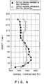
- Heat generating rate at which the burners 7 attached to the burner pipes 5 generate heat and air blowing rate at which the cooling air a is blown through the air blowing opening of the cooling pipe 6 are controlled so that the bottle 1 has a uniform surface temperature distribution. Particularly, even if the settle line 1e is formed by blow-and-blow molding, the settle line 1e can surely be cooled to reduce the irregularity of the surface temperature distribution of the bottle 1.
- the bottle making apparatus 2 of the present invention was installed so as to straddle the conveyor 4 as shown in Fig. 3.
- the conveyor 4 conveyed glass bottles of 475 g in weight, 289 mm in height and 74 mm in maximum outside diameter at intervals of 133 mm at a velocity of 11.4 m/min.
- the top burner pipes 5 were disposed at a height A of 220 mm
- the middle burner pipes 5 were disposed at a height B of 170 mm
- the bottom burner pipes 5 were disposed at a height C of 10 mm
- respective positions of the burners 7 of the top, the middle and the bottom burner pipes 5 were adjusted so as to blow flames c to the neck 1a, the shoulder 1b and the bottom 1d of each bottle 1, respectively.
- the fuel gas b was burnt by the burners 7 of the top, the middle and the bottom burner pipes 5 at heat generating rates of 30,000 kcal/hr, 23,000 kcal/hr and 20,000 kcal/hr, respectively.
- the cooling pipes 6 were disposed at a height D of 80 mm, and 0.7 kg/cm 2 compressed air a was blown against a part of each bottle 1 around the settle line 1e for cooling.
- the bottle processed by the bottle making apparatus 2 for surface temperature distribution control and the bottle not processed by the bottle making apparatus 2 were coated with a 800 ⁇ thick SnO 2 coating.
- the surfaces of the bottles coated with the SnO 2 coating were examined after immersing the bottles in a 4% NaOH solution of 80°C for six hours.
- the bottle processed by the bottle making apparatus 2 of the present invention assumed a whitish appearance and the SnO 2 coating did not come off at all.
- the present invention employs the cooling means corresponding to a part having an increased wall thickness of the glass bottle formed just now having the neck, the shoulder, the body and the bottom, and the heating means corresponding to the body excluding the part having an increased wall thickness, the neck and the shoulder of the glass bottle.
- the surface temperature distribution on the entire glass bottle is uniform, and therefore the local exfoliation of a coating formed over the outer surface of the glass bottle in the following process does not occur at all.
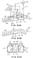
- Fig. 6(A) is a schematic perspective view of a bottle coating apparatus 111 in a second embodiment according to the present invention
- Fig. 6(B) is a perspective view of blowing openings and suction openings formed in the bottle coating apparatus 111 of Fig. 6(A)
- Fig. 6(C) is a sectional view of assistance in explaining currents produced by a circulation blower.
- the bottle coating apparatus 111 has a chamber block 111a fixedly installed so as to straddle the conveyor 104, and a large circulation blower 112.
- the chamber block 111a has a longitudinal channel through which bottles 102 are conveyed by the conveyor 104.
- the chamber block 111a has four connecting openings (middle openings) connected to the large circulation blower 112, and a front and a back connecting opening connected to an exhaust blower 120.
- the chamber block 111a has a bottle coating chamber 111d through which the bottles 102 are conveyed, blowing chambers 111b, and suction chambers 111c. Process gas inlets 113 are formed in lower parts of side walls of the blowing chambers 111b.
- the blowing chambers 111b and the suction chambers 111c of the chamber block 111a adjoin the bottle coating chamber 111d, and each blowing chamber 111b and the suction chamber 111c corresponding to the blowing chamber 111b are disposed opposite to each other on the opposite sides of the bottle coating chamber 111d, respectively.
- Fig. 6(B) shows the bottle coating apparatus 111 of Fig. 6(A), in which the chamber block 111, excluding partition walls separating the blowing chambers 111b and the suction chambers 111c of the chamber block 111a from the bottle coating chamber 111d, is removed.
- the blowing chamber 111b is provided with an air blowing opening 114 through which air blown by the circulation blower 112 is blown into the bottle chamber 111d.
- the suction chamber 111c is provided with a suction opening 115 through which air is sucked from the bottle chamber 111c.
- Fig 6(C) is a sectional view taken on line A-A in Fig. 6(B).
- air blown by the circulation blower 112 flows as indicated by the downward arrows, and mixes with a process gas supplied through the process gas inlets 113 in the blowing chambers 111b to produce a mixed gas.
- the mixed gas flows from the blowing chambers 111b to the bottle coating chamber 111d through the air blowing openings 114 and then flows into a space surrounding the glass bottles 102 being conveyed by the conveyor 104 to form a coating on the outer surfaces of the glass bottles 102.
- the process gas is a gas of a substance capable of making hydrolysis or oxidation at temperatures in the temperature range suitable for oxide film formation to produce an oxide, such as SnCl 4 , an organic tin compound, TiCl 4 , titanium alkoxide or the like.
- the process gas fills up the bottle coating chamber 111d and forms an oxide coating, such as a SnO 2 coating or a TiO 2 coating, on the surfaces of the bottles 102.
- the oxide coating formed on the surfaces of the bottles 102 prevents the development of microcracks, which is a principal cause of reduction in the strength of glass, and hence the thickness of the wall of the glass bottle necessary for securing sufficient strength can be reduced.
- Fig. 7(A) is a schematic perspective view of a bottle coating apparatus 111 in anohter embodiment according to the present invention
- Fig. 7(B) is a perspective view of blowing openings and suction openings formed in the bottle coating apparatus 111 of Fig. 7(A)
- Fig. 7(C) is a sectional view taken on line B-B in Fig. 7(B) of assistance in explaining currents produced by a circulation blower.
- the bottle coating apparatus in the embodiment shown in Figs. 7(A) ⁇ 7(C) is similar in construction to the bottle coating apparatus in the second embodiment shown in Figs. 6(A) ⁇ 6(C), excepting that the bottle coating apparatus in Figs.
- FIG. 7(A) - 7(C) has chamber sets each consisting of a blowing chamber 111b and a suction chamber 111c so that the blowing chamber 111b underlies the suction chamber 111c, and the blowing chamber 111b and the suction chamber 111c are separated by a partition wall 111e, and the chamber sets are disposed opposite to each other on the opposite sides of a bottle coating chamber 111d, respectively.
- air blown by a circulation blower 112 flows as indicated by the downward arrows, mixes with a process gas supplied through process gas inlets 113 in the blowing chambers 111b to produce a mixed gas.
- the mixed gas flows from the blowing chambers 111b to the bottle coating chamber 111d through air blowing openings 114 and then flows into a space surrounding glass bottles 102 being conveyed by a conveyor 104 to form a coating on the outer surfaces of the glass bottles 102. Then, the used mixed gas is sucked through suction openings 115 into the suction chambers 111c and flows as indicated by the upward arrows to the circulation blower 112. Thus, the air blown by the circulation blower 112 circulates through the bottle coating apparatus.
- Figs. 6(A) ⁇ 6(C) and Figs. 7(A) ⁇ 7(C) if the bottle 102 is subjected to temperature control immediately before the bottle 102 reaches the entrance of the bottle coating apparatus, the surface temperature of the bottle 102 will be higher than that of the bottle 102 which is subject to a hot-end coating process. Accordingly, very rapid rising air currents flow along the outer surface of the bottle 102. The velocity of such rising air currents is high enough to form an alkali-proof coating, and hence a highly alkali-proof coating can be formed by supplying a process gas together with the rising air currents.
- the blowing openings 114 are formed on a level below that of the center G of gravity of the bottle 102 so that the bottle 102 may not be caused to tumble over by air blown through the blowing openings 114.
- the area of the blowing opening 114 is determined so as to correspond to the blowing capacity of the circulation blower 112 so that a uniform, highly alkali-proof coating may be formed.
- the correspondence of the area of the blowing openings 114 to the blowing capacity of the circulation blower 112 is dependent on the weight, height, outside diameter of the bottle 102 and processing rate at which the bottle coating apparatus processes bottles.
- the area of the blowing openings 114 is quite different from that for ordinary hot-end coating.
- the sum of the areas of the blowing openings 114 is in the range of 3000 to 30,000 mm 2 , which is in the range of 1/5 to 1/2 of the sum of the areas of blowing openings in an ordinary coating apparatus.
- the blowing capacity of the circulation blower 112 is in the range of 5 to 20 m 3 /min, which is about twenty times the blowing capacity of a circulation blower employed in an ordinary coating apparatus.
- the suction openings 115 of the bottle coating apparatuses shown in Figs. 6(B) and 7(B) have the shape of a horizontally elongate rectangle, and the area of the suction openings 115 is in the range of three to twenty times that of the blowing openings 114.
- Bottles 102 were coated with an oxide coating by the bottle coating apparatus shown in Figs. 6(A) to 6(C).
- the surface temperature of the bottles 102 was adjusted to temperatures of 620 ⁇ 20°C while the bottles 102 arranged at intervals of 133 mm on the conveyor 104 were being conveyed by the conveyor 104.
- SnCl 4 gas was used as a process gas, and the area of the blowing openings 114 and the flow of air blown by the circulation blower 112 were varied.
- the flow of the process gas was regulated so that a coating of a thickness in the range of 40 to 100 nm was formed.
- the condition of the coatings thus formed on the bottles 102 was examined after immersing the bottles 102 in a 4% NaOH solution for six hours. Results of examination are tabulated in Table 1.
- the bottle coating apparatus has the blowing chambers 111b formed near the conveyor 104 for conveying the bottles 102, each provided with the blowing opening 114, the suction chambers 111c formed near the conveyor 104 for conveying the bottles 102, each provided with the suction opening 115 and the circulation blower 112 connected to the blowing chambers 111b and the suction chambers 111c.
- the blowing opening 114 is formed on a level below that of the center G of gravity of the bottles 102.
- the bottles can be coated with a satisfactory coating by forming the blowing openings in an area so that the sum of the areas is in the range of 3000 to 30000 mm 2 , by employing the circulation blower of a capacity in the range of 5 to 20 m 3 /min, and by using optimum values in those ranges in combination.
Landscapes
- Chemical & Material Sciences (AREA)
- Engineering & Computer Science (AREA)
- Materials Engineering (AREA)
- Organic Chemistry (AREA)
- Life Sciences & Earth Sciences (AREA)
- Chemical Kinetics & Catalysis (AREA)
- General Chemical & Material Sciences (AREA)
- Geochemistry & Mineralogy (AREA)
- Surface Treatment Of Glass (AREA)
- Blow-Moulding Or Thermoforming Of Plastics Or The Like (AREA)
Applications Claiming Priority (6)
| Application Number | Priority Date | Filing Date | Title |
|---|---|---|---|
| JP258314/97 | 1997-09-24 | ||
| JP25831497 | 1997-09-24 | ||
| JP25831497A JP3555826B2 (ja) | 1997-09-24 | 1997-09-24 | 壜のコーティングチャンバー |
| JP27576797 | 1997-10-08 | ||
| JP27576797A JPH11116249A (ja) | 1997-10-08 | 1997-10-08 | 壜の製造方法およびその装置 |
| JP275767/97 | 1997-10-08 |
Publications (3)
| Publication Number | Publication Date |
|---|---|
| EP0905096A2 true EP0905096A2 (de) | 1999-03-31 |
| EP0905096A3 EP0905096A3 (de) | 1999-12-08 |
| EP0905096B1 EP0905096B1 (de) | 2004-06-09 |
Family
ID=26543641
Family Applications (1)
| Application Number | Title | Priority Date | Filing Date |
|---|---|---|---|
| EP98117994A Expired - Lifetime EP0905096B1 (de) | 1997-09-24 | 1998-09-23 | Verfahren und Vorrichtung zur Herstellung und Beschichtung von Flaschen |
Country Status (3)
| Country | Link |
|---|---|
| EP (1) | EP0905096B1 (de) |
| KR (1) | KR100573979B1 (de) |
| DE (1) | DE69824357T2 (de) |
Cited By (4)
| Publication number | Priority date | Publication date | Assignee | Title |
|---|---|---|---|---|
| WO2001002315A1 (en) * | 1999-06-30 | 2001-01-11 | Organotin Chemie Gmbh | Apparatus and method for coating glass containers |
| NL1016930C2 (nl) * | 2000-12-20 | 2002-06-21 | Atofina Vlissingen B V | Inrichting voor het aanbrengen van een coating op glascontainers. |
| CN108290174A (zh) * | 2015-11-24 | 2018-07-17 | 阿科玛股份有限公司 | 一种玻璃涂覆罩的可互换中心部段 |
| CN109153600A (zh) * | 2016-05-12 | 2019-01-04 | 东洋佐佐木玻璃株式会社 | 玻璃容器及其制造方法、制造装置 |
Families Citing this family (1)
| Publication number | Priority date | Publication date | Assignee | Title |
|---|---|---|---|---|
| EP0905096B1 (de) * | 1997-09-24 | 2004-06-09 | Kirin Beer Kabushiki Kaisha | Verfahren und Vorrichtung zur Herstellung und Beschichtung von Flaschen |
Family Cites Families (9)
| Publication number | Priority date | Publication date | Assignee | Title |
|---|---|---|---|---|
| BE788045A (fr) * | 1971-11-10 | 1973-02-26 | Bowman E W | Procede et appareil pour recuire des articles de verrerie ou des objetsanalogues |
| AU5311973A (en) * | 1972-03-27 | 1974-09-12 | Anchor Hocking Corp | Muffle furnace |
| US3877916A (en) * | 1973-10-02 | 1975-04-15 | Bowman Inc E W | Method and apparatus for pre-heating glassware in its passage from the forming machine to the annealing lehr |
| CA1242323A (en) * | 1983-08-22 | 1988-09-27 | David G. Carl | Preheaters for glass containers |
| US5136976A (en) * | 1989-10-27 | 1992-08-11 | Atochem North America, Inc. | Method and means for controlled-profile coating of glass containers |
| CA2068100C (en) * | 1991-06-20 | 2000-07-18 | Roger T. Guthrie | Permeable attenuating distributor for glass-coating apparatus |
| US5453304A (en) * | 1992-03-03 | 1995-09-26 | Alltrista Corp | Method and apparatus for coating glassware |
| JP3555826B2 (ja) * | 1997-09-24 | 2004-08-18 | 麒麟麦酒株式会社 | 壜のコーティングチャンバー |
| EP0905096B1 (de) * | 1997-09-24 | 2004-06-09 | Kirin Beer Kabushiki Kaisha | Verfahren und Vorrichtung zur Herstellung und Beschichtung von Flaschen |
-
1998
- 1998-09-23 EP EP98117994A patent/EP0905096B1/de not_active Expired - Lifetime
- 1998-09-23 KR KR1019980039367A patent/KR100573979B1/ko not_active Expired - Fee Related
- 1998-09-23 DE DE69824357T patent/DE69824357T2/de not_active Expired - Fee Related
Cited By (6)
| Publication number | Priority date | Publication date | Assignee | Title |
|---|---|---|---|---|
| WO2001002315A1 (en) * | 1999-06-30 | 2001-01-11 | Organotin Chemie Gmbh | Apparatus and method for coating glass containers |
| NL1016930C2 (nl) * | 2000-12-20 | 2002-06-21 | Atofina Vlissingen B V | Inrichting voor het aanbrengen van een coating op glascontainers. |
| WO2002066389A1 (en) * | 2000-12-20 | 2002-08-29 | Atofina Vlissingen B.V. | Apparatus for applying a coating to glass containers |
| CN108290174A (zh) * | 2015-11-24 | 2018-07-17 | 阿科玛股份有限公司 | 一种玻璃涂覆罩的可互换中心部段 |
| CN108290174B (zh) * | 2015-11-24 | 2021-04-06 | 阿科玛股份有限公司 | 一种玻璃涂覆罩的可互换中心部段 |
| CN109153600A (zh) * | 2016-05-12 | 2019-01-04 | 东洋佐佐木玻璃株式会社 | 玻璃容器及其制造方法、制造装置 |
Also Published As
| Publication number | Publication date |
|---|---|
| EP0905096B1 (de) | 2004-06-09 |
| KR100573979B1 (ko) | 2006-08-21 |
| DE69824357D1 (de) | 2004-07-15 |
| DE69824357T2 (de) | 2005-06-16 |
| KR19990030052A (ko) | 1999-04-26 |
| EP0905096A3 (de) | 1999-12-08 |
Similar Documents
| Publication | Publication Date | Title |
|---|---|---|
| EP3483128B1 (de) | Verfahren zur herstellung eines medizinischen glasbehälters | |
| JP2882773B2 (ja) | 吹き付けモールドシステムおよび吹き付けモールド方法および前成型物の前調節方法 | |
| US6997018B2 (en) | Method of micro and nano texturing glass | |
| JP3228768B2 (ja) | ガラス製の物品に金属酸化物のコーティングを付着させるための装置 | |
| AU667740B2 (en) | Method and apparatus for manufacturing glass bottles | |
| EP4038027B1 (de) | Selektive chemische läuterung von kleinen blasen in glas | |
| US3561940A (en) | Method and apparatus for preparing glass articles | |
| EP0905096B1 (de) | Verfahren und Vorrichtung zur Herstellung und Beschichtung von Flaschen | |
| US4933211A (en) | Process and device for coating a substrate with a pulverulent product | |
| US4553998A (en) | Method for producing glass containers with reduced strain | |
| JPH059037A (ja) | ガラス板の曲げ成形方法およびその装置 | |
| WO1996033955A1 (en) | Method and apparatus for applying a layer to bottles | |
| JPH11116249A (ja) | 壜の製造方法およびその装置 | |
| EP3397598B1 (de) | Verfahren zur verbesserung der innendruckfestigkeit eines glasbehälters | |
| EP4330198B1 (de) | Raffinierung bei hoher temperatur und niedrigem druck von tauchbrenner oder anderem glas | |
| JP3555826B2 (ja) | 壜のコーティングチャンバー | |
| US20200140324A1 (en) | High strength glass containers | |
| JP2603672Y2 (ja) | 薄膜付ガラス板製造装置 | |
| JP2590135Y2 (ja) | ガラスびんのホットコーティング装置 | |
| US20250230087A1 (en) | Fining of submerged combustion or other glass | |
| KR102722722B1 (ko) | 유리병 생산 연속공정에서 사용가능한 화학강화장치 및 이를 이용한 유리병의 제조방법 | |
| WO2018178355A1 (en) | Coating apparatus for containers | |
| WO2018178357A1 (en) | Coating apparatus for containers with means for pressure regulation | |
| JP2002529354A (ja) | ガラス製品などの製造における改良点、またはそれに関する改良点 | |
| HU210850B (en) | An apparatus and a method for manufacturing light diffusing glass envelope |
Legal Events
| Date | Code | Title | Description |
|---|---|---|---|
| PUAI | Public reference made under article 153(3) epc to a published international application that has entered the european phase |
Free format text: ORIGINAL CODE: 0009012 |
|
| AK | Designated contracting states |
Kind code of ref document: A2 Designated state(s): DE FR GB NL |
|
| AX | Request for extension of the european patent |
Free format text: AL;LT;LV;MK;RO;SI |
|
| RHK1 | Main classification (correction) |
Ipc: C03B 29/06 |
|
| PUAL | Search report despatched |
Free format text: ORIGINAL CODE: 0009013 |
|
| AK | Designated contracting states |
Kind code of ref document: A3 Designated state(s): AT BE CH CY DE DK ES FI FR GB GR IE IT LI LU MC NL PT SE |
|
| AX | Request for extension of the european patent |
Free format text: AL;LT;LV;MK;RO;SI |
|
| 17P | Request for examination filed |
Effective date: 20000503 |
|
| AKX | Designation fees paid |
Free format text: DE FR GB NL |
|
| 17Q | First examination report despatched |
Effective date: 20020214 |
|
| GRAP | Despatch of communication of intention to grant a patent |
Free format text: ORIGINAL CODE: EPIDOSNIGR1 |
|
| RTI1 | Title (correction) |
Free format text: METHOD AND APPARATUS FOR MAKING AND COATING BOTTLES |
|
| GRAS | Grant fee paid |
Free format text: ORIGINAL CODE: EPIDOSNIGR3 |
|
| GRAA | (expected) grant |
Free format text: ORIGINAL CODE: 0009210 |
|
| AK | Designated contracting states |
Kind code of ref document: B1 Designated state(s): DE FR GB NL |
|
| REG | Reference to a national code |
Ref country code: GB Ref legal event code: FG4D |
|
| REF | Corresponds to: |
Ref document number: 69824357 Country of ref document: DE Date of ref document: 20040715 Kind code of ref document: P |
|
| ET | Fr: translation filed | ||
| PLBE | No opposition filed within time limit |
Free format text: ORIGINAL CODE: 0009261 |
|
| STAA | Information on the status of an ep patent application or granted ep patent |
Free format text: STATUS: NO OPPOSITION FILED WITHIN TIME LIMIT |
|
| 26N | No opposition filed |
Effective date: 20050310 |
|
| PGFP | Annual fee paid to national office [announced via postgrant information from national office to epo] |
Ref country code: DE Payment date: 20070920 Year of fee payment: 10 |
|
| PGFP | Annual fee paid to national office [announced via postgrant information from national office to epo] |
Ref country code: GB Payment date: 20070919 Year of fee payment: 10 |
|
| PGFP | Annual fee paid to national office [announced via postgrant information from national office to epo] |
Ref country code: NL Payment date: 20070831 Year of fee payment: 10 |
|
| PGFP | Annual fee paid to national office [announced via postgrant information from national office to epo] |
Ref country code: FR Payment date: 20070816 Year of fee payment: 10 |
|
| NLS | Nl: assignments of ep-patents |
Owner name: KIRIN BEER KABUSHIKI KAISHA Effective date: 20080212 |
|
| NLT1 | Nl: modifications of names registered in virtue of documents presented to the patent office pursuant to art. 16 a, paragraph 1 |
Owner name: KIRIN HOLDINGS KABUSHIKI KAISHA |
|
| REG | Reference to a national code |
Ref country code: GB Ref legal event code: 732E |
|
| REG | Reference to a national code |
Ref country code: FR Ref legal event code: CD |
|
| REG | Reference to a national code |
Ref country code: FR Ref legal event code: TP |
|
| GBPC | Gb: european patent ceased through non-payment of renewal fee |
Effective date: 20080923 |
|
| PG25 | Lapsed in a contracting state [announced via postgrant information from national office to epo] |
Ref country code: NL Free format text: LAPSE BECAUSE OF NON-PAYMENT OF DUE FEES Effective date: 20090401 |
|
| NLV4 | Nl: lapsed or anulled due to non-payment of the annual fee |
Effective date: 20090401 |
|
| REG | Reference to a national code |
Ref country code: FR Ref legal event code: ST Effective date: 20090529 |
|
| PG25 | Lapsed in a contracting state [announced via postgrant information from national office to epo] |
Ref country code: DE Free format text: LAPSE BECAUSE OF NON-PAYMENT OF DUE FEES Effective date: 20090401 |
|
| PG25 | Lapsed in a contracting state [announced via postgrant information from national office to epo] |
Ref country code: FR Free format text: LAPSE BECAUSE OF NON-PAYMENT OF DUE FEES Effective date: 20080930 |
|
| PG25 | Lapsed in a contracting state [announced via postgrant information from national office to epo] |
Ref country code: GB Free format text: LAPSE BECAUSE OF NON-PAYMENT OF DUE FEES Effective date: 20080923 |