EP0905272B1 - Appareil de déposition en phase vapeur à arc cathodique (cathode annulaire) - Google Patents
Appareil de déposition en phase vapeur à arc cathodique (cathode annulaire) Download PDFInfo
- Publication number
- EP0905272B1 EP0905272B1 EP98306938A EP98306938A EP0905272B1 EP 0905272 B1 EP0905272 B1 EP 0905272B1 EP 98306938 A EP98306938 A EP 98306938A EP 98306938 A EP98306938 A EP 98306938A EP 0905272 B1 EP0905272 B1 EP 0905272B1
- Authority
- EP
- European Patent Office
- Prior art keywords
- cathode
- arc
- vessel
- magnetic field
- field generator
- Prior art date
- Legal status (The legal status is an assumption and is not a legal conclusion. Google has not performed a legal analysis and makes no representation as to the accuracy of the status listed.)
- Expired - Lifetime
Links
- 238000007740 vapor deposition Methods 0.000 title claims description 15
- 230000005291 magnetic effect Effects 0.000 claims description 51
- 239000000758 substrate Substances 0.000 claims description 44
- 239000000463 material Substances 0.000 claims description 20
- 238000000576 coating method Methods 0.000 claims description 16
- 238000001816 cooling Methods 0.000 claims description 15
- 239000002826 coolant Substances 0.000 claims description 13
- 239000011248 coating agent Substances 0.000 claims description 9
- 230000008021 deposition Effects 0.000 claims description 9
- 238000005260 corrosion Methods 0.000 claims description 3
- 230000007797 corrosion Effects 0.000 claims description 3
- 230000005294 ferromagnetic effect Effects 0.000 claims description 2
- NJPPVKZQTLUDBO-UHFFFAOYSA-N novaluron Chemical compound C1=C(Cl)C(OC(F)(F)C(OC(F)(F)F)F)=CC=C1NC(=O)NC(=O)C1=C(F)C=CC=C1F NJPPVKZQTLUDBO-UHFFFAOYSA-N 0.000 claims description 2
- 239000011253 protective coating Substances 0.000 claims description 2
- 238000000034 method Methods 0.000 description 9
- 238000000151 deposition Methods 0.000 description 8
- 150000002500 ions Chemical class 0.000 description 8
- 230000003628 erosive effect Effects 0.000 description 7
- 239000010406 cathode material Substances 0.000 description 6
- 239000003999 initiator Substances 0.000 description 6
- 230000007246 mechanism Effects 0.000 description 5
- 239000000356 contaminant Substances 0.000 description 4
- 230000005355 Hall effect Effects 0.000 description 3
- 238000004140 cleaning Methods 0.000 description 3
- 238000013459 approach Methods 0.000 description 2
- 230000004323 axial length Effects 0.000 description 2
- 238000005229 chemical vapour deposition Methods 0.000 description 2
- 239000004020 conductor Substances 0.000 description 2
- 239000007789 gas Substances 0.000 description 2
- 230000001965 increasing effect Effects 0.000 description 2
- 239000011261 inert gas Substances 0.000 description 2
- 230000013011 mating Effects 0.000 description 2
- 230000003647 oxidation Effects 0.000 description 2
- 238000007254 oxidation reaction Methods 0.000 description 2
- 239000002245 particle Substances 0.000 description 2
- 238000005240 physical vapour deposition Methods 0.000 description 2
- 229910000881 Cu alloy Inorganic materials 0.000 description 1
- 230000003466 anti-cipated effect Effects 0.000 description 1
- 238000009835 boiling Methods 0.000 description 1
- 238000005266 casting Methods 0.000 description 1
- 238000011109 contamination Methods 0.000 description 1
- 230000001351 cycling effect Effects 0.000 description 1
- 238000005137 deposition process Methods 0.000 description 1
- 238000009792 diffusion process Methods 0.000 description 1
- 238000010891 electric arc Methods 0.000 description 1
- 230000005611 electricity Effects 0.000 description 1
- 238000010894 electron beam technology Methods 0.000 description 1
- 238000010438 heat treatment Methods 0.000 description 1
- 230000001939 inductive effect Effects 0.000 description 1
- 230000000977 initiatory effect Effects 0.000 description 1
- 238000003754 machining Methods 0.000 description 1
- 238000004519 manufacturing process Methods 0.000 description 1
- 239000000203 mixture Substances 0.000 description 1
- 239000000615 nonconductor Substances 0.000 description 1
- 238000004064 recycling Methods 0.000 description 1
- 239000010935 stainless steel Substances 0.000 description 1
- 229910001220 stainless steel Inorganic materials 0.000 description 1
- 239000011364 vaporized material Substances 0.000 description 1
Images


Classifications
-
- C—CHEMISTRY; METALLURGY
- C23—COATING METALLIC MATERIAL; COATING MATERIAL WITH METALLIC MATERIAL; CHEMICAL SURFACE TREATMENT; DIFFUSION TREATMENT OF METALLIC MATERIAL; COATING BY VACUUM EVAPORATION, BY SPUTTERING, BY ION IMPLANTATION OR BY CHEMICAL VAPOUR DEPOSITION, IN GENERAL; INHIBITING CORROSION OF METALLIC MATERIAL OR INCRUSTATION IN GENERAL
- C23C—COATING METALLIC MATERIAL; COATING MATERIAL WITH METALLIC MATERIAL; SURFACE TREATMENT OF METALLIC MATERIAL BY DIFFUSION INTO THE SURFACE, BY CHEMICAL CONVERSION OR SUBSTITUTION; COATING BY VACUUM EVAPORATION, BY SPUTTERING, BY ION IMPLANTATION OR BY CHEMICAL VAPOUR DEPOSITION, IN GENERAL
- C23C14/00—Coating by vacuum evaporation, by sputtering or by ion implantation of the coating forming material
- C23C14/22—Coating by vacuum evaporation, by sputtering or by ion implantation of the coating forming material characterised by the process of coating
- C23C14/34—Sputtering
-
- H—ELECTRICITY
- H01—ELECTRIC ELEMENTS
- H01J—ELECTRIC DISCHARGE TUBES OR DISCHARGE LAMPS
- H01J37/00—Discharge tubes with provision for introducing objects or material to be exposed to the discharge, e.g. for the purpose of examination or processing thereof
- H01J37/32—Gas-filled discharge tubes
- H01J37/32009—Arrangements for generation of plasma specially adapted for examination or treatment of objects, e.g. plasma sources
- H01J37/32055—Arc discharge
-
- C—CHEMISTRY; METALLURGY
- C23—COATING METALLIC MATERIAL; COATING MATERIAL WITH METALLIC MATERIAL; CHEMICAL SURFACE TREATMENT; DIFFUSION TREATMENT OF METALLIC MATERIAL; COATING BY VACUUM EVAPORATION, BY SPUTTERING, BY ION IMPLANTATION OR BY CHEMICAL VAPOUR DEPOSITION, IN GENERAL; INHIBITING CORROSION OF METALLIC MATERIAL OR INCRUSTATION IN GENERAL
- C23C—COATING METALLIC MATERIAL; COATING MATERIAL WITH METALLIC MATERIAL; SURFACE TREATMENT OF METALLIC MATERIAL BY DIFFUSION INTO THE SURFACE, BY CHEMICAL CONVERSION OR SUBSTITUTION; COATING BY VACUUM EVAPORATION, BY SPUTTERING, BY ION IMPLANTATION OR BY CHEMICAL VAPOUR DEPOSITION, IN GENERAL
- C23C14/00—Coating by vacuum evaporation, by sputtering or by ion implantation of the coating forming material
- C23C14/22—Coating by vacuum evaporation, by sputtering or by ion implantation of the coating forming material characterised by the process of coating
- C23C14/24—Vacuum evaporation
- C23C14/32—Vacuum evaporation by explosion; by evaporation and subsequent ionisation of the vapours, e.g. ion-plating
- C23C14/325—Electric arc evaporation
-
- H—ELECTRICITY
- H01—ELECTRIC ELEMENTS
- H01J—ELECTRIC DISCHARGE TUBES OR DISCHARGE LAMPS
- H01J37/00—Discharge tubes with provision for introducing objects or material to be exposed to the discharge, e.g. for the purpose of examination or processing thereof
- H01J37/32—Gas-filled discharge tubes
- H01J37/32431—Constructional details of the reactor
- H01J37/3266—Magnetic control means
Definitions
- This invention relates to vapor deposition apparatus in general, and to cathodic arc vapor deposition apparatus in particular.
- Vapor deposition as a means for applying a coating to a substrate is a known art that includes processes such as chemical vapor deposition, physical vapor deposition, and cathodic arc vapor deposition.
- Chemical vapor deposition involves introducing reactive gaseous elements into a deposition chamber containing one or more substrates to be coated.
- Physical vapor deposition involves providing a source material and a substrate to be coated in a evacuated deposition chamber. The source material is converted into vapor by an energy input, such as heating by resistive, inductive, or electron beam means.
- Cathodic arc vapor deposition involves a source material and a substrate to be coated placed in an evacuated deposition chamber.
- the chamber contains only a relatively small amount of gas.
- the negative lead of a direct current (DC) power supply is attached to the source material (hereinafter referred to as the "cathode") and the positive lead is attached to an anodic member.
- the positive lead is attached to the deposition chamber, thereby making the chamber the anode.
- a arc-initiating trigger at or near the same potential as the anode, contacts the cathode and subsequently moves away from the cathode.
- a cathode spot The exact point, or points, where an arc touches the surface of the cathode is referred to as a cathode spot. Absent a steering mechanism, a cathode spot will move randomly about the surface of the cathode.
- the energy deposited by the arc at a cathode spot is intense; on the order of 10 5 to 10 7 amperes per square centimeter with a duration of a few to several microseconds.
- the intensity of the energy raises the local temperature of the cathode spot to approximately equal that of the boiling point of the cathode material (at the evacuated chamber pressure).
- cathode material at the cathode spot vaporizes into a plasma containing atoms, molecules, ions, electrons, and particles.
- Positively charged ions liberated from the cathode are attracted toward any object within the deposition chamber having a negative electric potential relative to the positively charged ion.
- Some deposition processes maintain the substrate to be coated at the same electric potential as the anode.
- Other processes use a biasing source to lower the potential of the substrate and thereby make the substrate relatively more attractive to the positively charged ions. In either case, the substrate becomes coated with the vaporized material liberated from the cathode.
- the rate of deposition, the coating density, and thickness can be adjusted to satisfy the needs of the application.
- cathodic arc coaters are not designed for efficient, cost effective high volume use.
- cathode replacement can be cumbersome and time consuming, and consequently costly.
- the same cost-problem exists in most cathodic arc coaters that directly cool the cathode. Direct cooling is generally accomplished by passing coolant between the cathode and a manifold attached to the cathode, or by piping coolant directly through the cathode. Either way, the cathode must be machined to accept the manifold or piping, and the cost of the consumable cathode is consequently increased (often dramatically). In addition, some desirable cathode materials are not readily machinable.
- US 4,492,845 discloses an apparatus for applying material by cathodic arc vapor deposition to a substrate which includes a vessel, means for maintaining a vacuum in the vessel, an annular cathode having a bore and an evaporative surface extending between first and second end surfaces, means for selectively sustaining an arc of electrical energy between the cathode and an anode, and means for driving the arc around the evaporative surface.
- an apparatus for applying material by cathodic arc vapor deposition to a substrate which includes a vessel; means for maintaining a vacuum in said vessel; an annular cathode, having a first end surface, a second end surface, an evaporative surface, and a bore, wherein said bore and said evaporative surface extend between said first and second end surfaces; wherein said vessel is adapted to receive, said annular cathode to be disposed within the vessel radially inside of, and aligned with the substrates; means for selectively sustaining an arc of electrical energy between said cathode and an anode; a contactor, electrically connected to a or said power supply, said contactor comprising a head, positioned inside said vessel, and a hollow shaft, attached to said head, extending from said head to outside said vessel; an actuator, wherein said actuator selectively actuates said contactor into electrical contact with said cathode, and thereby electrically connects said cathode to said power supply; and
- An advantage of the present invention at least in its preferred embodiments is that the apparatus for cathodic arc vapor deposition of material on a substrate is designed to operate in a cost effective manner.
- One cost effective characteristic of the present invention is the cathode.
- the present invention cathode is annular and can be cut, for example, from a cylindrical casting and drilled. The simply formed cathode requires minimal expensive machining, thereby reducing the cost of the cathode and the overall coating process.
- Another cost effective characteristic is that the cathode is readily inserted in the vessel.
- Some prior art cathodic arc coaters have cathodes that are fastened in place with the deposition chamber, and/or have attached cooling apparatus.
- the labour to install and remove the cathode undesirably increases the cost of the coating process.
- Another cost effective preferred characteristic of the present invention is that the form of the used cathode facilitates recycling.
- the used cathode is made of high quality material that has been exposed to few, if any, contaminants. Consequently, the cathodes have considerable scrap value that reduces the cost of the coating process.
- Another advantage of the present invention at least in its preferred embodiments is that the magnetic field source, and the positioning of the magnetic field source within the cathode, help increase the efficiency of the coating process by maximizing the amount of material that can be eroded from a particular cathode.
- the means for steering the arc preferably includes a magnetic field generator that does not require a switching mechanism.
- the absence of a switching mechanism increases the reliability of the steering means.
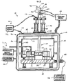
- an apparatus 10 for cathodic arc vapor deposition on a substrate 12, hereinafter referred to as a "cathodic arc coater”, having a vessel 14, means 16 for maintaining a vacuum in the vessel 14, a cathode 18, a contactor 20, an actuator 22 for selectively actuating the contactor 20 into electrical contact with the cathode 18, and means 24 for sustaining an arc of electrical energy between the cathode 18 and an anode 26.
- a coolant supply 28 maintains the apparatus 10 within acceptable temperatures by cycling coolant through cooling passages 30,32 within the vessel 14 and contactor 20.
- the means 16 for maintaining a vacuum in the vessel 14 preferably includes a mechanical rough vacuum pump 34 and a high volume diffusion-type vacuum pump 36 piped to the interior of the vessel 14. Other vacuum means may be used alternatively, however.
- the cathode 18 is positioned on a platter 38 which can be readily inserted and removed from the vessel 14. The cathode 18 is mounted in the center of the platter 38, and is electrically insulated from the platter 38. A plurality of pivotly attached substrate pedestals 39, attached to the platter 38, surround the cathode 18.
- the cathode 18 is substantially annular, having a first end surface 40, a second end surface 42, and an evaporative surface 44 and bore 46 extending between the first 40 and second 42 end surfaces.
- the end surfaces 40,42 are substantially parallel with one another.
- the material composition of the cathode 18 will depend upon the material to be deposited.
- the axial length 48 of the cathode 18 is preferably longer than the anticipated final axial length 50 of the erosion pattern 52 along the evaporative surface 44 of the cathode 18. Keeping the erosion pattern 52 between the end surfaces 40,42 minimizes the possibility that the arc will leave the evaporative surface 44 of the cathode 18.
- the contactor 20 includes a head 54 attached to a hollow shaft 56.
- the head is positioned inside the vessel 14 and the shaft 56 extends from the head 54 to outside the vessel 14.
- An insulative disk 58 electrically insulates the contactor 20 from the vessel 14.
- the contactor 20 preferably includes a cooling tube 60 coaxially positioned within the shaft 56, a coolant inlet port 62 connected to the cooling tube 60, and a coolant exit port 64 connected to the passage 32 formed between the coaxial coolant tube 60 and shaft 56.
- the coaxial arrangement between the cooling tube 60 and the shaft 56 allows coolant to flow in the cooling tube 60 and exit via the passage 32 between the shaft 56 and the cooling tube 60, or vice versa.
- the actuator 22 for selectively actuating the contactor 20 into electrical contact with the cathode 18 includes a pair of two-way actuating cylinders 66 (hydraulic or pneumatic) acting between the vessel and a shaft flange attached to the contactor shaft.
- Mechanical apparatus (not shown) may be used in place of the actuating cylinders 66.
- a commercially available controller (not shown) can be used to control the position and force of the cylinders 66 (or mechanical apparatus).
- the contactor head 54 includes a tapered end 70.
- the tapered end 70 is selectively received by a support block 72 that supports both a magnetic field generator 74 and the cathode 18.
- the actuator 22 selectively actuates the contactor head 54 into and out of contact with the support block 72.
- the magnetic field generator 74 is positioned within the bore 46 of the cathode 18, substantially aligned with the axial midpoint 41 of the cathode 18.
- the support block 72 electrically connects the contactor 20 to the cathode 18.
- An electrical insulator 76 and deflector shield 78 positioned on the side of the cathode 18 opposite the support block 72, help keep contamination and debris off the cathode end surface 40.
- the contactor head 54 includes a cup 80 and a lid 82 that houses the magnetic field generator 74.
- the cup 80 is received within the bore 46 of the cathode 18, such that the magnetic field generator 74 is substantially aligned with the axial midpoint 41 of the cathode 18.
- the cup 80 makes electrical contact with the cathode 18, thereby connecting the cathode 18 to the contactor 20.
- the actuator 22 selectively actuates the contactor head 54 into and out of contact with the cathode 18.
- FIG.4 shows mating male 84 and female 86 surfaces on the cup 80 and within the cathode bore 46, respectively.
- the mating male 84 and female 86 connection facilitates the contact necessary for an adequate electrical contact. Other connection geometries may be used alternatively.
- the contactor shaft 56 and head 54 are fabricated from an electrically conductive material such as a copper alloy.
- the magnetic field generator 74 includes an annular magnet 88, preferably segmented, which has a first 90 and second 92 end surface.
- the polar ends of the annular magnet 88 are aligned with the end surfaces 90,92; i.e., one end surface has an "N" polarity and the other has an "S" polarity.
- the magnetic field generator 74 includes a plurality of magnets 94 and a holder 96.
- the magnets 94 are held by the holder 96, and are uniformly spaced around the circumference of the cathode bore 46. Readily available commercial cylindrical magnets may be used.
- FIG.5 shows an embodiment having four (4) magnets 94 held within the holder 96, although, the number of magnets 94 can be varied to accommodate the process at hand.
- the preferred embodiment further includes apparatus 98 for rotating the magnetic field generator 74.
- the rotation apparatus 98 includes a rod 100 extending through the coolant tube 60 and into the head 54 where it connects with the magnet holder 96.
- the opposite end of the rod 100 is connected to a variable speed drive motor 102 via a drive belt 104.
- the cathodic arc coater 10 preferably includes a biasing source 106 for electrically biasing the substrates 12.
- a contact 108 electrically connects the biasing source 106 and the platter 38.
- the substrates 12, which are mechanically and electrically attached to the platter 38, are consequently electrically connected to the biasing source 106.
- Other means for electrically connecting the substrates 12 to the biasing source 106 may be used alternatively.
- Deflector shields 110 are used throughout the cathodic arc coater 10 to confine the vaporized cathode materials in the area of the substrates 12.
- the deflector shields 110 attached to the vessel 14, platter 38, and the contactor 20 also minimize undesirable material build-up on those surfaces.
- the deflector shields 110 attached to the vessel 14 are electrically connected to the vessel 14 and are made of an electrically conductive material resistant to corrosion, such as stainless steel.
- the means 24 for sustaining an arc of electrical energy between the cathode 18 and an anode 26 includes a direct current (D.C.) power supply 112.
- D.C. direct current
- the positive lead 114 of the power supply 112 is connected to the vessel 14, thereby making the vessel 14 act as an anode.
- the negative lead 116 of the power supply 112 is electrically connected to the contactor shaft 56.
- Alternative embodiments may use an anode (not shown) disposed inside the vessel 14.
- An arc initiator 118 located inside the vessel 14 is maintained at or near the electrical potential of the vessel 14. The arc initiator 118 can be moved into and out of contact with the cathode 18.
- cathodic arc coater 10 a cathode 18 is attached to the center of the platter 38 and a substrate 12 is attached to each rotatable pedestal 39 surrounding the cathode 18.
- the platter 38 is subsequently loaded into the vessel 14.
- the substrates 12 have been previously degreased and substantially cleaned, although each will likely have some molecular contaminant and oxidation remaining on its exterior surface.
- the actuating cylinders 66 subsequently actuate the contactor 20 into electrical contact with the cathode 18 and the vessel 14 is closed.
- the mechanical rough vacuum pump 34 is operated to evacuate the vessel 14 to a predetermined pressure. Once that pressure is reached, the high volume diffusion vacuum pump 36 further evacuates the vessel 14 to near vacuum conditions.
- the substrates 12 are then cleaned of any remaining contaminants and/or oxidation by a method such as "sputter cleaning".
- Sputter cleaning is a process well known in the art and will not be described in detail here. Other cleaning methods may be used alternatively.
- the contaminants are purged typically using an inert gas.
- the substrates 12 Prior to initiating an arc several steps are completed, including: (1) the substrates 12 are set to a particular bias via the biasing source 106, making them electrically attractive to positive ions emitted from the cathode 18; (2) the substrates 12 are put in motion at a particular rotational velocity; (3) the power supply 112 is set to establish an arc having a particular magnitude of current and voltage, but no arc is initiated; (4) the vacuum pumps 34,36 establish and maintain a particular vacuum pressure of gas within the vessel 14; and (5) coolant is cycled through the cooling passages 30, 32 within the vessel 14 and contactor 20. Specific process parameters will depend upon factors such as the substrate material, the material to be coated, and the desired characteristics of the coating, etc.
- the arc initiator 118 is brought into and out of contact with the evaporative surface 44 of the cathode 18, causing an arc to jump between the arc initiator 118 and the evaporative surface 44.
- the arc initiator 118 is subsequently moved a distance away from the cathode 18, preferably radially outside of the substrates 12. Once the arc initiator 118 is no longer proximate the cathode 18, the arc jumps between the cathode 18 and the deflector shields 110 electrically connected to the anodic vessel 14 (or directly to the anodic vessel 14).
- the magnetic field generator 74 positioned in the contactor 20 drives the arc along the evaporative surface 44 of the cathode 18.
- the annular magnet 88 (or magnets 94) produces a magnetic field, a portion of which runs substantially parallel to the cathode evaporate surface 44.
- FIG.3 shows an approximation of where the magnetic field lines are believed to run.
- a vector 124 representing the magnetic field extends between cathode end surfaces 40,42. The direction of the magnetic field vector depends upon the orientation of the magnet poles. In the case of multiple magnets 94, all magnet poles are oriented in like manner.
- a vector 126 representing the electric arc in contrast, extends away from the evaporative surface 44 in a substantially perpendicular direction.
- the magnetic field and the electric current of the arc create a force (the Hall effect) on the arc that drives the arc a distance around the circumference of the cathode 18.
- the dwell time of the arc at any particular cathode spot is inversely related to the Hall effect force; i.e., an increase in the Hall effect force, causes a decrease in the dwell time.
- the continuous annular magnetic field and the current drive the arc along an arc path 128 circling the evaporative surface 44 of the cathode 18.
- the individual magnetic fields collectively drive the arc along the arc path 128.
- the number of magnets 94, the relative spacing of magnetic fields emanating from magnets 94, and the intensity of those magnetic fields can be adjusted to satisfy the application at hand.
- the symmetry of the magnetic field generator 74 relative to the cathode helps increase the efficiency of the coating process by maximizing the amount of material that can be eroded from a particular cathode. Specifically, substantially aligning the magnetic field generator 74 on the axial midpoint 41 of the cathode helps promote an arc path 128 proximate the axial midpoint 41 of the cathode 18. In addition, the symmetry of the magnetic field generator 74 relative to the cathode 18 also appears to increase the parallelism of the magnetic field lines relative to the cathode evaporative surface 44.
- the erosion pattern 52 grows axially during the erosion process, thereby maximizing the amount of cathode material that can be eroded from a particular annular cathode 18 and consequently increasing the efficiency of the coating process.
- FIGS. 2 and 4 shows an eroded cathode 18 in phantom, substantially symmetrical about an arc path 128.
- rotation of the magnetic field generator 74 within the contactor 20 helps promote uniform axial and circumferential erosion of the cathode 18.
- the rotation distributes the magnetic contribution of each magnet 94 around the circumference of the cathode 18 as a function of time. It must be emphasized, however, that rotation of the magnetic field generator 74 is not required to create a circling arc.
- the magnetic field of the annular magnet 88 or individual magnetic fields of the magnets 94 collectively forces the arc to circle the cathode evaporative surface 44.
- the energy delivered by the arc causes the material at the cathode spot to vaporize, thereby liberating atoms, molecules, ions, electrons, and particles from the cathode 18.
- the biased substrates 12 attract the ions, causing them to accelerate toward the substrates 12.
- the ions strike the exterior surface of the substrates 12, attach, and collectively form a coating of the cathode material.
- the power supply 112 is turned off and the arc extinguished.
- the vessel 14 is purged with inert gas ad brought to ambient pressure.
- the contactor 20 is actuated out of contact with the cathode 18 and the platter 38 is removed from the vessel 14.
- the substrates 12 are subsequently removed from the platter 38 and new substrates 12 attached.
- the loaded platter 38 is then inserted back into the vessel 14 in the manner described earlier and the process repeated.
- the present invention at least in its preferred embodiments provides an apparatus for cathodic arc vapor deposition of material on a substrate that operates in a cost effective manner.
- FIG.4 shows a magnetic field generator 74 having a plurality of magnets 94 and a holder 96.
- the annular magnet 88 shown in FIG.2 may be used in place of the plurality of magnets 94 and holder 96.
- a protective coating may be provided which encases the magnets 94 to inhibit corrosion of the ferromagnetic centre piece and the magnets.
Landscapes
- Chemical & Material Sciences (AREA)
- Engineering & Computer Science (AREA)
- Physics & Mathematics (AREA)
- Plasma & Fusion (AREA)
- Analytical Chemistry (AREA)
- Chemical Kinetics & Catalysis (AREA)
- Materials Engineering (AREA)
- Mechanical Engineering (AREA)
- Metallurgy (AREA)
- Organic Chemistry (AREA)
- Physical Vapour Deposition (AREA)
Claims (16)
- Appareil (10) pour appliquer une matière par déposition en phase vapeur à arc cathodique sur des substrats (12), comprenant :un récipient (14) ;des moyens (16) pour maintenir un vide dans ledit récipient ;une cathode annulaire (18), ayant une première surface d'extrémité (40), une deuxième surface d'extrémité (42), une surface d'évaporation (44) et un alésage (46), dans laquelle ledit alésage et ladite surface d'évaporation s'étendent entre lesdites première et deuxième surfaces d'extrémité ;dans lequel ledit récipient est adapté pour recevoir ladite cathode annulaire destinée à être disposée dans le récipient radialement à l'intérieur de celui-ci et alignée avec les substrats ;des moyens (24) pour entretenir sélectivement un arc d'énergie électrique entre ladite cathode et une anode (26) ;un contacteur (20), connecté électriquement à une ou ladite alimentation électrique (112), ledit contacteur comprenantune tête (54), positionnée à l'intérieur dudit récipient (14), etun axe creux (56), fixé à ladite tête, s'étendant de ladite tête à l'extérieur dudit récipient ;un actuateur (22), dans lequel ledit actuateur actionne sélectivement ledit contacteur en contact électrique avec ladite cathode (18) et connecte ainsi électriquement ladite cathode à ladite alimentation électrique ; etdes moyens pour commander ledit arc autour de ladite surface d'évaporation, qui sont positionnés à l'intérieur dudit alésage de cathode en service, et produisent un champ magnétique qui s'étend sensiblement parallèlement à ladite surface d'évaporation ;dans lequel ledit arc d'énergie électrique s'étendant entre ladite cathode et ladite anode libère une portion de ladite cathode qui est ensuite déposée sur le substrat situé radialement à l'extérieur de ladite cathode.
- Appareil (10) selon la revendication 1, dans lequel lesdits moyens (24) pour entretenir un arc d'énergie électrique entre ladite cathode (18) et ladite anode (26) comprennent :une alimentation électrique (112), ayant un conducteur positif (114) et un conducteur négatif (116) ;dans lequel ledit conducteur négatif de ladite alimentation électrique est connecté électriquement à ladite cathode et ledit conducteur positif est connecté électriquement au dit récipient (14), en faisant ainsi en sorte que le récipient agisse comme ladite anode ; etdans lequel la cathode est isolée électriquement par rapport au dit récipient.
- Appareil (10) selon la revendication 1 ou 2, dans lequel lesdits moyens pour commander ledit arc comprennent un générateur de champ magnétique (74) ayant une pluralité d'aimants (94) et un support (96), et
dans lequel ledit générateur de champ magnétique est positionné dans ledit alésage de cathode (46), et est sensiblement aligné avec un milieu axial de ladite cathode annulaire (18). - Appareil (10) selon la revendication 3, dans lequel ledit support (96) supporte lesdits aimants (94) dans un agencement uniformément espacé autour d'une circonférence dudit alésage (46).
- Appareil (10) selon la revendication 1 ou 2, dans lequel lesdits moyens pour commander ledit arc comprennent un générateur de champ magnétique (74) ayant un aimant annulaire (88), et
dans lequel ledit générateur de champ magnétique est positionné dans ledit alésage de cathode (46) et est sensiblement aligné avec un milieu axial de ladite cathode annulaire (18). - Appareil (10) selon la revendication 5, dans lequel ledit aimant annulaire (88) a une pluralité de segments.
- Appareil (10) selon l'une quelconque des revendications 3 à 6, comprenant en outre :un revêtement protecteur (110), ledit revêtement englobant ledit ou lesdits aimants (88 ; 94) pour empêcher une corrosion de ladite pièce centrale ferromagnétique et desdits aimants.
- Appareil (10) selon l'une quelconque des revendications précédentes, dans lequel ledit contacteur (20) comprend en outre des moyens pour refroidir ledit axe et ladite tête.
- Appareil (10) selon la revendication 8, dans lequel lesdits moyens de refroidissement comprennent :un tube de refroidissement (60) , positionné à l'intérieur dudit axe (56), dans lequel un passage (32) est formé entre ledit tube de refroidissement et ledit axe ;une source de réfrigérant, raccordée au dit tube de refroidissement et au dit passage, pour délivrer un réfrigérant dans ledit contacteur (20).
- Appareil selon la revendication 9, comprenant en outre :un plateau (38) ;dans lequel un ou plusieurs substrats (12) sont connectés au dit plateau ; etdans lequel ladite cathode (18) est montée sur ledit plateau et isolée électriquement par rapport au dit plateau ;dans lequel ledit plateau est chargé dans ledit récipient (14) avant la déposition et retiré ensuite.
- Appareil selon la revendication 10, dans lequel ledit plateau (38) comprend en outre :une pluralité de socles (39), fixés de manière pivotante sur ledit plateau, et un ou plusieurs desdits substrats (12) sont fixés sur chaque socle ;dans lequel lesdits socles et lesdits substrats fixés peuvent être pivotés pour changer l'orientation par rapport à ladite cathode (18).
- Appareil selon l'une quelconque des revendications précédentes, dans lequel lesdits moyens pour commander ledit arc autour de ladite surface d'évaporation (44) comprennent :un générateur de champ magnétique (74) ayant une pluralité d'aimants (94) et un support (96), disposé dans ladite tête (54) ;dans lequel ladite tête est actionnée sélectivement dans ledit alésage de cathode (46) vers une position dans laquelle ledit générateur de champ magnétique est sensiblement aligné avec un milieu axial de ladite cathode annulaire (18).
- Appareil selon la revendication 12, dans lequel ledit support (96) supporte lesdits aimants (94) dans un agencement uniformément espacé autour d'une circonférence dudit alésage (46).
- Appareil selon la revendication 12 ou 13, comprenant en outre :des moyens (98) pour faire tourner ledit générateur de champ magnétique (74) dans ladite tête (54).
- Appareil selon l'une quelconque des revendications précédentes, dans lequel lesdits moyens pour commander ledit arc autour de ladite surface d'évaporation (44) comprennent :un générateur de champ magnétique (74) ayant un aimant annulaire (88), disposé dans ladite tête (54) ;dans lequel ladite tête est actionnée sélectivement dans ledit alésage de cathode (46) vers une position où ledit générateur de champ magnétique est sensiblement aligné avec un milieu axial de ladite cathode annulaire (18).
- Appareil selon la revendication 15, dans lequel ledit aimant annulaire (88) a une pluralité de segments.
Applications Claiming Priority (2)
| Application Number | Priority Date | Filing Date | Title |
|---|---|---|---|
| US919131 | 1997-08-30 | ||
| US08/919,131 US5972185A (en) | 1997-08-30 | 1997-08-30 | Cathodic arc vapor deposition apparatus (annular cathode) |
Publications (3)
| Publication Number | Publication Date |
|---|---|
| EP0905272A2 EP0905272A2 (fr) | 1999-03-31 |
| EP0905272A3 EP0905272A3 (fr) | 2000-12-06 |
| EP0905272B1 true EP0905272B1 (fr) | 2006-07-26 |
Family
ID=25441556
Family Applications (1)
| Application Number | Title | Priority Date | Filing Date |
|---|---|---|---|
| EP98306938A Expired - Lifetime EP0905272B1 (fr) | 1997-08-30 | 1998-08-28 | Appareil de déposition en phase vapeur à arc cathodique (cathode annulaire) |
Country Status (6)
| Country | Link |
|---|---|
| US (1) | US5972185A (fr) |
| EP (1) | EP0905272B1 (fr) |
| JP (1) | JPH11140630A (fr) |
| KR (1) | KR100569044B1 (fr) |
| DE (1) | DE69835324T2 (fr) |
| SG (1) | SG67548A1 (fr) |
Families Citing this family (28)
| Publication number | Priority date | Publication date | Assignee | Title |
|---|---|---|---|---|
| EP1109641A4 (fr) * | 1998-07-21 | 2004-10-06 | Commw Scient Ind Res Org | Procede et appareil de production de vapeurs de materiaux |
| JP3104701B1 (ja) * | 1999-08-18 | 2000-10-30 | 日新電機株式会社 | アーク式蒸発源 |
| US6936145B2 (en) * | 2002-02-28 | 2005-08-30 | Ionedge Corporation | Coating method and apparatus |
| KR100811446B1 (ko) | 2003-11-17 | 2008-03-07 | 동부일렉트로닉스 주식회사 | 이온주입장치용 캐소우드 바이어스 와이어 구조 |
| US7084573B2 (en) * | 2004-03-05 | 2006-08-01 | Tokyo Electron Limited | Magnetically enhanced capacitive plasma source for ionized physical vapor deposition |
| US8241468B2 (en) | 2004-12-13 | 2012-08-14 | United Technologies Corporation | Method and apparatus for cathodic arc deposition of materials on a substrate |
| US7214409B1 (en) | 2005-12-21 | 2007-05-08 | United Technologies Corporation | High strength Ni-Pt-Al-Hf bondcoat |
| US20070138019A1 (en) * | 2005-12-21 | 2007-06-21 | United Technologies Corporation | Platinum modified NiCoCrAlY bondcoat for thermal barrier coating |
| US20100143232A1 (en) * | 2006-06-21 | 2010-06-10 | Benedict James Costello | Metal binary and ternary compounds produced by cathodic arc deposition |
| EP3236524A1 (fr) | 2007-02-14 | 2017-10-25 | Proteus Digital Health, Inc. | Source d'énergie intégrée au corps ayant une électrode de surface élevée |
| US8088260B2 (en) * | 2007-08-14 | 2012-01-03 | United Technologies Corporation | Puck for cathodic arc coating with continuous groove to control arc |
| CN101861659A (zh) * | 2007-12-12 | 2010-10-13 | 新港有限公司 | 性能提高的光学镀膜半导体器件及相关生产方法 |
| US8641963B2 (en) | 2008-07-08 | 2014-02-04 | United Technologies Corporation | Economic oxidation and fatigue resistant metallic coating |
| US20120193227A1 (en) * | 2011-02-02 | 2012-08-02 | Tryon Brian S | Magnet array for a physical vapor deposition system |
| US9153422B2 (en) | 2011-08-02 | 2015-10-06 | Envaerospace, Inc. | Arc PVD plasma source and method of deposition of nanoimplanted coatings |
| US9359669B2 (en) | 2011-12-09 | 2016-06-07 | United Technologies Corporation | Method for improved cathodic arc coating process |
| US9506140B2 (en) | 2013-03-15 | 2016-11-29 | United Technologies Corporation | Spallation-resistant thermal barrier coating |
| US9786474B2 (en) | 2013-10-08 | 2017-10-10 | United Technologies Corporation | Cathodic arc deposition apparatus and method |
| WO2015077163A1 (fr) | 2013-11-19 | 2015-05-28 | United Technologies Corporation | Article possédant un revêtement de composition variable |
| US20170016745A1 (en) * | 2014-03-24 | 2017-01-19 | Panasonic Intellectual Property Management Co., Ltd. | Magnetic sensor |
| US10094890B2 (en) * | 2014-10-09 | 2018-10-09 | Panasonic Intellectual Property Management Co., Ltd. | Magnetic sensor |
| US10371244B2 (en) | 2015-04-09 | 2019-08-06 | United Technologies Corporation | Additive manufactured gear for a geared architecture gas turbine engine |
| US20170198601A1 (en) | 2016-01-12 | 2017-07-13 | United Technologies Corporation | Internally cooled ni-base superalloy component with spallation-resistant tbc system |
| US20210147974A1 (en) * | 2017-06-08 | 2021-05-20 | Board Of Trustees Of Michigan State University | Magnetic-field-assisted plasma coating system |
| CN108642452B (zh) * | 2018-06-08 | 2020-07-03 | 芜湖市亿仑电子有限公司 | 一种电容器金属化薄膜加工真空镀膜机 |
| US12048910B2 (en) | 2018-07-11 | 2024-07-30 | Board Of Trustees Of Michigan State University | Vertically oriented plasma reactor |
| US12224165B2 (en) | 2019-12-06 | 2025-02-11 | Board Of Trustees Of Michigan State University | Magnetic-field-assisted plasma coating system |
| CN117966103B (zh) * | 2024-02-04 | 2024-06-18 | 浙江晟霖益嘉科技有限公司 | 一种蒸发真空设备生产线 |
Family Cites Families (41)
| Publication number | Priority date | Publication date | Assignee | Title |
|---|---|---|---|---|
| US3836451A (en) * | 1968-12-26 | 1974-09-17 | A Snaper | Arc deposition apparatus |
| US3625848A (en) * | 1968-12-26 | 1971-12-07 | Alvin A Snaper | Arc deposition process and apparatus |
| US3793179A (en) * | 1971-07-19 | 1974-02-19 | L Sablev | Apparatus for metal evaporation coating |
| US3783231A (en) * | 1972-03-22 | 1974-01-01 | V Gorbunov | Apparatus for vacuum-evaporation of metals under the action of an electric arc |
| US4673480A (en) * | 1980-05-16 | 1987-06-16 | Varian Associates, Inc. | Magnetically enhanced sputter source |
| US4609564C2 (en) * | 1981-02-24 | 2001-10-09 | Masco Vt Inc | Method of and apparatus for the coating of a substrate with material electrically transformed into a vapor phase |
| AT376460B (de) * | 1982-09-17 | 1984-11-26 | Kljuchko Gennady V | Plasmalichtbogeneinrichtung zum auftragen von ueberzuegen |
| US4673477A (en) * | 1984-03-02 | 1987-06-16 | Regents Of The University Of Minnesota | Controlled vacuum arc material deposition, method and apparatus |
| US4724058A (en) * | 1984-08-13 | 1988-02-09 | Vac-Tec Systems, Inc. | Method and apparatus for arc evaporating large area targets |
| NL8700620A (nl) * | 1987-03-16 | 1988-10-17 | Hauzer Holding | Kathode boogverdampingsinrichting alsmede werkwijze voor het bedrijven daarvan. |
| EP0298157B1 (fr) * | 1987-06-29 | 1992-09-02 | Hauzer Holding B.V. | Méthode et appareil pour revêtir des cavités d'objets |
| US4904362A (en) * | 1987-07-24 | 1990-02-27 | Miba Gleitlager Aktiengesellschaft | Bar-shaped magnetron or sputter cathode arrangement |
| EP0334204B1 (fr) * | 1988-03-23 | 1995-04-19 | Balzers Aktiengesellschaft | Procédé et dispositif de revêtement d'objets |
| US5011638A (en) * | 1988-06-17 | 1991-04-30 | Vapor Technologies, Inc. | Method of making open-pore structures |
| US4924135A (en) * | 1988-07-18 | 1990-05-08 | Vapor Technologies Inc. | Electrode for vapor deposition and vapor-deposition method using same |
| US4869203A (en) * | 1988-07-18 | 1989-09-26 | Vapor Technologies Inc. | Apparatus for coating a metal gas-pressure bottle or tank |
| US4978556A (en) * | 1988-07-18 | 1990-12-18 | Vapor Technologies Inc. | Electrode for vapor deposition and vapor-deposition method using same |
| US4859489A (en) * | 1988-07-18 | 1989-08-22 | Vapor Technologies Inc. | Method of coating a metal gas-pressure bottle or tank |
| US5234561A (en) * | 1988-08-25 | 1993-08-10 | Hauzer Industries Bv | Physical vapor deposition dual coating process |
| US4942844A (en) * | 1988-11-25 | 1990-07-24 | Vapor Technologies Inc. | High penetration deposition process and apparatus |
| US4927515A (en) * | 1989-01-09 | 1990-05-22 | The Board Of Trustees Of The Leland Stanford Junior University | Circular magnetron sputtering device |
| US5045344A (en) * | 1989-11-16 | 1991-09-03 | Vapor Technologies, Inc. | Method of making reflective articles |
| US5037522B1 (en) * | 1990-07-24 | 1996-07-02 | Vergason Technology Inc | Electric arc vapor deposition device |
| FR2670218B1 (fr) * | 1990-12-06 | 1993-02-05 | Innovatique Sa | Procede de traitement de metaux par depot de matiere, et pour la mise en óoeuvre dudit procede. |
| US5126030A (en) * | 1990-12-10 | 1992-06-30 | Kabushiki Kaisha Kobe Seiko Sho | Apparatus and method of cathodic arc deposition |
| US5269898A (en) * | 1991-03-20 | 1993-12-14 | Vapor Technologies, Inc. | Apparatus and method for coating a substrate using vacuum arc evaporation |
| JP2758999B2 (ja) * | 1991-04-10 | 1998-05-28 | 株式会社神戸製鋼所 | 真空アーク蒸着装置 |
| CA2065581C (fr) * | 1991-04-22 | 2002-03-12 | Andal Corp. | Methode de deposition physique en phase vapeur activee par plasma, et appareil connexe |
| EP0516425B1 (fr) * | 1991-05-29 | 1998-08-26 | KABUSHIKI KAISHA KOBE SEIKO SHO also known as Kobe Steel Ltd. | Système de dépÔt par pulvérisation cathodique et une méthode de commande pour ce système |
| JPH0673538A (ja) * | 1992-05-26 | 1994-03-15 | Kobe Steel Ltd | アークイオンプレーティング装置 |
| US5306408A (en) * | 1992-06-29 | 1994-04-26 | Ism Technologies, Inc. | Method and apparatus for direct ARC plasma deposition of ceramic coatings |
| US5279723A (en) * | 1992-07-30 | 1994-01-18 | As Represented By The United States Department Of Energy | Filtered cathodic arc source |
| US5282944A (en) * | 1992-07-30 | 1994-02-01 | The United States Of America As Represented By The United States Department Of Energy | Ion source based on the cathodic arc |
| US5441624A (en) * | 1992-08-25 | 1995-08-15 | Northeastern University | Triggered vacuum anodic arc |
| US5730847A (en) * | 1993-03-15 | 1998-03-24 | Kabushiki Kaisha Kobeseikosho | Arc ion plating device and arc ion plating system |
| US5317235A (en) * | 1993-03-22 | 1994-05-31 | Ism Technolog | Magnetically-filtered cathodic arc plasma apparatus |
| JP3774472B2 (ja) * | 1994-02-17 | 2006-05-17 | ユナイテッド テクノロジーズ コーポレイション | チタン合金のための耐酸化性コーティング |
| US5480527A (en) * | 1994-04-25 | 1996-01-02 | Vapor Technologies, Inc. | Rectangular vacuum-arc plasma source |
| US5468363A (en) * | 1994-04-25 | 1995-11-21 | Regents Of The University Of California | Magnetic-cusp, cathodic-arc source |
| US5518597A (en) * | 1995-03-28 | 1996-05-21 | Minnesota Mining And Manufacturing Company | Cathodic arc coating apparatus and method |
| US5588975A (en) * | 1995-05-25 | 1996-12-31 | Si Diamond Technology, Inc. | Coated grinding tool |
-
1997
- 1997-08-30 US US08/919,131 patent/US5972185A/en not_active Expired - Lifetime
-
1998
- 1998-08-27 SG SG1998003324A patent/SG67548A1/en unknown
- 1998-08-28 EP EP98306938A patent/EP0905272B1/fr not_active Expired - Lifetime
- 1998-08-28 DE DE69835324T patent/DE69835324T2/de not_active Expired - Lifetime
- 1998-08-29 KR KR1019980035353A patent/KR100569044B1/ko not_active Expired - Fee Related
- 1998-08-31 JP JP10245460A patent/JPH11140630A/ja active Pending
Also Published As
| Publication number | Publication date |
|---|---|
| DE69835324D1 (de) | 2006-09-07 |
| KR100569044B1 (ko) | 2006-06-21 |
| EP0905272A3 (fr) | 2000-12-06 |
| KR19990024031A (ko) | 1999-03-25 |
| JPH11140630A (ja) | 1999-05-25 |
| SG67548A1 (en) | 1999-09-21 |
| US5972185A (en) | 1999-10-26 |
| EP0905272A2 (fr) | 1999-03-31 |
| DE69835324T2 (de) | 2007-08-23 |
Similar Documents
| Publication | Publication Date | Title |
|---|---|---|
| US5972185A (en) | Cathodic arc vapor deposition apparatus (annular cathode) | |
| US6036828A (en) | Apparatus for steering the arc in a cathodic arc coater | |
| EP0899772B1 (fr) | Appareil de revêtement à arc cathodique | |
| US4673477A (en) | Controlled vacuum arc material deposition, method and apparatus | |
| US20110073471A1 (en) | Method and apparatus for cathodic arc ion plasma deposition | |
| JPH01272765A (ja) | スパッタ被覆装置およびその被覆方法 | |
| KR20140143352A (ko) | 여과된 음극 아크 증착 장치 및 방법 | |
| US6009829A (en) | Apparatus for driving the arc in a cathodic arc coater | |
| US6936145B2 (en) | Coating method and apparatus | |
| CA1247043A (fr) | Methode et dispositif de chargement d'une surface a l'arc sous vide | |
| EP0544831B1 (fr) | Dispositiv de pulverisation cathodique et procede de pulverisation cathodique d'amelioration de l'uniformite de repartition du flux ionique sur un substrat | |
| CA2093635C (fr) | Methode et appareil de pulverisation magnetron d'un revetement avec cathode aimantee rotative | |
| EP0899773B1 (fr) | Appareil de revêtement à arc cathodique avec un dispositif de conduite de l'arc | |
| US8241468B2 (en) | Method and apparatus for cathodic arc deposition of materials on a substrate | |
| GB2255105A (en) | Dual magnetron/cathodic arc vapour source | |
| RU2782416C1 (ru) | Магнетронная распылительная система | |
| US20090242397A1 (en) | Systems for controlling cathodic arc discharge | |
| EP0848081A2 (fr) | Méthode et dispositif de dépÔt physique en phase vapeur | |
| WO1996030928A1 (fr) | Source de plasma | |
| MXPA05013515A (en) | Method and apparatus for cathodic arc deposition of materials on a substrate |
Legal Events
| Date | Code | Title | Description |
|---|---|---|---|
| PUAI | Public reference made under article 153(3) epc to a published international application that has entered the european phase |
Free format text: ORIGINAL CODE: 0009012 |
|
| AK | Designated contracting states |
Kind code of ref document: A2 Designated state(s): DE FR GB |
|
| AX | Request for extension of the european patent |
Free format text: AL;LT;LV;MK;RO;SI |
|
| PUAL | Search report despatched |
Free format text: ORIGINAL CODE: 0009013 |
|
| AK | Designated contracting states |
Kind code of ref document: A3 Designated state(s): AT BE CH CY DE DK ES FI FR GB GR IE IT LI LU MC NL PT SE |
|
| AX | Request for extension of the european patent |
Free format text: AL;LT;LV;MK;RO;SI |
|
| 17P | Request for examination filed |
Effective date: 20010306 |
|
| 17Q | First examination report despatched |
Effective date: 20010425 |
|
| AKX | Designation fees paid |
Free format text: DE FR GB |
|
| GRAP | Despatch of communication of intention to grant a patent |
Free format text: ORIGINAL CODE: EPIDOSNIGR1 |
|
| GRAS | Grant fee paid |
Free format text: ORIGINAL CODE: EPIDOSNIGR3 |
|
| GRAA | (expected) grant |
Free format text: ORIGINAL CODE: 0009210 |
|
| AK | Designated contracting states |
Kind code of ref document: B1 Designated state(s): DE FR GB |
|
| REG | Reference to a national code |
Ref country code: GB Ref legal event code: FG4D |
|
| REF | Corresponds to: |
Ref document number: 69835324 Country of ref document: DE Date of ref document: 20060907 Kind code of ref document: P |
|
| ET | Fr: translation filed | ||
| PLBE | No opposition filed within time limit |
Free format text: ORIGINAL CODE: 0009261 |
|
| STAA | Information on the status of an ep patent application or granted ep patent |
Free format text: STATUS: NO OPPOSITION FILED WITHIN TIME LIMIT |
|
| 26N | No opposition filed |
Effective date: 20070427 |
|
| PGFP | Annual fee paid to national office [announced via postgrant information from national office to epo] |
Ref country code: FR Payment date: 20100824 Year of fee payment: 13 |
|
| REG | Reference to a national code |
Ref country code: FR Ref legal event code: ST Effective date: 20120430 |
|
| PG25 | Lapsed in a contracting state [announced via postgrant information from national office to epo] |
Ref country code: FR Free format text: LAPSE BECAUSE OF NON-PAYMENT OF DUE FEES Effective date: 20110831 |
|
| PGFP | Annual fee paid to national office [announced via postgrant information from national office to epo] |
Ref country code: GB Payment date: 20120822 Year of fee payment: 15 |
|
| GBPC | Gb: european patent ceased through non-payment of renewal fee |
Effective date: 20130828 |
|
| PG25 | Lapsed in a contracting state [announced via postgrant information from national office to epo] |
Ref country code: GB Free format text: LAPSE BECAUSE OF NON-PAYMENT OF DUE FEES Effective date: 20130828 |
|
| PGFP | Annual fee paid to national office [announced via postgrant information from national office to epo] |
Ref country code: DE Payment date: 20150722 Year of fee payment: 18 |
|
| REG | Reference to a national code |
Ref country code: DE Ref legal event code: R119 Ref document number: 69835324 Country of ref document: DE |
|
| PG25 | Lapsed in a contracting state [announced via postgrant information from national office to epo] |
Ref country code: DE Free format text: LAPSE BECAUSE OF NON-PAYMENT OF DUE FEES Effective date: 20170301 |