EP0905341A1 - Ferrure de meuble pour fixation sans outil dans un orifice d'un élément de meuble, en particulier élément de fixation de charnières de meuble pour porte de meuble - Google Patents
Ferrure de meuble pour fixation sans outil dans un orifice d'un élément de meuble, en particulier élément de fixation de charnières de meuble pour porte de meuble Download PDFInfo
- Publication number
- EP0905341A1 EP0905341A1 EP98116507A EP98116507A EP0905341A1 EP 0905341 A1 EP0905341 A1 EP 0905341A1 EP 98116507 A EP98116507 A EP 98116507A EP 98116507 A EP98116507 A EP 98116507A EP 0905341 A1 EP0905341 A1 EP 0905341A1
- Authority
- EP
- European Patent Office
- Prior art keywords
- recess
- flange
- bracket body
- door wing
- furniture
- Prior art date
- Legal status (The legal status is an assumption and is not a legal conclusion. Google has not performed a legal analysis and makes no representation as to the accuracy of the status listed.)
- Granted
Links
Images


Classifications
-
- A—HUMAN NECESSITIES
- A47—FURNITURE; DOMESTIC ARTICLES OR APPLIANCES; COFFEE MILLS; SPICE MILLS; SUCTION CLEANERS IN GENERAL
- A47B—TABLES; DESKS; OFFICE FURNITURE; CABINETS; DRAWERS; GENERAL DETAILS OF FURNITURE
- A47B95/00—Fittings for furniture
-
- E—FIXED CONSTRUCTIONS
- E05—LOCKS; KEYS; WINDOW OR DOOR FITTINGS; SAFES
- E05D—HINGES OR SUSPENSION DEVICES FOR DOORS, WINDOWS OR WINGS
- E05D5/00—Construction of single parts, e.g. the parts for attachment
- E05D5/02—Parts for attachment, e.g. flaps
- E05D5/08—Parts for attachment, e.g. flaps of cylindrical shape
-
- F—MECHANICAL ENGINEERING; LIGHTING; HEATING; WEAPONS; BLASTING
- F16—ENGINEERING ELEMENTS AND UNITS; GENERAL MEASURES FOR PRODUCING AND MAINTAINING EFFECTIVE FUNCTIONING OF MACHINES OR INSTALLATIONS; THERMAL INSULATION IN GENERAL
- F16B—DEVICES FOR FASTENING OR SECURING CONSTRUCTIONAL ELEMENTS OR MACHINE PARTS TOGETHER, e.g. NAILS, BOLTS, CIRCLIPS, CLAMPS, CLIPS OR WEDGES; JOINTS OR JOINTING
- F16B12/00—Jointing of furniture or the like, e.g. hidden from exterior
- F16B12/10—Jointing of furniture or the like, e.g. hidden from exterior using pegs, bolts, tenons, clamps, clips, or the like
- F16B12/12—Jointing of furniture or the like, e.g. hidden from exterior using pegs, bolts, tenons, clamps, clips, or the like for non-metal furniture parts, e.g. made of wood, of plastics
- F16B12/20—Jointing of furniture or the like, e.g. hidden from exterior using pegs, bolts, tenons, clamps, clips, or the like for non-metal furniture parts, e.g. made of wood, of plastics using clamps, clips, wedges, sliding bolts, or the like
-
- A—HUMAN NECESSITIES
- A47—FURNITURE; DOMESTIC ARTICLES OR APPLIANCES; COFFEE MILLS; SPICE MILLS; SUCTION CLEANERS IN GENERAL
- A47B—TABLES; DESKS; OFFICE FURNITURE; CABINETS; DRAWERS; GENERAL DETAILS OF FURNITURE
- A47B2220/00—General furniture construction, e.g. fittings
- A47B2220/0061—Accessories
- A47B2220/0069—Hinges
- A47B2220/0072—Hinges for furniture
-
- E—FIXED CONSTRUCTIONS
- E05—LOCKS; KEYS; WINDOW OR DOOR FITTINGS; SAFES
- E05D—HINGES OR SUSPENSION DEVICES FOR DOORS, WINDOWS OR WINGS
- E05D7/00—Hinges or pivots of special construction
- E05D7/12—Hinges or pivots of special construction to allow easy detachment of the hinge from the wing or the frame
- E05D7/123—Hinges or pivots of special construction to allow easy detachment of the hinge from the wing or the frame specially adapted for cabinets or furniture
- E05D7/125—Hinges or pivots of special construction to allow easy detachment of the hinge from the wing or the frame specially adapted for cabinets or furniture the hinge having two or more pins
-
- E—FIXED CONSTRUCTIONS
- E05—LOCKS; KEYS; WINDOW OR DOOR FITTINGS; SAFES
- E05Y—INDEXING SCHEME ASSOCIATED WITH SUBCLASSES E05D AND E05F, RELATING TO CONSTRUCTION ELEMENTS, ELECTRIC CONTROL, POWER SUPPLY, POWER SIGNAL OR TRANSMISSION, USER INTERFACES, MOUNTING OR COUPLING, DETAILS, ACCESSORIES, AUXILIARY OPERATIONS NOT OTHERWISE PROVIDED FOR, APPLICATION THEREOF
- E05Y2900/00—Application of doors, windows, wings or fittings thereof
- E05Y2900/20—Application of doors, windows, wings or fittings thereof for furniture, e.g. cabinets
Definitions
- the invention relates to a furniture fitting part for the tool-free Installation in a recess in a plate-shaped Furniture part, with an undersize opposite the recess dimensioned holding part that can be inserted into the recess, a radially protruding, Feasible in contact with the outside of the furniture part Flange is provided, and with an assembled state clamping element lying within the recess, which by a arranged on the mounting flange of Hand-operated handle is essentially radially jammed Spreading system against the wall of the recess is.
- Both clamping elements are like a circlip flat spiral spring biased into the release position.
- This spiral spring is on its outer, the wall of the recess facing lateral edge areas with tapered Provide projections when pivoting the clamping elements penetrate into the wall of the recess and so an additional positive locking of the door wing stop part ensure against leakage from the recess.
- This door wing stop part has been put into practice extremely proven. Due to the relatively complex structure is the manufacturing effort and are therefore also Manufacturing costs, however, are considerable.
- the invention is based on the object a furniture fitting part, in particular a door wing stop part of the kind in question here, which, thanks to a simplified structure, makes it cheaper Manufacture allows, without the simple and quick, tool-free assembly and disassembly or the Secure anchoring in the assembled state is impaired becomes.
- the clamping element as a part of the height and part of the circumference of the holding part extending and in Extension area essentially to the contour of the recess adapted bracket body with attached on both sides, lever projections lying on the outside of the holding part is formed, which is pivotable about a common axis hinged to the flange or near the flange on the holding part are that the handle on the top of the Flange around a parallel to the pivot axis of the bracket body running pivot axis between a pivoted up from the flange and a position on the flange is pivotally articulated, and that the handle in the area their pivotable mounting on the flange each has a cam shoulder protruding under the flange, provided on one each on the bracket body lever lugs Attack the cam counter surface.
- a door wing stop for The furniture fitting part can hinge certain further training be designed so that the holding part in a known per se Way as a trough-like flattened on both sides Pot part with attached to its upper edge and in the intended mounting position on the back of the the respective door leaf lying on top and the door leaf recess at least partially covering, in one piece Mounting flange is formed, the metallic Temple body in the area in the intended Installation position within the door opening opposite the adjacent edge of the door leaf Wall area of the pot part is provided and around a common axis pivotable on the mounting flange or flat lever lugs hinged to the pot part via the Guided outside of the side flats of the trough part are.
- the bracket body can at least in its, the contour the wall of the recess adapted part in a cutout be arranged in the wall of the pot part.
- this part of the bracket body can also be used be arranged on the outside of the wall of the pot part.
- the bracket body expediently has in its clamping system can be brought to the wall of the door opening Area an arcuate section whose outer radius the door leaf recess intended for receiving the pot part corresponds.
- bracket body on its outside with the wall intended for receiving the pot part
- the bracket body is preferably a stamped and pressed part formed from sheet metal using a material which is then - e.g. through suitable heat treatment - Can be designed to be resilient when mounted in the pot section is.
- the pot part and the mounting flange are also preferred an integral stamped-pressed part made of sheet metal.
- the lever approaches on the bracket body expediently each one that penetrates a slot in the mounting flange and encompassing a boundary edge of the respective slot Hook on.
- the two hook approaches cause So the pivotable mounting of the bracket body on the mounting flange.
- the handle the shape of a low U-shaped bracket plate, which in the Area of the free ends of their two U-legs each is pivotally mounted on the mounting flange.
- the handle is advantageous as an integral die-cast part made of metal, to which also by each performed a window in the mounting flange Cam lugs are integrally molded.
- a pointed or sharpened projection e.g. in the form of a circumferential direction Rib, provided, which in response to the the installation of the door wing stop part between the bracket body and the wall of the recess occurring clamping forces on the side opposite the bracket body also digs into the wall of the recess. or dig in.
- bracket body at a required Disassembly when swiveling the handle up actually from its clamped position to the release position is transferred, it is also recommended to at the Handle and / or the restoring element to provide, which the bracket body when pivoted in the swung up position inevitably from the jamming Attachment to the wall of the recess in one of the Withdraw the clamped position of the released position.
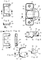
- FIG. 1 shows schematically one in its entirety at 20 designated furniture hinge shown, in which a formed as an elongated support arm 22 on the side wall a closable, adjustable body stop over one of two hinge links, one of which only the one hinge link 24 is shown formed hinge mechanism with one in the manner according to the invention trained, sunk in a recess in the back one - not shown - door wing mountable Door wing stop part 26 is coupled.
- the door wing stop 26 has a - in the case shown made of sheet metal manufactured by punch-press - hinge or Socket 28 on which in the connection below designed with the figures 5 and 6 described can be, which by the in connection with the Figures 11 and 12 described clamping element on or in the door leaf is held releasably.
- door wing stop member 26 is in the figures 2 to 4 and has an insertion pot 28, which sunk out of the actual in the - not shown - Recess of the door leaf insertable pot part 30 and one arranged on its upper edge, on both sides composed laterally protruding mounting flange 32, its underside facing the door leaf when mounted Insert 26 sits on the inner surface of the door leaf.
- On the top of the mounting flange is a handle 36 in the form of a low, top view U-shaped bracket plate provided in the figures 7 to 10 is shown separately.
- Pot part to be mounted in the back of a door leaf 30 of the actual insertion pot 28 has the shape a laterally flattened tub in the side walls Holes 38 and 40 are punched in which the ends the hinge arm of the joint mechanism on the insertion side pivotable bearing pins 42, 44 (Fig. 1) are riveted.
- the mounting flange 32 engages laterally over the generally circularly delimited plan view Recess in the door wing and therefore covers the one there existing between the pot part 30 and the wall of the recess Space. Im to the neighboring edge of the door leaf pointing - in Fig.
- this space is from the upper area Edge of the pot part folded and according to the diameter the recess of sections delimited in a circular section 46 from the sheet material of the hinge cup 28 closed so that the recess in the door leaf when mounted Door wing stop part is completely covered.
- bracket body made of resilient sheet metal 50 each extend flat hook lugs 56 upwards, which in part through slots 58 in the mounting flange are passed and a boundary edge of the respective slot 58.
- the lever lugs 52 At a distance and below the hook lugs 56 is the upper boundary edge the lever lugs 52 as cam counter surface 60 for each one at the following in connection with Figures 7 to 10 still described handle 36 provided cam approach 62 trained. It can already be seen that the best as intended in the manner recognizable in FIGS. 3 and 4 bracket body 50 mounted in cutout 48 through the hook attachments suspended in the slots 58 pivotable, i.e. can be pushed out of the cutout 48 or is retractably stored in it.
- the door wing stop part shown in Figures 13 and 14 is compared to the door leaf stop part described above 26 only with regard to an additional coupling of the bracket body 50 and the handle 36 such that the bracket body 50 when swiveling the handle 36 inevitably from the radially swung out clamping position into the swung back Release position is transferred, trained.
- This training is described below while regarding the matching design of both Embodiments to avoid repetitions to the preceding description of that in FIGS 4 door wing stop part described can, especially since the same parts in the drawing figures too same reference numerals are assigned.
Landscapes
- Engineering & Computer Science (AREA)
- General Engineering & Computer Science (AREA)
- Mechanical Engineering (AREA)
- Hinges (AREA)
- Pivots And Pivotal Connections (AREA)
Applications Claiming Priority (2)
| Application Number | Priority Date | Filing Date | Title |
|---|---|---|---|
| DE29717508U | 1997-09-30 | ||
| DE29717508U DE29717508U1 (de) | 1997-09-30 | 1997-09-30 | Möbelbeschlagteil zur werkzeuglosen Montage in einer Ausnehmung in einem Möbelteil, insbesondere Türflügel-Anschlagteil für Möbelscharniere |
Publications (2)
| Publication Number | Publication Date |
|---|---|
| EP0905341A1 true EP0905341A1 (fr) | 1999-03-31 |
| EP0905341B1 EP0905341B1 (fr) | 2002-03-27 |
Family
ID=8046697
Family Applications (1)
| Application Number | Title | Priority Date | Filing Date |
|---|---|---|---|
| EP98116507A Expired - Lifetime EP0905341B1 (fr) | 1997-09-30 | 1998-09-01 | Ferrure de meuble pour fixation sans outil dans un orifice d'un élément de meuble, en particulier élément de fixation de charnières de meuble pour porte de meuble |
Country Status (5)
| Country | Link |
|---|---|
| US (1) | US6073311A (fr) |
| EP (1) | EP0905341B1 (fr) |
| AT (1) | ATE215167T1 (fr) |
| DE (1) | DE29717508U1 (fr) |
| ES (1) | ES2172844T3 (fr) |
Cited By (3)
| Publication number | Priority date | Publication date | Assignee | Title |
|---|---|---|---|---|
| GB2345086A (en) * | 1998-12-23 | 2000-06-28 | Franco Ferrari | Furniture hinge base having a U-shaped lever attached to expansion fasteners for quick mounting and release |
| US6361241B1 (en) | 1998-12-23 | 2002-03-26 | Franco Ferrari | Base for quick fastening of a hinge for furniture |
| US20110099762A1 (en) * | 2008-05-31 | 2011-05-05 | Grass Gmbh & Co. Kg | Hinge cup for furniture hinges |
Families Citing this family (12)
| Publication number | Priority date | Publication date | Assignee | Title |
|---|---|---|---|---|
| WO1999051843A1 (fr) * | 1998-04-01 | 1999-10-14 | MEPLA-WERKE LAUTENSCHLäGER GMBH & CO. KG | Plaque de montage pour charnieres de meubles |
| IT244203Y1 (it) * | 1998-08-07 | 2002-03-07 | Ferrari Franco | Cerniera con leve di fissaggio al mobile |
| DE20006514U1 (de) * | 2000-04-08 | 2001-08-16 | MEPLA-WERKE Lautenschläger GmbH & Co. KG., 64354 Reinheim | Türflügel-Anschlagteil für Möbelscharniere |
| ITMI20020297A1 (it) * | 2002-02-15 | 2003-08-18 | System Holz Spa | Cerniera per mobili perfezionata |
| JP4291037B2 (ja) * | 2003-05-07 | 2009-07-08 | スガツネ工業株式会社 | スライドヒンジ |
| US20050196249A1 (en) * | 2004-03-03 | 2005-09-08 | Ting-Tsai Huang | Hinge fastening apparatus |
| DE202004011636U1 (de) | 2004-03-12 | 2004-09-23 | MEPLA-WERKE LAUTENSCHLäGER GMBH & CO. KG | Dämpfungsvorrichtung für Möbelscharniere |
| ITMI20072265A1 (it) * | 2007-12-03 | 2009-06-04 | Agostino Ferrari Spa | "base di fissaggio per accessori di mobili" |
| ITMI20080229A1 (it) * | 2008-02-13 | 2009-08-14 | Agostino Ferrari Spa | "ala di cerniera per mobilio a montaggio rapido" |
| DE102014113714A1 (de) * | 2014-09-23 | 2016-03-24 | Samet Kalip Ve Maden Esya San. Ve Tic. A.S. | Möbelscharnier |
| DE102014113713B4 (de) * | 2014-09-23 | 2017-02-23 | Samet Kalip Ve Maden Esya San. Ve Tic. A.S. | Möbelscharnier |
| AT521437B1 (de) | 2018-07-03 | 2025-06-15 | Blum Gmbh Julius | Möbelbeschlag |
Citations (3)
| Publication number | Priority date | Publication date | Assignee | Title |
|---|---|---|---|---|
| DE29511216U1 (de) * | 1995-07-11 | 1995-09-14 | Arturo Salice S.P.A., Novedrate, Como | Befestigungselement |
| DE19521909A1 (de) | 1995-05-10 | 1996-11-14 | Lautenschlaeger Mepla Werke | Türflügel-Anschlagteil für Möbelscharniere |
| DE19527600A1 (de) | 1995-07-28 | 1997-01-30 | Lautenschlaeger Mepla Werke | Möbelbeschlag |
Family Cites Families (8)
| Publication number | Priority date | Publication date | Assignee | Title |
|---|---|---|---|---|
| DE2634558C3 (de) * | 1976-07-31 | 1981-07-23 | Karl Lautenschläger KG, Möbelbeschlagfabrik, 6107 Reinheim | Möbelscharnier |
| AT376770B (de) * | 1978-07-28 | 1984-12-27 | Heinze Richard Gmbh Co Kg | Moebelbeschlagteil |
| DE59400198D1 (de) * | 1993-02-08 | 1996-05-23 | Blum Gmbh Julius | Scharniertopf |
| DE4427293C2 (de) * | 1993-10-22 | 1996-04-25 | Grass Ag | Schnellmontagetopf für Möbelscharniere |
| DE4437470C1 (de) * | 1994-10-19 | 1995-11-16 | Salice Arturo Spa | Beschlagteil, insbesondere Scharnierteil, mit Befestigungsvorrichtung |
| AT409650B (de) * | 1995-05-10 | 2002-09-25 | Lautenschlaeger Mepla Werke | Türflügel-anschlagteil für möbelscharniere |
| DE29507854U1 (de) * | 1995-05-12 | 1995-07-27 | Paul Hettich Gmbh & Co., 32278 Kirchlengern | Beschlagteil |
| DE19517924B4 (de) * | 1995-05-16 | 2006-03-02 | MEPLA-WERKE LAUTENSCHLäGER GMBH & CO. KG | Möbelbeschlagteil |
-
1997
- 1997-09-30 DE DE29717508U patent/DE29717508U1/de not_active Expired - Lifetime
-
1998
- 1998-09-01 AT AT98116507T patent/ATE215167T1/de active
- 1998-09-01 EP EP98116507A patent/EP0905341B1/fr not_active Expired - Lifetime
- 1998-09-01 ES ES98116507T patent/ES2172844T3/es not_active Expired - Lifetime
- 1998-09-30 US US09/163,699 patent/US6073311A/en not_active Expired - Lifetime
Patent Citations (3)
| Publication number | Priority date | Publication date | Assignee | Title |
|---|---|---|---|---|
| DE19521909A1 (de) | 1995-05-10 | 1996-11-14 | Lautenschlaeger Mepla Werke | Türflügel-Anschlagteil für Möbelscharniere |
| DE29511216U1 (de) * | 1995-07-11 | 1995-09-14 | Arturo Salice S.P.A., Novedrate, Como | Befestigungselement |
| DE19527600A1 (de) | 1995-07-28 | 1997-01-30 | Lautenschlaeger Mepla Werke | Möbelbeschlag |
Cited By (5)
| Publication number | Priority date | Publication date | Assignee | Title |
|---|---|---|---|---|
| GB2345086A (en) * | 1998-12-23 | 2000-06-28 | Franco Ferrari | Furniture hinge base having a U-shaped lever attached to expansion fasteners for quick mounting and release |
| US6361241B1 (en) | 1998-12-23 | 2002-03-26 | Franco Ferrari | Base for quick fastening of a hinge for furniture |
| GB2345086B (en) * | 1998-12-23 | 2002-11-06 | Franco Ferrari | A Base for fastening a hinge for furniture |
| US20110099762A1 (en) * | 2008-05-31 | 2011-05-05 | Grass Gmbh & Co. Kg | Hinge cup for furniture hinges |
| US8312597B2 (en) * | 2008-05-31 | 2012-11-20 | Grass Gmbh & Co. Kg | Hinge cup for furniture hinges |
Also Published As
| Publication number | Publication date |
|---|---|
| ATE215167T1 (de) | 2002-04-15 |
| US6073311A (en) | 2000-06-13 |
| EP0905341B1 (fr) | 2002-03-27 |
| ES2172844T3 (es) | 2002-10-01 |
| DE29717508U1 (de) | 1998-08-27 |
Similar Documents
| Publication | Publication Date | Title |
|---|---|---|
| EP0905341B1 (fr) | Ferrure de meuble pour fixation sans outil dans un orifice d'un élément de meuble, en particulier élément de fixation de charnières de meuble pour porte de meuble | |
| DE3532650C2 (fr) | ||
| AT399018B (de) | Möbelscharnier | |
| DE4011559C2 (de) | Möbelscharnier | |
| AT522092B1 (de) | Möbelantrieb | |
| EP0346447B1 (fr) | Plaque de montage de charnieres de meubles | |
| WO2018033221A1 (fr) | Charnière de meuble | |
| EP0487821A1 (fr) | Boîtier de charnière | |
| DE3624237A1 (de) | Scharnierband mit leicht loesbarer befestigung des moebelseitigen abdeckbuegels am moebelteil | |
| AT409650B (de) | Türflügel-anschlagteil für möbelscharniere | |
| DE3639276A1 (de) | Moebelscharnier mit schnellverschluss | |
| AT409518B (de) | Möbelbeschlagteil | |
| EP3356629B1 (fr) | Ferrure pour porte coulissante et procédé de montage d'une porte coulissante | |
| AT401664B (de) | Möbelscharnier | |
| DE69907367T2 (de) | Befestigungsklammer, insbesondere für Handleuchte | |
| EP0872677A2 (fr) | Collier de serrage | |
| DE3435009A1 (de) | Tuerhalter fuer fahrzeugtueren | |
| DE19541700C2 (de) | Scharnier | |
| DE4414460A1 (de) | Als Scharniertopf ausgebildeter Tür-Anschlagteil für Möbelscharniere | |
| DE19521909C2 (de) | Türflügel-Anschlagteil für Möbelscharniere | |
| WO2000047852A1 (fr) | Charniere a dispositif d'arret | |
| DE29612358U1 (de) | Möbelscharnier | |
| DE602004000592T2 (de) | Verbindungsvorrichtung für ein Steuerkabelende | |
| EP0298270A2 (fr) | Outil tel qu'un outil de jardinage, d'agriculture, de nettoyage ou similaire | |
| DE20109557U1 (de) | Innenscharnier insbesondere in einem Schaltgehäuse |
Legal Events
| Date | Code | Title | Description |
|---|---|---|---|
| PUAI | Public reference made under article 153(3) epc to a published international application that has entered the european phase |
Free format text: ORIGINAL CODE: 0009012 |
|
| AK | Designated contracting states |
Kind code of ref document: A1 Designated state(s): AT ES IT |
|
| AX | Request for extension of the european patent |
Free format text: AL;LT;LV;MK;RO;SI |
|
| 17P | Request for examination filed |
Effective date: 19990219 |
|
| AKX | Designation fees paid |
Free format text: AT ES IT |
|
| REG | Reference to a national code |
Ref country code: DE Ref legal event code: 8566 |
|
| GRAG | Despatch of communication of intention to grant |
Free format text: ORIGINAL CODE: EPIDOS AGRA |
|
| GRAG | Despatch of communication of intention to grant |
Free format text: ORIGINAL CODE: EPIDOS AGRA |
|
| GRAH | Despatch of communication of intention to grant a patent |
Free format text: ORIGINAL CODE: EPIDOS IGRA |
|
| 17Q | First examination report despatched |
Effective date: 20010806 |
|
| GRAH | Despatch of communication of intention to grant a patent |
Free format text: ORIGINAL CODE: EPIDOS IGRA |
|
| GRAA | (expected) grant |
Free format text: ORIGINAL CODE: 0009210 |
|
| AK | Designated contracting states |
Kind code of ref document: B1 Designated state(s): AT ES IT |
|
| REF | Corresponds to: |
Ref document number: 215167 Country of ref document: AT Date of ref document: 20020415 Kind code of ref document: T |
|
| REG | Reference to a national code |
Ref country code: ES Ref legal event code: FG2A Ref document number: 2172844 Country of ref document: ES Kind code of ref document: T3 |
|
| PLBE | No opposition filed within time limit |
Free format text: ORIGINAL CODE: 0009261 |
|
| STAA | Information on the status of an ep patent application or granted ep patent |
Free format text: STATUS: NO OPPOSITION FILED WITHIN TIME LIMIT |
|
| 26N | No opposition filed |
Effective date: 20021230 |
|
| PGFP | Annual fee paid to national office [announced via postgrant information from national office to epo] |
Ref country code: IT Payment date: 20100923 Year of fee payment: 13 |
|
| PGFP | Annual fee paid to national office [announced via postgrant information from national office to epo] |
Ref country code: AT Payment date: 20110906 Year of fee payment: 14 Ref country code: ES Payment date: 20110818 Year of fee payment: 14 |
|
| REG | Reference to a national code |
Ref country code: AT Ref legal event code: MM01 Ref document number: 215167 Country of ref document: AT Kind code of ref document: T Effective date: 20120901 |
|
| PG25 | Lapsed in a contracting state [announced via postgrant information from national office to epo] |
Ref country code: AT Free format text: LAPSE BECAUSE OF NON-PAYMENT OF DUE FEES Effective date: 20120901 |
|
| PG25 | Lapsed in a contracting state [announced via postgrant information from national office to epo] |
Ref country code: IT Free format text: LAPSE BECAUSE OF NON-PAYMENT OF DUE FEES Effective date: 20120901 |
|
| REG | Reference to a national code |
Ref country code: ES Ref legal event code: FD2A Effective date: 20131022 |
|
| PG25 | Lapsed in a contracting state [announced via postgrant information from national office to epo] |
Ref country code: ES Free format text: LAPSE BECAUSE OF NON-PAYMENT OF DUE FEES Effective date: 20120902 |