EP0905416A2 - Poulie et tomographe à balayage assisté par ordinateur pourvu de cette poulie - Google Patents
Poulie et tomographe à balayage assisté par ordinateur pourvu de cette poulie Download PDFInfo
- Publication number
- EP0905416A2 EP0905416A2 EP98307834A EP98307834A EP0905416A2 EP 0905416 A2 EP0905416 A2 EP 0905416A2 EP 98307834 A EP98307834 A EP 98307834A EP 98307834 A EP98307834 A EP 98307834A EP 0905416 A2 EP0905416 A2 EP 0905416A2
- Authority
- EP
- European Patent Office
- Prior art keywords
- pulley
- annular
- plates
- annular portion
- driven pulley
- Prior art date
- Legal status (The legal status is an assumption and is not a legal conclusion. Google has not performed a legal analysis and makes no representation as to the accuracy of the status listed.)
- Granted
Links
- 238000010030 laminating Methods 0.000 claims abstract description 9
- 239000011347 resin Substances 0.000 abstract description 17
- 229920005989 resin Polymers 0.000 abstract description 17
- 238000004519 manufacturing process Methods 0.000 abstract description 5
- 238000002591 computed tomography Methods 0.000 description 10
- 230000005855 radiation Effects 0.000 description 6
- 238000010586 diagram Methods 0.000 description 5
- 238000010276 construction Methods 0.000 description 4
- 230000006866 deterioration Effects 0.000 description 3
- 238000005266 casting Methods 0.000 description 2
- 239000000470 constituent Substances 0.000 description 2
- 206010040007 Sense of oppression Diseases 0.000 description 1
- XAGFODPZIPBFFR-UHFFFAOYSA-N aluminium Chemical compound [Al] XAGFODPZIPBFFR-UHFFFAOYSA-N 0.000 description 1
- 229910052782 aluminium Inorganic materials 0.000 description 1
- 238000013459 approach Methods 0.000 description 1
- 230000015572 biosynthetic process Effects 0.000 description 1
- 230000000694 effects Effects 0.000 description 1
- 238000003754 machining Methods 0.000 description 1
- 239000000463 material Substances 0.000 description 1
- 238000004080 punching Methods 0.000 description 1
Images


Classifications
-
- A—HUMAN NECESSITIES
- A61—MEDICAL OR VETERINARY SCIENCE; HYGIENE
- A61B—DIAGNOSIS; SURGERY; IDENTIFICATION
- A61B6/00—Apparatus or devices for radiation diagnosis; Apparatus or devices for radiation diagnosis combined with radiation therapy equipment
- A61B6/02—Arrangements for diagnosis sequentially in different planes; Stereoscopic radiation diagnosis
- A61B6/03—Computed tomography [CT]
- A61B6/032—Transmission computed tomography [CT]
- A61B6/035—Mechanical aspects of CT
-
- F—MECHANICAL ENGINEERING; LIGHTING; HEATING; WEAPONS; BLASTING
- F16—ENGINEERING ELEMENTS AND UNITS; GENERAL MEASURES FOR PRODUCING AND MAINTAINING EFFECTIVE FUNCTIONING OF MACHINES OR INSTALLATIONS; THERMAL INSULATION IN GENERAL
- F16H—GEARING
- F16H55/00—Elements with teeth or friction surfaces for conveying motion; Worms, pulleys or sheaves for gearing mechanisms
- F16H55/32—Friction members
- F16H55/36—Pulleys
- F16H55/42—Laminated pulleys
-
- F—MECHANICAL ENGINEERING; LIGHTING; HEATING; WEAPONS; BLASTING
- F16—ENGINEERING ELEMENTS AND UNITS; GENERAL MEASURES FOR PRODUCING AND MAINTAINING EFFECTIVE FUNCTIONING OF MACHINES OR INSTALLATIONS; THERMAL INSULATION IN GENERAL
- F16H—GEARING
- F16H55/00—Elements with teeth or friction surfaces for conveying motion; Worms, pulleys or sheaves for gearing mechanisms
- F16H55/32—Friction members
- F16H55/36—Pulleys
- F16H55/46—Split pulleys
Definitions
- the present invention relates to a pulley (belt pulley) and a CT (Computed Tomography) scanner using the pulley.
- a pulley of a large diameter such as a driven pulley used in a CT scanner there generally is used a cast aluminum pulley.
- Such a cast pulley is manufactured by forming an annular member by casting and then forming teeth on a circumferential surface of the annular member with use of a machine tool such as, for example, a face lathe.
- a pulley comprising an annular portion formed by laminating generally annular plates, and a tooth portion formed along a circumferential surface of the annular portion, the tooth portion comprising a plurality of resin teeth having blades formed on the side opposite to the side which is opposed to the circumferential surface of the annular portion, the generally annular plates of the annular portion being each divided into a plurality of arcuate plates.
- the pulley is constituted by an annular portion formed by laminating generally annular plates and a tooth portion comprising a plurality of resin teeth formed on a circumferential surface of the annular portion, the pulley can be manufactured easily at a reduced cost.
- the rigidity of the pulley can be enhanced easily by increasing the number of generally annular plates laminated.
- the cost of the pulley can be further reduced because the generally annular plates are each constituted by arcuate plates which are easy for blanking.
- a still further reduction of the cost can be attained because the tooth portion is constituted by a plurality of resin teeth.
- a pulley wherein the generally annular plate of each layer is divided in positions different from divided positions of the generally annular plate of a layer adjacent thereto.
- the divided positions of the generally annular plates of the constituent layers are shifted from one another, whereby the deterioration of rigidity can be made smaller than the case where the divided positions are aligned.
- a pulley in combination with the pulley in the first or the second aspect, a pulley wherein a component to be attached to a side face of the annular portion is mounted so as to straddle the arcuate plates adjacent to each other.
- a CT scanner comprising a rotatable frame mounted rotatably with respect to a fixed frame, a driven pulley mounted on the rotatable frame, a driving pulley mounted rotatably on the fixed frame and rotated by means of a drive source, and a belt wound between the driven pulley and the driving pulley, the driven pulley including an annular portion formed by laminating generally annular plates and a tooth portion formed along a circumferential surface of the annular portion, the tooth portion comprising a plurality of resin teeth having blades formed on the side opposite to the side which is opposed to the circumferential surface of the annular portion, the generally annular plates of the annular portion being each divided into a plurality of arcuate plates.
- the driven pulley is constituted by an annular portion formed by laminating generally annular plates and a tooth portion comprising a plurality of resin teeth formed on a circumferential surface of the annular portion, the driven pulley can be manufactured easily at a reduced cost.
- the rigidity of the pulley can be enhanced easily.
- the generally annular plates are each constituted by arcuate plates which are easy for blanking, there can be attained a further reduction of cost.
- the tooth portion is constituted by a plurality of resin teeth.
- the pulley in the first aspect of the present invention there can be attained both easy manufacture and reduction of cost because the pulley is constituted by an annular portion formed by laminating generally annular plates and a tooth portion comprising a plurality of resin teeth formed on a circumferential surface of the annular portion.
- the rigidity can be enhanced easily by increasing the number of generally annular plates laminated.
- the formation of plural resin teeth to constitute the tooth portion can also contribute to the reduction of cost.
- the pulley in the second aspect of the present invention since the divided positions of the generally annular plates as constituent layers of the annular portion are shifted from one another, it is possible to keep low the deterioration of rigidity in comparison with the case where the divided positions are aligned.
- the rigidity of the pulley is improved because a component is mounted so as to straddle arcuate plates adjacent to each other.
- the driven pulley used therein is constituted by an annular portion formed by laminating generally annular plates and a tooth portion comprising a plurality of resin teeth formed on a circumferential surface of the annular portion, the manufacture is easy and the cost can be reduced.
- the rigidity can be enhanced easily by increasing the number of generally annular plates laminated.
- the tooth portion is constituted by a plurality of resin teeth, the reduction of cost can also be attained.
- FIG. 5 is a sectional side view of a gantry used in the CT scanner and FIG. 6 is a sectional front view thereof.
- the numeral 1 denotes a fixed frame provided on a floor side.
- the fixed frame 1 substantially comprises a lower frame 2 and an upper frame 3 having an opening 3a for a subject.
- An underside of the upper frame 3 is formed as a downwardly convex arcuate surface and is capable of rocking longitudinally with respect to the lower frame 2 through rollers 4.
- Numeral 5 denotes a rotatable frame having an opening 5a for a subject and which is rotatable with respect to the upper frame 3 of the fixed frame 1 through a bearing 6.
- a radiation source 7 for emitting radiation to a subject
- a detector 8 for detecting the radiation which has passed through the subject.
- An annular driven pulley 10 is also mounted on the rotatable frame 5 through an extension stage 9.
- An annular slip ring plate 11 to which a plurality of electrically conductive rings of different diameters are mounted concentrically is disposed adjacent the driven pulley 10 in an approximately horizontal direction.
- a drive source 12 is provided on the fixed frame 1 side and a driving pulley 13 is mounted on an output shaft of the drive source 12, with a belt 14 being wound between and the driven pulley 10 and the driving pulley 13.
- a brush 20 which is in sliding contact with the slip ring plate 11 to supply an electric current to and transmit and receive signals to and from the radiation source 7 and the detector 8 both provided on the rotatable frame 5 side.
- the numeral 21 denotes a cover which covers the above components.
- the cover 21 has an opening 21a. As the opening 21a approaches open end faces, it forms conical faces 21b and 21c which are larger in diameter outwards to diminish a sense of oppression of the subject A lying in the opening 21a.
- the radiation emitted from the radiation source 7 passes through the subject A lying in the opening 21a and is detected by the detector 8.
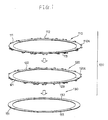
- FIG. 1 is an exploded perspective view of an annular portion of the driven pulley shown in FIG. 1
- FIG. 2 is a construction diagram of a tooth portion formed on a circumferential surface of the annular portion shown in FIG. 1
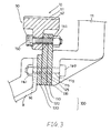
- FIG. 3 is a diagram illustrating in what manner the tooth portion of the driven pulley shown in FIG. 1 is mounted and in what manner the driven pulley is mounted with respect to an extension stage and a slip ring plate.
- the driven pulley 10 comprises an annular portion 100 and a tooth portion 90 formed along a circumferential surface of the annular portion 100, the tooth portion 90 comprising a plurality of resin teeth 92 having blades 91 formed on the side opposite to the side which is opposed to the circumferential surface of the annular portion 100.
- the annular portion 100 comprises three generally annular plates which are a first ring 110, a second ring 120 and a third ring 130.
- the first ring 110 is divided into three arcuate plates 111, 112 and 113.
- the second and third rings 120, 130 are also divided into three arcuate plates 121, 122, 123 and three arcuate plates 131, 132, 133, respectively.
- the first, second and third rings 110, 120, 130 are laminated together in such a manner that the divided positions of the arcuate plates 111, 112, 113 of the first ring 110, the divided positions of the arcuate plates 121, 122, 123 of the second ring 120, and the divided positions of the arcuate plates 131, 132, 133 of the third ring 130, are different from one another.
- the three rings thus laminated are then clamped together using rivets or the like to constitute the annular portion 100.
- bracket portions 110a and 120a for mounting the resin teeth 92 are formed on circumferential surfaces of the first and second rings 110, 120, respectively.
- the bracket portions 110a and 120a are formed so as to be aligned with each other when both rings are laminated together.
- the rings 110, 120 and 130 are each formed in a polygonal shape closely similar to a circular are so that they can be obtained using a turret punch.
- the resin teeth 92 is mounted to a circumferential surface of the annular portion 100, using bolts 150 and nuts 151 threadedly engaged with the bolts 150, the bolts 150 being inserted into holes 92a formed in the resin teeth 92 and further through U-shaped slots 120b, 110b formed in the bracket portions 120a, 110a, respectively.
- the driven pulley 10, the slip ring plate 11 and the extension stage 9 are mounted by being clamped together with bolts 160 and nuts 161 which are threaded to engage with the bolts 160, the bolts 160 each being inserted into a through hole 11a, through holes 115, 125 and 135 formed in the rings 110, 120 and 130, respectively, and a through hole 9a formed in the extension stage 9.
- the component 170 is mounted so as to straddle arcuate plates 111 and 112 adjacent to each other, and out of two sets of bolts and nuts for mounting the component 170 to the annular portion 100, one set of bolt 171 and nut 172 are used to clamping the plates 111, 121 and 131 together, while the other set of bolt 173 and nut 174 are used to clamp the plates 112,121 and 131 together.
- each ring is divided into three plates, it is desirable to change the number of divisions in accordance with the diameter of the driven pulley and the size of the material to be subjected to turret punching.
Landscapes
- Engineering & Computer Science (AREA)
- General Engineering & Computer Science (AREA)
- Health & Medical Sciences (AREA)
- Life Sciences & Earth Sciences (AREA)
- Mechanical Engineering (AREA)
- Medical Informatics (AREA)
- Optics & Photonics (AREA)
- Biomedical Technology (AREA)
- Biophysics (AREA)
- High Energy & Nuclear Physics (AREA)
- Theoretical Computer Science (AREA)
- Nuclear Medicine, Radiotherapy & Molecular Imaging (AREA)
- Pulmonology (AREA)
- Pathology (AREA)
- Radiology & Medical Imaging (AREA)
- Physics & Mathematics (AREA)
- Heart & Thoracic Surgery (AREA)
- Molecular Biology (AREA)
- Surgery (AREA)
- Animal Behavior & Ethology (AREA)
- General Health & Medical Sciences (AREA)
- Public Health (AREA)
- Veterinary Medicine (AREA)
- Apparatus For Radiation Diagnosis (AREA)
- Pulleys (AREA)
Applications Claiming Priority (3)
| Application Number | Priority Date | Filing Date | Title |
|---|---|---|---|
| JP26128697A JP3209951B2 (ja) | 1997-09-26 | 1997-09-26 | プーリ及びct装置 |
| JP26128697 | 1997-09-26 | ||
| JP261286/97 | 1997-09-26 |
Publications (3)
| Publication Number | Publication Date |
|---|---|
| EP0905416A2 true EP0905416A2 (fr) | 1999-03-31 |
| EP0905416A3 EP0905416A3 (fr) | 1999-11-03 |
| EP0905416B1 EP0905416B1 (fr) | 2003-06-25 |
Family
ID=17359707
Family Applications (1)
| Application Number | Title | Priority Date | Filing Date |
|---|---|---|---|
| EP98307834A Expired - Lifetime EP0905416B1 (fr) | 1997-09-26 | 1998-09-25 | Poulie et tomographe à balayage assisté par ordinateur pourvu de cette poulie |
Country Status (7)
| Country | Link |
|---|---|
| US (1) | US6349127B1 (fr) |
| EP (1) | EP0905416B1 (fr) |
| JP (1) | JP3209951B2 (fr) |
| KR (1) | KR100709022B1 (fr) |
| CN (1) | CN1161076C (fr) |
| DE (1) | DE69815779T2 (fr) |
| TW (1) | TW411840U (fr) |
Families Citing this family (6)
| Publication number | Priority date | Publication date | Assignee | Title |
|---|---|---|---|---|
| JP3209951B2 (ja) * | 1997-09-26 | 2001-09-17 | ジーイー横河メディカルシステム株式会社 | プーリ及びct装置 |
| WO2000033058A2 (fr) * | 1998-11-30 | 2000-06-08 | Invision Technologies, Inc. | Systeme d'inspection non intrusif |
| JP3854244B2 (ja) * | 2003-05-16 | 2006-12-06 | 株式会社東芝 | 永久磁石形モータ及びx線コンピュータ断層撮影装置 |
| JP2006280919A (ja) * | 2005-03-07 | 2006-10-19 | Toshiba Corp | X線ct装置 |
| US20130008272A1 (en) * | 2011-07-07 | 2013-01-10 | Salov Dmitriy A | Gear rim with elastic cassettes |
| KR101673951B1 (ko) | 2014-08-01 | 2016-11-09 | 주식회사 부강테크 | 터보 블로워 분리형 임펠러 |
Family Cites Families (10)
| Publication number | Priority date | Publication date | Assignee | Title |
|---|---|---|---|---|
| US3225616A (en) | 1964-05-18 | 1965-12-28 | Scott & Williams Inc | Gear construction |
| JPS5074844U (fr) * | 1973-11-14 | 1975-06-30 | ||
| JPS5079859A (fr) * | 1973-11-19 | 1975-06-28 | ||
| JPS5079859U (fr) * | 1973-11-26 | 1975-07-10 | ||
| US3891868A (en) * | 1974-05-03 | 1975-06-24 | Science Res Council | Electrically-conducting materials |
| JPS50157757A (fr) * | 1974-06-13 | 1975-12-19 | ||
| US4115695A (en) | 1977-02-25 | 1978-09-19 | General Electric Company | Gantry for computed tomography |
| JPH0824249A (ja) | 1994-07-15 | 1996-01-30 | Ge Yokogawa Medical Syst Ltd | プーリ及びプーリの組付け方法 |
| JP3209951B2 (ja) * | 1997-09-26 | 2001-09-17 | ジーイー横河メディカルシステム株式会社 | プーリ及びct装置 |
| US5982844A (en) * | 1997-10-10 | 1999-11-09 | Analogic Corporation | Computed tomography scanner drive system and bearing |
-
1997
- 1997-09-26 JP JP26128697A patent/JP3209951B2/ja not_active Expired - Fee Related
-
1998
- 1998-09-19 US US09/157,355 patent/US6349127B1/en not_active Expired - Lifetime
- 1998-09-24 TW TW089204560U patent/TW411840U/zh not_active IP Right Cessation
- 1998-09-25 DE DE69815779T patent/DE69815779T2/de not_active Expired - Fee Related
- 1998-09-25 KR KR1019980039837A patent/KR100709022B1/ko not_active Expired - Fee Related
- 1998-09-25 EP EP98307834A patent/EP0905416B1/fr not_active Expired - Lifetime
- 1998-09-26 CN CNB981205984A patent/CN1161076C/zh not_active Expired - Fee Related
Non-Patent Citations (1)
| Title |
|---|
| None |
Also Published As
| Publication number | Publication date |
|---|---|
| JPH1199149A (ja) | 1999-04-13 |
| EP0905416B1 (fr) | 2003-06-25 |
| US6349127B1 (en) | 2002-02-19 |
| TW411840U (en) | 2000-11-11 |
| EP0905416A3 (fr) | 1999-11-03 |
| CN1161076C (zh) | 2004-08-11 |
| KR100709022B1 (ko) | 2007-07-09 |
| CN1212860A (zh) | 1999-04-07 |
| KR19990030121A (ko) | 1999-04-26 |
| JP3209951B2 (ja) | 2001-09-17 |
| DE69815779T2 (de) | 2004-04-29 |
| DE69815779D1 (de) | 2003-07-31 |
Similar Documents
| Publication | Publication Date | Title |
|---|---|---|
| US5256926A (en) | Alternating-current generator with stator center lamination and method for producing the center lamination | |
| EP0905416B1 (fr) | Poulie et tomographe à balayage assisté par ordinateur pourvu de cette poulie | |
| CN109391056B (zh) | 轴向间隙电动机及转子的制造方法 | |
| JP2019060739A (ja) | 可動側部材 | |
| CA2043918A1 (fr) | Entrainement sans engrenage, pour appareils elevateurs | |
| CA2165361A1 (fr) | Disque de sciage | |
| US1740087A (en) | Sheave structure | |
| US11034562B2 (en) | Modular powered hoist with integrated lift/guide assembly | |
| US6367300B1 (en) | Sprocket with thin body and grooved teeth | |
| DE102015102777A1 (de) | Lichtmaschine umfassend einen Statorkern mit Nutauskleidungen | |
| CA2377606C (fr) | Roue d'avancement | |
| US4114473A (en) | Guard for belt pulley | |
| CN107407395B (zh) | 绳轮 | |
| US20050279611A1 (en) | Actuating device for a moving sidewalk | |
| CN213185673U (zh) | 永磁变频一体机 | |
| CA1078811A (fr) | Moufle fixe et mode de fabrication de poulies | |
| DE50004719D1 (de) | Antrieb für Zylinder einer Druckmaschine | |
| KR101919205B1 (ko) | 발전기의 엔드 실드용 지그 | |
| JP5805330B2 (ja) | 回転電機、及びその製造方法 | |
| JP3497077B2 (ja) | ワイヤソーのワイヤガイドローラ | |
| FI68712B (fi) | Anordning foer fastsaettning av kraftoeverfoeringshjulet | |
| JP3945845B2 (ja) | 電動式鋸用鋸刃 | |
| CN111245133A (zh) | 永磁变频一体机 | |
| JP3005950U (ja) | 魚切断装置 | |
| JPS6256378B2 (fr) |
Legal Events
| Date | Code | Title | Description |
|---|---|---|---|
| PUAI | Public reference made under article 153(3) epc to a published international application that has entered the european phase |
Free format text: ORIGINAL CODE: 0009012 |
|
| AK | Designated contracting states |
Kind code of ref document: A2 Designated state(s): DE ES FR GB IT NL |
|
| AX | Request for extension of the european patent |
Free format text: AL;LT;LV;MK;RO;SI |
|
| PUAL | Search report despatched |
Free format text: ORIGINAL CODE: 0009013 |
|
| AK | Designated contracting states |
Kind code of ref document: A3 Designated state(s): AT BE CH CY DE DK ES FI FR GB GR IE IT LI LU MC NL PT SE |
|
| AX | Request for extension of the european patent |
Free format text: AL;LT;LV;MK;RO;SI |
|
| 17P | Request for examination filed |
Effective date: 20000503 |
|
| AKX | Designation fees paid |
Free format text: DE ES FR GB IT NL |
|
| 17Q | First examination report despatched |
Effective date: 20020325 |
|
| GRAH | Despatch of communication of intention to grant a patent |
Free format text: ORIGINAL CODE: EPIDOS IGRA |
|
| GRAH | Despatch of communication of intention to grant a patent |
Free format text: ORIGINAL CODE: EPIDOS IGRA |
|
| GRAA | (expected) grant |
Free format text: ORIGINAL CODE: 0009210 |
|
| AK | Designated contracting states |
Designated state(s): DE ES FR GB IT NL |
|
| PG25 | Lapsed in a contracting state [announced via postgrant information from national office to epo] |
Ref country code: NL Free format text: LAPSE BECAUSE OF FAILURE TO SUBMIT A TRANSLATION OF THE DESCRIPTION OR TO PAY THE FEE WITHIN THE PRESCRIBED TIME-LIMIT Effective date: 20030625 Ref country code: IT Free format text: LAPSE BECAUSE OF FAILURE TO SUBMIT A TRANSLATION OF THE DESCRIPTION OR TO PAY THE FEE WITHIN THE PRESCRIBED TIME-LIMIT;WARNING: LAPSES OF ITALIAN PATENTS WITH EFFECTIVE DATE BEFORE 2007 MAY HAVE OCCURRED AT ANY TIME BEFORE 2007. THE CORRECT EFFECTIVE DATE MAY BE DIFFERENT FROM THE ONE RECORDED. Effective date: 20030625 |
|
| REG | Reference to a national code |
Ref country code: GB Ref legal event code: FG4D |
|
| REF | Corresponds to: |
Ref document number: 69815779 Country of ref document: DE Date of ref document: 20030731 Kind code of ref document: P |
|
| PGFP | Annual fee paid to national office [announced via postgrant information from national office to epo] |
Ref country code: NL Payment date: 20030909 Year of fee payment: 6 |
|
| NLV1 | Nl: lapsed or annulled due to failure to fulfill the requirements of art. 29p and 29m of the patents act | ||
| PG25 | Lapsed in a contracting state [announced via postgrant information from national office to epo] |
Ref country code: ES Free format text: LAPSE BECAUSE OF FAILURE TO SUBMIT A TRANSLATION OF THE DESCRIPTION OR TO PAY THE FEE WITHIN THE PRESCRIBED TIME-LIMIT Effective date: 20031222 |
|
| PLBE | No opposition filed within time limit |
Free format text: ORIGINAL CODE: 0009261 |
|
| STAA | Information on the status of an ep patent application or granted ep patent |
Free format text: STATUS: NO OPPOSITION FILED WITHIN TIME LIMIT |
|
| ET | Fr: translation filed | ||
| 26N | No opposition filed |
Effective date: 20040326 |
|
| PGFP | Annual fee paid to national office [announced via postgrant information from national office to epo] |
Ref country code: FR Payment date: 20060918 Year of fee payment: 9 |
|
| PGFP | Annual fee paid to national office [announced via postgrant information from national office to epo] |
Ref country code: GB Payment date: 20060925 Year of fee payment: 9 |
|
| GBPC | Gb: european patent ceased through non-payment of renewal fee |
Effective date: 20070925 |
|
| REG | Reference to a national code |
Ref country code: FR Ref legal event code: ST Effective date: 20080531 |
|
| PG25 | Lapsed in a contracting state [announced via postgrant information from national office to epo] |
Ref country code: FR Free format text: LAPSE BECAUSE OF NON-PAYMENT OF DUE FEES Effective date: 20071001 |
|
| PG25 | Lapsed in a contracting state [announced via postgrant information from national office to epo] |
Ref country code: GB Free format text: LAPSE BECAUSE OF NON-PAYMENT OF DUE FEES Effective date: 20070925 |
|
| PGFP | Annual fee paid to national office [announced via postgrant information from national office to epo] |
Ref country code: DE Payment date: 20081031 Year of fee payment: 11 |
|
| PG25 | Lapsed in a contracting state [announced via postgrant information from national office to epo] |
Ref country code: DE Free format text: LAPSE BECAUSE OF NON-PAYMENT OF DUE FEES Effective date: 20100401 |