EP0905422A1 - Vanne a papillon en plastique - Google Patents
Vanne a papillon en plastique Download PDFInfo
- Publication number
- EP0905422A1 EP0905422A1 EP98912723A EP98912723A EP0905422A1 EP 0905422 A1 EP0905422 A1 EP 0905422A1 EP 98912723 A EP98912723 A EP 98912723A EP 98912723 A EP98912723 A EP 98912723A EP 0905422 A1 EP0905422 A1 EP 0905422A1
- Authority
- EP
- European Patent Office
- Prior art keywords
- seat
- pressure foot
- butterfly valve
- projections
- seat pressure
- Prior art date
- Legal status (The legal status is an assumption and is not a legal conclusion. Google has not performed a legal analysis and makes no representation as to the accuracy of the status listed.)
- Withdrawn
Links
Images


Classifications
-
- F—MECHANICAL ENGINEERING; LIGHTING; HEATING; WEAPONS; BLASTING
- F16—ENGINEERING ELEMENTS AND UNITS; GENERAL MEASURES FOR PRODUCING AND MAINTAINING EFFECTIVE FUNCTIONING OF MACHINES OR INSTALLATIONS; THERMAL INSULATION IN GENERAL
- F16K—VALVES; TAPS; COCKS; ACTUATING-FLOATS; DEVICES FOR VENTING OR AERATING
- F16K1/00—Lift valves or globe valves, i.e. cut-off apparatus with closure members having at least a component of their opening and closing motion perpendicular to the closing faces
- F16K1/16—Lift valves or globe valves, i.e. cut-off apparatus with closure members having at least a component of their opening and closing motion perpendicular to the closing faces with pivoted closure-members
- F16K1/18—Lift valves or globe valves, i.e. cut-off apparatus with closure members having at least a component of their opening and closing motion perpendicular to the closing faces with pivoted closure-members with pivoted discs or flaps
- F16K1/22—Lift valves or globe valves, i.e. cut-off apparatus with closure members having at least a component of their opening and closing motion perpendicular to the closing faces with pivoted closure-members with pivoted discs or flaps with axis of rotation crossing the valve member, e.g. butterfly valves
- F16K1/226—Shaping or arrangements of the sealing
- F16K1/2263—Shaping or arrangements of the sealing the sealing being arranged on the valve seat
Definitions
- the present invention relates to a plastic butterfly valve preferably used in a piping line for a chemical plant, a city water supply or the like and more particularly, to a plastic butterfly valve in which the seat can be easily mounted and demounted in a short time.
- the body in the former butterfly valve, the body must be tapped with tapped holes for bolts to fix the seat pressure foot, thus not only does the cost increase as a result of an increase of working processes, but also a long time is required for fastening the bolts, thus the efficiency of the assembling work is deteriorated.
- the present invention has been conceived in view of the problems of the conventional technique as stated above and the purpose of this invention is to provide a plastic butterfly valve that does not require the tapped holes in the body and the seat pressure foot, it is not possible to damage the engaging regions during disassembly, and the mounting and the demounting the seat can be easily and rapidly carried out.
- the present invention has been conceived in view of the above conventional technique, and relates to an eccentric type plastic butterfly valve characterized in that a seat pressure foot is detachably fitted in the side portion of a body by insertion/rotation means (that is, by a bayonet manner) so that the seat can be easily mounted and demounted in a short time.
- a fitting arrangement by the insertion/rotation means (the bayonet manner) in the present invention consist in the following. First, the construction of the seat pressure foot will be explained.
- the seat pressure foot is formed with a plurality of arcuate projections at the outer peripheral end surface and is provided with a step portion fitting on and holding the seat at the inner peripheral side of the seat pressure foot.
- the cutout step portion is diametrically provided with arcuate cutout portions having enlarged diameters in which the arcuate projections are fitted, in positions corresponding to the circular arc projections of the seat pressure foot, and is provided at the interior sides of the cutout portions with an annular engaging groove in which the arcuate projections of the seat pressure foot, the foot having been inserted, are circumferentially guided.
- the seat is fitted in the step portion of the seat pressure foot to fit the arcuate projections provided on the outer peripheral end surface of the seat pressure foot into the arcuate cutout portions provided on the side portion of the body. Then, the seat pressure foot is pushed in until the interior side of the seat fitted in the seat pressure foot comes in contact with the interior bottom portion of the arcuate cutout step portions of the body while the seat pressure foot is circumferentially rotated to guide the arcuate projections in the annular engaging groove of the body.
- This fitting manner is referred to as insertion/rotation means (bayonet manner) in the present invention.
- At least two of the arcuate projections must be provided on the outer peripheral end surface of the seat pressure foot, and the number of the arcuate projections may be suitably selected depending on the size of the diameter of the passage of the butterfly valve. Also, the width of the projections (the length in the axial direction of the seat pressure foot) must be smaller than the thickness of the seat pressure foot, and may be preferably set to 40 to 50% of the thickness of the seat pressure foot.
- the forming process of the projections is desirably an integral molding, although any of an integral molding, a fitting manner, a bonding or the like may be used.
- the material used in the butterfly valve in the present invention may be any available plastic, and generally hard vinyl chloride resin, polypropylene, and fluorocarbon resin such as PVDF are preferred.
- Fig. 1 is a longitudinal section showing the closed state of an eccentric type butterfly valve made of vinyl chloride resin, according to the present invention.
- reference numeral 1 is a hollow cylindrical body, in the interior of which a flow passage is formed and a valve disk 4 is eccentrically and rotatably supported by a stem 17.
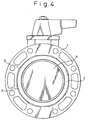
- Reference numeral 2 is a seat pressure foot on the outer peripheral end surface of which eight arcuate L-shaped projections 9 (Fig. 3) are provided, the projections being circumferentially arranged at an even spacing and integrally molded with the seat pressure foot, as shown in Fig. 4. Also, on the inner peripheral side of the seat pressure foot 2 is provided a step portion 10 for holding a seat 3 by fitting over the seat 3 as shown in Fig. 2.
- the depth in the axial direction of the step portion 10 is slightly smaller than the width of the seat 3 in the axial direction. That is, the depth of the step portion 10 is set up smaller by an interference in the axial direction of the seat 3.
- an annular small projection 11 of a trapezoidal cross-section for fixing the seat 3.
- the inner diameter of the seat pressure foot 2 is not specifically limited, making the contact area with the seat 3 as large as possible, in other words, setting the inner diameter of the seat pressure foot smaller than the inner diameter of the flow passage of the body 1 is more effective for safely holding the seat 3.
- Reference numeral 7 is a cutout step portion of a circular hole arranged on one side of the body 1, which has the same diameter as the outer diameter of the seat pressure foot 2 and in which the seat pressure foot 2 and the seat 3 are fitted.
- Reference numeral 5 is an arcuate cutout portion diametrically arranged on the cutout step portion 7 of the body in the position corresponding to the L-shaped projection 9 of the seat pressure foot 2, as shown in Figs. 3 and 4.
- an annular small projection 8 in the position opposite to the small projection 11, similarly to the seat pressure foot 2.
- Reference numeral 3 is a seat of a shell-like cross-section arranged perpendicularly to the axis of the flow passage of the body 1 and the inner peripheral surface of which is formed in an arcuate shape.
- the seat is pinched by the seat pressure foot 2 and the body 1 and is fixed on the interior of the body 1, that is, the bottom of the cutout step portion 7 of the body 1 by the seat pressure foot 2 (refer to Figs. 1 and 2).
- annular grooves 13 and 14 with which the small projections 8 and 11 are engaged are arranged on both outer peripheral sides of the seat 3.
- Fig. 1 annular grooves 13 and 14 with which the small projections 8 and 11 are engaged are arranged on both outer peripheral sides of the seat 3.
- the arcuate inner surface of the seat 3 projects toward the flow passage side of the body 1, thus, when the valve is completely closed, the periphery of the eccentrically arranged valve disk 4 and the inner surface of the seat 3 abut on each other so that the sealing can be maintained.
- the seat 3 is fitted in the step portion 10 of the seat pressure foot 2, then the L-shaped projections 9 of the seat pressure foot 3 are fitted in the arcuate cutout portions 5 arranged on the cutout step portion 7 of the body 1 and are pushed in until the seat 3 comes in contact with the bottom of the cutout step portion 7.
- the seat pressure foot 2 is circumferentially rotated to guide the parallel portions 15 of the L-shaped projections 9 in the engaging groove 6, and is further rotated until the vertical portions 16 of the L-shaped projections 9 come in contact with the walls of the cutout portions 5 of the body 1. (Refer to Figs. 3 and 4. In Fig. 3, the state where the seat pressure foot 2 is rotated clockwise so that the L-shaped projection 9 is moved from the dotted line position to the position shown in Fig. 3 is shown.)
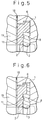
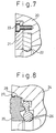
- Fig. 5 is a longitudinal section of the essential parts showing the state of the seat pressure foot 2 and the seat 3 when the butterfly valve according to the embodiment is mounted.
- the seat pressure foot 2 is pressed by a flange 19 etc. via a packing 18 so that the seat pressure foot 2 contacts with the bottom surface of the cutout step portion 7 of the body 1 and the seat 3 is strongly fixed due to the seat 3 being compressed by the moved amount of the seat, that is the interference of the seat 3.
- Fig. 6 is a longitudinal section of the essential parts showing another embodiment of the seat 3.
- the seat 3 according to the above first embodiment is further provided with a flange-like seal portion on the outer peripheral portion of the seat 3 so that the sealing performance between the body 1 and the seat pressure foot 2 is improved.
- the plastic butterfly valve according to the present invention allows the seat pressure foot to be detachably fitted in the body by the insertion/rotation means (bayonet manner) to fix the seat, providing tapped holes for screwing the bolts is not required, there is no danger that the engaging portions are damaged when disassembled, the mounting and demounting of the seat can be rapidly carried out without using a special tool, and the costs for production and maintenance can be reduced. Also, since the butterfly valve is made of plastic, and there are obtained the effects that the butterfly valve is light and is superior in corrosion resistance.
- the present invention is preferably applicable to chemical plants and piping lines in a city water supply.
Landscapes
- Engineering & Computer Science (AREA)
- General Engineering & Computer Science (AREA)
- Mechanical Engineering (AREA)
- Lift Valve (AREA)
Applications Claiming Priority (3)
| Application Number | Priority Date | Filing Date | Title |
|---|---|---|---|
| JP9095899A JPH10288262A (ja) | 1997-04-14 | 1997-04-14 | プラスチック製バタフライ弁 |
| JP95899/97 | 1997-04-14 | ||
| PCT/JP1998/001619 WO1998046917A1 (fr) | 1997-04-14 | 1998-04-08 | Vanne a papillon en plastique |
Publications (2)
| Publication Number | Publication Date |
|---|---|
| EP0905422A1 true EP0905422A1 (fr) | 1999-03-31 |
| EP0905422A4 EP0905422A4 (fr) | 2004-05-19 |
Family
ID=14150156
Family Applications (1)
| Application Number | Title | Priority Date | Filing Date |
|---|---|---|---|
| EP98912723A Withdrawn EP0905422A4 (fr) | 1997-04-14 | 1998-04-08 | Vanne a papillon en plastique |
Country Status (5)
| Country | Link |
|---|---|
| US (1) | US6189860B1 (fr) |
| EP (1) | EP0905422A4 (fr) |
| JP (1) | JPH10288262A (fr) |
| CA (1) | CA2255718C (fr) |
| WO (1) | WO1998046917A1 (fr) |
Cited By (1)
| Publication number | Priority date | Publication date | Assignee | Title |
|---|---|---|---|---|
| EP1574763A1 (fr) * | 2004-03-11 | 2005-09-14 | Ksb S.A.S | Robinet à arbre sec et son procédé de montage |
Families Citing this family (13)
| Publication number | Priority date | Publication date | Assignee | Title |
|---|---|---|---|---|
| US20030209683A1 (en) * | 2002-05-08 | 2003-11-13 | Tsai Chi-Lung | Handle-type butterfly valve |
| US7172614B2 (en) * | 2002-06-27 | 2007-02-06 | Advanced Cardiovascular Systems, Inc. | Support structures for embolic filtering devices |
| DE20213442U1 (de) | 2002-08-06 | 2003-01-02 | Xomox International GmbH & Co, 88131 Lindau | Armatur |
| US8430113B2 (en) * | 2007-04-26 | 2013-04-30 | Asahi Organic Chemicals Industry Co., Ltd. | Method of manufacturing valve, and valve produced by the method |
| US8348236B2 (en) * | 2007-10-31 | 2013-01-08 | Saint-Gobain Performance Plastics Corporation | Butterfly valve with a rigid seal |
| FR2922984B1 (fr) * | 2007-10-31 | 2013-09-27 | Saint Gobain Performance Plast | Vanne ayant un joint rigide |
| FR2922988B1 (fr) | 2007-10-31 | 2012-10-12 | Saint Gobain Performance Plast | Assemblages de tuyaux |
| KR101096525B1 (ko) * | 2011-04-26 | 2011-12-20 | 서광공업 주식회사 | 저온 및 고온에서 실링성능이 유지되는 버터플라이 밸브 |
| US9989154B2 (en) | 2013-07-30 | 2018-06-05 | Hayward Industries, Inc. | Butterfly valve handle |
| US9695947B2 (en) | 2013-07-30 | 2017-07-04 | Hayward Industries, Inc. | Handle insert for valve |
| NZ741352A (en) * | 2015-11-23 | 2019-10-25 | Victaulic Co Of America | Valve and valve coupling with reverse tapered shafts |
| JP7500249B2 (ja) * | 2020-03-31 | 2024-06-17 | 株式会社キッツ | 二重偏心型バタフライ弁とその製造方法 |
| EP4311960A1 (fr) * | 2022-07-27 | 2024-01-31 | UTC Aerospace Systems Wroclaw Sp. z o.o. | Vannes papillon |
Family Cites Families (12)
| Publication number | Priority date | Publication date | Assignee | Title |
|---|---|---|---|---|
| GB936591A (en) * | 1959-02-02 | 1963-09-11 | Apv Co Ltd | A new or improved pipe closure |
| GB888541A (en) * | 1959-08-25 | 1962-01-31 | Kac Ltd | Improvements in self-sealing releasable couplings for use in fluid pressure lines |
| CH601704A5 (fr) | 1974-12-05 | 1978-07-14 | Pont A Mousson | |
| US4231546A (en) * | 1978-12-22 | 1980-11-04 | Fisher Controls Company, Inc. | High-temperature bidirectional metal seal |
| US4289296A (en) * | 1979-03-23 | 1981-09-15 | Xomox Corporation | Bidirectional axially pliant pressure assisted seat for a valve |
| JPS5857566A (ja) * | 1981-10-02 | 1983-04-05 | Asahi Organic Chem Ind Co Ltd | バタフライバルブ |
| US4813650A (en) * | 1987-07-08 | 1989-03-21 | Xomox Corporation | Valve seat retainer |
| JPH0410168A (ja) | 1990-04-27 | 1992-01-14 | Mitsubishi Electric Corp | プリント基板の設計データチェック方式 |
| JP2509859Y2 (ja) * | 1990-05-17 | 1996-09-04 | 株式会社巴技術研究所 | バタフライ弁のシ―トリング固定装置 |
| JP2904302B2 (ja) | 1990-05-29 | 1999-06-14 | キヤノン株式会社 | 画像処理装置 |
| JPH0729346Y2 (ja) * | 1990-07-13 | 1995-07-05 | 高砂熱学工業株式会社 | バタフライ弁 |
| JP3722615B2 (ja) * | 1998-03-18 | 2005-11-30 | 旭有機材工業株式会社 | プラスチック製バタフライ弁 |
-
1997
- 1997-04-14 JP JP9095899A patent/JPH10288262A/ja active Pending
-
1998
- 1998-04-08 US US09/194,740 patent/US6189860B1/en not_active Expired - Fee Related
- 1998-04-08 EP EP98912723A patent/EP0905422A4/fr not_active Withdrawn
- 1998-04-08 CA CA002255718A patent/CA2255718C/fr not_active Expired - Fee Related
- 1998-04-08 WO PCT/JP1998/001619 patent/WO1998046917A1/fr not_active Ceased
Cited By (2)
| Publication number | Priority date | Publication date | Assignee | Title |
|---|---|---|---|---|
| EP1574763A1 (fr) * | 2004-03-11 | 2005-09-14 | Ksb S.A.S | Robinet à arbre sec et son procédé de montage |
| FR2867544A1 (fr) * | 2004-03-11 | 2005-09-16 | Ksb Sas | Robinet a arbre sec et son procede de montage |
Also Published As
| Publication number | Publication date |
|---|---|
| CA2255718A1 (fr) | 1998-10-22 |
| EP0905422A4 (fr) | 2004-05-19 |
| WO1998046917A1 (fr) | 1998-10-22 |
| CA2255718C (fr) | 2003-02-18 |
| US6189860B1 (en) | 2001-02-20 |
| JPH10288262A (ja) | 1998-10-27 |
Similar Documents
| Publication | Publication Date | Title |
|---|---|---|
| CA2255718C (fr) | Vanne a papillon en plastique | |
| JP4719209B2 (ja) | 流体配管系統の流路遮断方法 | |
| JP2005180503A (ja) | 管接続構造 | |
| JPWO2004076894A1 (ja) | リップ型シール | |
| US20120222753A1 (en) | Device for work implementation without stopping flow, and method for work implementation without stopping flow | |
| US4676479A (en) | Flanged valve | |
| KR100351379B1 (ko) | 볼트체결형커플링 | |
| JP3722612B2 (ja) | プラスチック製バタフライ弁 | |
| JP5528046B2 (ja) | ボールバルブ | |
| JP2001146996A (ja) | 流体輸送管用弁装着装置 | |
| KR200224585Y1 (ko) | 버터플라이 밸브 | |
| KR20010077806A (ko) | 볼 밸브 | |
| EP0010357B1 (fr) | Vanne à papillon | |
| JP7337702B2 (ja) | バタフライバルブの配管用調芯機構 | |
| JPWO2004092625A1 (ja) | バタフライ弁 | |
| KR101565545B1 (ko) | 스테인리스 스틸 관로를 갖는 버터플라이 밸브 및 그 제조방법 | |
| US20200355290A1 (en) | Butterfly valve | |
| KR102459704B1 (ko) | 디스크 변위식 버터플라이밸브 | |
| CN220134766U (zh) | 阀芯组件及截止阀 | |
| JP2006183730A (ja) | 流体用機器の取り付け構造 | |
| JP2007192387A (ja) | ホースバンド | |
| KR200311887Y1 (ko) | 요철형 고무시트 버터플라이밸브 | |
| JP2006207759A (ja) | バタフライバルブ用弁体およびそれを用いたバタフライバルブならびにバタフライバルブ用弁体の製造方法 | |
| JP3893219B2 (ja) | 吸気弁用接続具 | |
| JP2006177395A (ja) | ボールバルブ |
Legal Events
| Date | Code | Title | Description |
|---|---|---|---|
| PUAI | Public reference made under article 153(3) epc to a published international application that has entered the european phase |
Free format text: ORIGINAL CODE: 0009012 |
|
| 17P | Request for examination filed |
Effective date: 19981113 |
|
| AK | Designated contracting states |
Kind code of ref document: A1 Designated state(s): AT CH DE ES FR GB IT LI SE |
|
| STAA | Information on the status of an ep patent application or granted ep patent |
Free format text: STATUS: THE APPLICATION IS DEEMED TO BE WITHDRAWN |
|
| 18D | Application deemed to be withdrawn |
Effective date: 20031104 |
|
| A4 | Supplementary search report drawn up and despatched |
Effective date: 20040402 |