EP0905433B1 - Procédé et dispositif pour l'installation, le positionnement et la fixation de pièces dans des cavités avec une section transversale divergente - Google Patents
Procédé et dispositif pour l'installation, le positionnement et la fixation de pièces dans des cavités avec une section transversale divergente Download PDFInfo
- Publication number
- EP0905433B1 EP0905433B1 EP98250326A EP98250326A EP0905433B1 EP 0905433 B1 EP0905433 B1 EP 0905433B1 EP 98250326 A EP98250326 A EP 98250326A EP 98250326 A EP98250326 A EP 98250326A EP 0905433 B1 EP0905433 B1 EP 0905433B1
- Authority
- EP
- European Patent Office
- Prior art keywords
- fastening elements
- cavity
- elements
- guide
- fastening
- Prior art date
- Legal status (The legal status is an assumption and is not a legal conclusion. Google has not performed a legal analysis and makes no representation as to the accuracy of the status listed.)
- Expired - Lifetime
Links
- 238000000034 method Methods 0.000 title claims abstract description 35
- 239000000853 adhesive Substances 0.000 claims description 12
- 239000000463 material Substances 0.000 claims description 11
- 230000001070 adhesive effect Effects 0.000 claims description 10
- 238000005520 cutting process Methods 0.000 claims description 5
- 239000011248 coating agent Substances 0.000 claims description 4
- 238000000576 coating method Methods 0.000 claims description 4
- 238000003825 pressing Methods 0.000 claims description 4
- 238000012544 monitoring process Methods 0.000 claims description 2
- 238000012856 packing Methods 0.000 claims description 2
- 239000012858 resilient material Substances 0.000 claims description 2
- 230000008961 swelling Effects 0.000 claims description 2
- 238000004026 adhesive bonding Methods 0.000 claims 1
- 238000005266 casting Methods 0.000 claims 1
- 238000013016 damping Methods 0.000 claims 1
- 238000006073 displacement reaction Methods 0.000 claims 1
- 235000014676 Phragmites communis Nutrition 0.000 abstract 6
- 238000007373 indentation Methods 0.000 description 12
- 238000005553 drilling Methods 0.000 description 4
- 238000005516 engineering process Methods 0.000 description 4
- 238000009434 installation Methods 0.000 description 4
- 230000001681 protective effect Effects 0.000 description 4
- 230000000694 effects Effects 0.000 description 3
- 150000001875 compounds Chemical class 0.000 description 2
- 239000000109 continuous material Substances 0.000 description 2
- 238000004382 potting Methods 0.000 description 2
- 239000002390 adhesive tape Substances 0.000 description 1
- 230000015572 biosynthetic process Effects 0.000 description 1
- 238000004891 communication Methods 0.000 description 1
- 238000010276 construction Methods 0.000 description 1
- 238000011109 contamination Methods 0.000 description 1
- 229910003460 diamond Inorganic materials 0.000 description 1
- 239000010432 diamond Substances 0.000 description 1
- 230000008030 elimination Effects 0.000 description 1
- 238000003379 elimination reaction Methods 0.000 description 1
- 239000003673 groundwater Substances 0.000 description 1
- 238000003780 insertion Methods 0.000 description 1
- 230000037431 insertion Effects 0.000 description 1
- 239000002184 metal Substances 0.000 description 1
- 230000036316 preload Effects 0.000 description 1
- 239000007787 solid Substances 0.000 description 1
- 239000011343 solid material Substances 0.000 description 1
- 238000005507 spraying Methods 0.000 description 1
- 238000012549 training Methods 0.000 description 1
- XLYOFNOQVPJJNP-UHFFFAOYSA-N water Substances O XLYOFNOQVPJJNP-UHFFFAOYSA-N 0.000 description 1
Images


Classifications
-
- F—MECHANICAL ENGINEERING; LIGHTING; HEATING; WEAPONS; BLASTING
- F16—ENGINEERING ELEMENTS AND UNITS; GENERAL MEASURES FOR PRODUCING AND MAINTAINING EFFECTIVE FUNCTIONING OF MACHINES OR INSTALLATIONS; THERMAL INSULATION IN GENERAL
- F16L—PIPES; JOINTS OR FITTINGS FOR PIPES; SUPPORTS FOR PIPES, CABLES OR PROTECTIVE TUBING; MEANS FOR THERMAL INSULATION IN GENERAL
- F16L55/00—Devices or appurtenances for use in, or in connection with, pipes or pipe systems
- F16L55/16—Devices for covering leaks in pipes or hoses, e.g. hose-menders
- F16L55/162—Devices for covering leaks in pipes or hoses, e.g. hose-menders from inside the pipe
- F16L55/165—Devices for covering leaks in pipes or hoses, e.g. hose-menders from inside the pipe a pipe or flexible liner being inserted in the damaged section
- F16L55/1655—Devices for covering leaks in pipes or hoses, e.g. hose-menders from inside the pipe a pipe or flexible liner being inserted in the damaged section a pipe being formed inside the old pipe by winding strip-material
-
- G—PHYSICS
- G02—OPTICS
- G02B—OPTICAL ELEMENTS, SYSTEMS OR APPARATUS
- G02B6/00—Light guides; Structural details of arrangements comprising light guides and other optical elements, e.g. couplings
- G02B6/44—Mechanical structures for providing tensile strength and external protection for fibres, e.g. optical transmission cables
- G02B6/4439—Auxiliary devices
- G02B6/4459—Ducts; Conduits; Hollow tubes for air blown fibres
-
- G—PHYSICS
- G02—OPTICS
- G02B—OPTICAL ELEMENTS, SYSTEMS OR APPARATUS
- G02B6/00—Light guides; Structural details of arrangements comprising light guides and other optical elements, e.g. couplings
- G02B6/46—Processes or apparatus adapted for installing or repairing optical fibres or optical cables
- G02B6/48—Overhead installation
-
- G—PHYSICS
- G02—OPTICS
- G02B—OPTICAL ELEMENTS, SYSTEMS OR APPARATUS
- G02B6/00—Light guides; Structural details of arrangements comprising light guides and other optical elements, e.g. couplings
- G02B6/46—Processes or apparatus adapted for installing or repairing optical fibres or optical cables
- G02B6/50—Underground or underwater installation; Installation through tubing, conduits or ducts
- G02B6/502—Installation methods in fluid conducts, e.g. pipelines
-
- G—PHYSICS
- G02—OPTICS
- G02B—OPTICAL ELEMENTS, SYSTEMS OR APPARATUS
- G02B6/00—Light guides; Structural details of arrangements comprising light guides and other optical elements, e.g. couplings
- G02B6/46—Processes or apparatus adapted for installing or repairing optical fibres or optical cables
- G02B6/50—Underground or underwater installation; Installation through tubing, conduits or ducts
- G02B6/508—Fixation devices in ducts for drawing cables
-
- H—ELECTRICITY
- H02—GENERATION; CONVERSION OR DISTRIBUTION OF ELECTRIC POWER
- H02G—INSTALLATION OF ELECTRIC CABLES OR LINES, OR OF COMBINED OPTICAL AND ELECTRIC CABLES OR LINES
- H02G1/00—Methods or apparatus specially adapted for installing, maintaining, repairing or dismantling electric cables or lines
- H02G1/06—Methods or apparatus specially adapted for installing, maintaining, repairing or dismantling electric cables or lines for laying cables, e.g. laying apparatus on vehicle
- H02G1/08—Methods or apparatus specially adapted for installing, maintaining, repairing or dismantling electric cables or lines for laying cables, e.g. laying apparatus on vehicle through tubing or conduit, e.g. rod or draw wire for pushing or pulling
- H02G1/088—Methods or apparatus specially adapted for installing, maintaining, repairing or dismantling electric cables or lines for laying cables, e.g. laying apparatus on vehicle through tubing or conduit, e.g. rod or draw wire for pushing or pulling using pulling devices movable inside conduits
Definitions
- the invention relates to a method for introducing, positioning and fastening Components, in particular pipes, cables, rods or wires in cavities different cross-sections, for example in drainage channels in which the components are already in place or inserted using a robot and one Device for performing the method.
- the supply and disposal companies worldwide have a multitude of drainage channels of different dimensions and different materials in all supply areas. These are used to drain dirty, rain and mixed water.
- the routing networks that are widespread in telecommunications have so far mainly been placed in protective pipes in the public street. This requires the installation of these protective tubes in the ground with the resulting high costs and the negative impact on the environment and traffic. Due to the increasing number of applications in telecommunications, cheaper and more economical ways will have to be followed in the future.
- One of these is the laying of the cables required for telecommunications or the protective tubes required for this in these channels (DE 42 03 718).
- the advantage also lies in the fact that connections can be made to the telecommunications network without time-consuming opening work.
- the problem here is the insertion and fastening of the cables, especially in the case of ducts with small cross sections.
- GB 21 29 627 is also known, on the one hand the introduction of a cable protection duct over the entire length by means of adhesive tape with subsequent spraying on of a means for the final fastening of the cable protection duct on the surface of the cable pipe and on the other hand the fastening of the cable by means of clips which are made by the drilling / dowel technology attached to the sewer pipe wall and protected with a metal grid over the entire length of the duct.
- the disadvantages of the method are that it cannot be used for house connections supplied from above or that drilling is used.
- EP 0 158 416 also describes the installation of a communication cable described, which is designed so that initially in the existing Drainage channel a pipe slotted lengthways in the upper area inserted and then a protective tube is pulled into the slot. This The process is very complex and covers the entire connections and reduces the Channel cross section.
- the object of the invention is to provide a method and a device for the introduction, Positioning and fastening components, especially pipes, cables, Rods or wires in cavities of different cross sections, for example in Drainage channels in which the components are already located or by means of a Robot are introduced to indicate that a more economical installation of Allows components without expensive demolition work, and damage to the existing drainage channels is excluded.
- the object is achieved in that a robot which is known per se in the basic functions and is provided with additional required gripping, positioning and fixing devices, which either drives itself or is pulled through the cavity by a cable, either without fastening elements or is equipped with fastening elements, is inserted into the cavity in a manner known per se and the component that is already in the cavity or is inserted by the robot in the same work process is positioned and the fastening elements that are either retracted with the component or a magazine, which is in front of, in or behind the robot, removed and received in preselected positions in the cavity, brought into relation to the component and the inner surface of the cavity, pressed against the apex of the cavity, so that the component is clamped towards the inner surface of the cavity and fixed w ill.
- the fastening elements are fixed to support the adhesion effect and the eventual elimination of voids by tensioning or by tensioning and coating the side of the fastening elements facing the cavity surface with a seal-like adhesive or by coating the surface of the cavity with a quick-adhesive agent. If it is not possible to insert the fastening element as a tensioning element, the fastening element is fixed by adhesive or potting compound.
- the fastening elements are stacked out of the magazine, either in the tightest packing one behind the other or one above the other or next to each other or at an angle or in combination of these bearings in the pre-tensioned or deformed state or pre-tensioned or deformed by the magazine into the cavity.
- the method according to the invention is used in components such as pipes, cables, rods or wires.
- the device according to the invention for carrying out the method consists of a robot known per se with a base unit, a pressure device for Recording of the component and a known camera for monitoring the driving and Operation as well as a gripping, positioning and fixing device, and if necessary with an adhesive device and with one or more magazines for holding the Fasteners and, if applicable, preload relief device and Use of continuous material with a cutting device for cutting it off Material for the fasteners or a combination of these devices.
- the gripping, positioning and fixing device consists of a pressure and guide device.
- This guide device consists of one or several guide rollers or one or more guide discs or one or several guide segments or one or more equipped with tools Guide arms or a combination of these, if necessary, movable and / or displaceable elements.
- the gripping, positioning and fixing device is designed as a receiving disc which is rotatable or rotatable and can be pivoted in all directions and is located in front of, in or behind a robot which is known per se.
- the receiving disc consists of one or more guide elements which are provided with one or more holding devices for holding the fastening element during the gripping, positioning and fixing process.
- the mounting plate is equipped with the fastening element from a magazine by a feed device.
- the mounting disc is smaller than the channel diameter and is located in front of, in or behind the robot.
- the mounting disc is moved by means of a hydraulic, pneumatic or electric drive or a combination of these drive types.
- the guide elements are designed as segments or rollers or sliding bodies or pins or as a combination of these parts.
- the guide elements When receiving deformed fasteners or fasteners to be deformed during the reception, the guide elements must be adapted to the contour of the fastener, or the contour of the fastener is adapted to the shape of the guide element.
- the fastening element is fixed by moving the guide elements in the radial and / or axial direction.
- a guide element When fastening elements with locking are received, a guide element is designed such that the ends for tensioning the fastening element are moved apart during the fixing process.
- the mechanism of moving apart depends on the type of locking of the fastener.
- the moving apart is carried out by known elements such as gears, racks, worm gears; Cylinders, rods or ropes in the radial and / or axial direction.
- the guide elements move individually or in groups at the same time or all simultaneously.
- the guide elements are designed as segments, one or more or all segments are provided with one or more recesses of different geometric shapes for receiving the indentation of the fastening element. But they can also be designed without recesses.
- the fastening element used determines whether the segments are provided with or without a recess.
- the segments are arranged perpendicular to the main axis of the receiving disc either in one plane or offset in the axial direction.
- One or more holding devices are used to secure the fastening element during or after the application to the receiving disk against rapid opening.
- the holding device consists of a clamping mechanism or a magnet or suction unit or a combination of these options.
- the holding device is integrated in the receiving disc or as a separate component.
- the separate component consists of a basket or a cap-like structure.
- the movement of the guide elements and the holding device when these are off mechanical parts are made by a hydraulic, pneumatic or electric drive or a combination of these drive types.
- the movement is started or ended by pressing one or more buttons
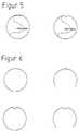
- the fastening elements are designed as tensioning elements and are optionally provided with additional seal-like adhesive before the fixation. These parts are made of resilient material, which adapt to the respective cross-section of the cavity after tensioning.
- the fasteners for receiving the components consist of smooth material or material with chamfered edges or chamfered edges or are profiled to increase the permanent clamping effect and the section modulus or consist of profiles of different geometric cross-sections, such as round or rectangular profiles hollow on the inside or made of solid material.
- the fasteners are either without or with indentations or integrated cavity of different geometric shapes, such as for example diamond, v and u-shaped or semicircular. These are considered closed Elements or divided with overlapping ends or not over the open elements reaching over the entire circumference of the drainage channel, only over at least half of the circumference of the drainage canal or as open Provide elements with a locking option or in the form of spread rings educated. By conical formation of the indentations, the Fasteners are stacked.
- a further embodiment of the device according to the invention provides that the Fasteners introduced into the existing column of the cavity connections are.
- the holding effect can be achieved through flexible, quick-setting, even during the Potting compound swelling and / or a bracing against the Drainage sewer pipe material can be achieved.
- the thickness of the fasteners should be kept as small as possible to prevent that after installation in the cavity, solids do not adhere to the Catch fasteners and lead to blockages. Going through and the robot works by means of camera surveillance.
- the distance between the fastening elements is determined by the stiffness of the cable and depends on the construction of the cavity. Although it is expedient to clean the cavities to be equipped beforehand, the method according to the invention and the associated device can also be carried out with cavities in operation.
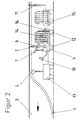
- the first exemplary embodiment shows in FIG. 1 a method in which the component 1 with the fastening elements 2 attached to it is drawn into the cavity 3 before the fastening.
- the fastening elements 2 are fastened to the component 1 at corresponding intervals in a state smaller than the inner diameter of the drainage channel.
- a robot 4 with a base unit for final positioning of the fastening elements 2 and for fastening the component 1, preferably in the upper region of the cavity 3, is introduced into the cavity 3.
- the component 1 and the fastening elements 2 lie in front of the robot 4 when viewed in the direction of travel. They are pressed with the pressure roller 5, preferably against the upper region of the cavity 3.
- the fastening elements are gripped, picked up and gripped with the gripping, positioning and fixing device 6 of the robot 4 and, if necessary, provided and positioned with seal-like adhesive from the pivotably attached adhesive device 7.
- the pretension for example held by the pin 8
- the pretension relief device 9 is released by the pretension relief device 9 and pressed by the gripping, positioning and fixing device 6 onto the inner pipe surface of the cavity 3. This creates a tight fit between component 1 and the inner tube surface of the cavity 3.
- the gripping, positioning and fixing device 6 is designed to be rotatable and / or pivotable for carrying out changes in direction. The operation is monitored by a camera 10. This process is completed with the fixed fastener 11.
- the robot 4 can be adapted to different channel diameters by changing the pressure roller 5, the gripping, positioning and fixing device 6 or the driving device 12.
- the fastening elements 2 according to FIG. 5 which are prestressed as closed elements with or without indentations by deformation, as shown in FIG.
- the second exemplary embodiment shows in FIG. 2 a method in which a component 1 is also drawn into a cavity 3, but the fastening elements 2 are only installed subsequently.
- the robot is introduced, the fastening elements 2 are positioned and fastened in accordance with the first exemplary embodiment, but the fastening elements 2 are pretensioned in a magazine 13 in front of the robot 4 or in a magazine 14 in the robot or in a magazine 15 behind the robot. If necessary, they are removed with the support of a feed device 16.
- the same fastening elements 2 as in the first exemplary embodiment are used and additionally the fastening element 2 according to FIG. 9, which is designed as spread rings.
- the third exemplary embodiment shows in FIG. 3 a method in which the Component 1 drawn into the cavity 3 and the robot 4 corresponding to the first Embodiment is introduced, but the fasteners 2nd not biased in the magazine compared to the second embodiment.
- the Fastening elements 2 are with the gripping device 17 of the robot 4 and optionally with the support of a feed unit 16, the magazine 13 taken.
- the fasteners 2 are pretensioned by gripping the Beginning of the fasteners 2 with the guide pliers 18 and simultaneously Feed and possibly rotary movement or swivel movement or rotary and
- the fastening elements 2 can likewise be provided with seal-like adhesive from the adhesive device 7 working in all directions of movement. The positioning and fixing is carried out by pressing the fastening elements 2 with the guide pliers 18 and 19 against the inner surface of the cavity 3. This in turn creates a tight fit between component 1 and the inner surface of the cavity 3.
- the feed device 17 and the guide tongs 18 and 19 are designed to be movable in order to carry out changes in direction.
- the work process is also monitored by a camera 10 and is completed with the fixed fastening element 11.
- the robot 4 can be adapted to different cavity diameters by changing the pressure roller 5, the guide tongs 18 and 19 or the driving device 12.
- the entire fastening elements 2, which are shown in FIGS. 5 to 9, are used, the fastening elements 2 with cavity and closed web shown in FIG. 9 not being able to be used.
- the fourth exemplary embodiment shows in FIG. 4 a method in which the fastening elements 2 are glued on.
- the introduction of the component 1 and the robot 4 into the cavity 3 takes place analogously to the second exemplary embodiment, but the fastening elements 2 lie loosely in the magazine 13, 14 or 15.
- the fastening elements 2 are with the gripping, positioning and fixing device 6 of the robot 4, optionally with the support of a feed device 16, and provided and positioned with a quick-adhesive agent from the adhesive device 7 working in all directions of movement.
- the fixation takes place by pressing the fastening elements 2 with the gripping, positioning and fixing device 6 onto the inner tube surface of the cavity 3. This creates a non-positive connection between the component 1 and the inner tube surface of the cavity 3.
- the further method steps correspond to the second embodiment.
- the robot is adapted to different cavity cross sections according to the first embodiment.
- the fastening elements 2 according to FIG. 6 and according to FIG. 9 are used for this exemplary embodiment, with the exception of those which are designed with a closed cavity and as closed elements.
- the fifth exemplary embodiment shows in FIG. 10 the gripping, positioning and fixing device 6, which comprises a receiving disk 21 which is arranged and rotatably mounted in the channel axis and which in turn comprises guide elements which move in the radial direction to the channel wall and which are designed as segments 22 and 23 , consists.
- the segment 22 is provided with a recess for receiving the indentation of the fastening element 2.
- Holding devices 24 are attached to the segments 23, which clamp the fastening element 2 after the gripping process and secure it during the positioning and fixing process.
- the fastening element 2 is pushed in the pretensioned state by a magazine 13, 14 or 15 attached in front of, behind or in the robot 4 known per se by the gripping device onto the receiving disc 21 and held with the holding devices 24 in such a way that the fastening element 2 snaps open during the movement of the segments 22 and 23 does not occur.
- the inclusion of the component 1 is by the movement of the segment 22 in which the indentation of the fastening element 2 is in the radial direction reached.
- the component 1 is positioned by rotating the receiving disk 21 in Circumferential direction.
- the fastening element 2 is finally fixed by moving the segments 23 in the radial direction.
- the holding devices 24 automatically release the fastening element 2 at the end of the fixing process.
- the movements of the receiving disc 21, the segments 22 and 23 and the holding devices 24 are carried out by hydraulic, pneumatic or electrical drive.
- the sixth exemplary embodiment shows in FIG. 11 the gripping, positioning and fixing device 6, which consists of a receiving disk 21 which is arranged in the channel axis so as to be rotatable and pivotable, which in turn consists of guide elements which move in the radial direction and are designed as segments 22 and 23, consists.
- the segment 22 is provided with a recess for receiving the indentation of the fastening element 2.
- Holding devices 24 are attached to the segments 23 and hold the fastening element 2 during the gripping, positioning and fixing process. In the non-prestressed state, the fastening element 2 is pushed by a gripping device onto the receiving disk 21 by a magazine 13, 14 or 15 mounted in front, behind or in the robot known per se.
- the fastening element 2 is received on the segments 22 and 23.
- the holding devices 24 fastened to the segments 23 are pushed individually over the fastening element 2 depending on the path, so that the fastening element 2 snaps open when the segments move 22 and 23 is omitted.
- the inclined receiving disk 21, with the fastening element 2 located thereon, is brought into the assembly position perpendicular to the cavity axis.
- the further training corresponds to the fifth embodiment.
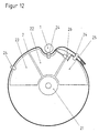
- the seventh exemplary embodiment shows in FIG. 12 the gripping, positioning and fixing device 6, which comprises a rotatably mounted receiving disc 21 arranged in the cavity axis, the guide elements which move in the radial direction to the cavity wall and which are designed as segments 22, 23 and 25 are.
- the segment 22 is provided with a recess for receiving the indentation of the fastening element 2.
- the segment 25 is provided with a sliding device 26 for tensioning the fastening element 2 by moving the ends of the fastening element 2 apart.
- Holding devices 24 are attached to the segments 22, 23 and 25 and hold the fastening element 2 during the positioning and fixing process.
- the fastening element 2 is pushed in the pretensioned state by a magazine 13, 14 or 15 mounted in front, behind or in the robot 4 known per se through the gripping device onto the receiving disk 21.
- the component 1 is received by the movement of the receiving disc 21 in the radial direction.
- the cable 1 is positioned by rotating and moving the receiving disk 21.
- the fastening element 2 is finally fixed by actuating the sliding device 26 attached to the segment 25 to move the ends of the fastening element 2 apart.
- the holding devices 24 automatically release the fastening element 2 at the end of the fixing process.
- the movements of the receiving disc 21, the segments 22, 23 and 25, the holding devices 24 and the sliding device 26 are carried out by hydraulic, pneumatic or electrical drive.
Landscapes
- Physics & Mathematics (AREA)
- General Physics & Mathematics (AREA)
- Optics & Photonics (AREA)
- Engineering & Computer Science (AREA)
- General Engineering & Computer Science (AREA)
- Mechanical Engineering (AREA)
- Installation Of Indoor Wiring (AREA)
- Manipulator (AREA)
- Slide Fasteners, Snap Fasteners, And Hook Fasteners (AREA)
- Laying Of Electric Cables Or Lines Outside (AREA)
- Automatic Assembly (AREA)
- Lining Or Joining Of Plastics Or The Like (AREA)
- Portable Nailing Machines And Staplers (AREA)
- Superconductors And Manufacturing Methods Therefor (AREA)
Claims (25)
- Procédé pour mettre en place, positionner et fixer des éléments, en particulier des tubes, des câbles, des barres ou des fils dans des volumes creux de différentes sections, en particulier des canaux d'assainissement, au moyen d'un robot qui soit se déplace par lui-même, soit est tiré par un câble dans le canal, qui porte ou non des éléments de fixation, introduit dans le volume creux et accueille et positionne l'élément,
caractérisé en ce que
les éléments de fixation (2) ou bien sont introduits dans le volume creux (3) avec l'élément (1), ou bien sont extraits d'un magasin (13, 14, 15) situé devant, sur ou derrière le robot (4) et placés dans des positions choisies à l'avance dans le volume creux, mis en relation avec l'élément (1), appliqués en pression sur le sommet du volume creux (3) et fixés par tension ou par tension et enduction de la face des éléments de fixation (2) en regard de la surface du volume creux (3) au moyen d'un adhésif du genre joint d'étanchéité, ou par collage et enduction de la surface du volume creux (3) au moyen d'un agent de collage rapide. - Procédé selon la revendication 1,
caractérisé en ce que
les éléments de fixation (2), extraits du magasin (13, 14, 15) où ils sont empilés très serrés les uns derrière les autres ou les uns sur les autres ou les uns à côté des autres ou décalés obliquement ou en combinaison, sont introduits dans le volume creux à l'état précontraint ou façonné, ou après précontrainte ou façonnage effectué par le magasin (13, 14, 15), ou se trouvent à l'intérieur ou à l'extérieur du magasin (13, 14, 15) sous la forme d'un matériau sans fin. - Procédé selon l'une quelconque des revendications 1 et 2,
caractérisé en ce que
les éléments de fixation (2) sont fixés de préférence dans des fentes de liaison du volume creux. - Dispositif pour la mise en oeuvre du procédé selon l'une quelconque des revendications 1 à 3, comprenant un robot avec une unité de base et un dispositif de mise en pression pour accueillir l'élément, ainsi qu'une caméra de surveillance de l'avancement et du travail,
caractérisé en ce que
le robot (4) est équipé d'un dispositif (6) de saisie, de positionnement et de fixation composé d'un dispositif d'application sous pression et/ou de guidage, et éventuellement d'un dispositif de collage (7) et d'un ou plusieurs magasins (13) ou (14) ou (15) pour accueillir les éléments de fixation (2) et également d'un dispositif de libération de précontrainte (9) et, dans le cas d'utilisation d'un matériau sans fin, d'un dispositif de coupe (20) pour couper le matériau destiné aux éléments de fixation (2). - Dispositif selon la revendication 4,
caractérisé en ce que
le dispositif de guidage est composé d'un ou plusieurs galets de guidage (17) ou d'un ou plusieurs disques de guidage ou d'un ou plusieurs segments de guidage ou d'un ou plusieurs bras de guidage (18) et (19) équipés d'un outil, ou d'une combinaison de ces éléments éventuellement mobiles et/ou coulissants. - Dispositif selon l'une quelconque des revendication 4 et 5,
caractérisé en ce que
le dispositif est un disque de réception (21) tournant ou tournant et basculant dans toutes les directions et servant à accueillir les éléments de fixation (2), ce disque étant constitué par un ou plusieurs éléments de guidage équipés d'un ou plusieurs dispositifs de maintien (24) servant à maintenir l'élément de fixation (2) pendant l'opération de saisie, positionnement et fixation. - Dispositif selon la revendication 6,
caractérisé en ce que
le dispositif de réception (21) est plus petit que le diamètre du canal et se trouve devant, sur ou derrière le robot (4) et le disque de réception (21), les éléments de guidage et le dispositif de maintien (24) ont leurs mouvements assurés par un entraínement hydraulique, pneumatique ou électrique ou par une combinaison de ces modes d'entraínement. - Dispositif selon l'une quelconque des revendications 5 à 7,
caractérisé en ce que
les segments de guidage (22, 23, 25) sont constitués par des galets, des corps de glissement ou des broches, ou par une combinaison de ces éléments. - Dispositif selon l'une quelconque des revendications 5 à 8,
caractérisé en ce que
les segments de guidage sont adaptés au contour des éléments de fixation (2), ou inversement. - Dispositif selon l'une quelconque des revendications 5 à 9,
caractérisé en ce que
le mouvement des segments de guidage a lieu en direction radiale et/ou axiale. - Dispositif selon l'une quelconque des revendications 5 à 10,
caractérisé en ce qu'
un ou plusieurs segments (25) sont équipés d'un mécanisme assurant le déplacement relatif des extrémités des éléments de fixation (2) afin de mettre ceux-ci en tension. - Dispositif selon l'une quelconque des revendications 5 à 11,
caractérisé en ce que
les éléments de guidage présentent un ou plusieurs évidements de formes géométriques diverses pour accueillir la bosse de l'élément de fixation (2), ou ne présentent aucun évidement et sont montés perpendiculairement à l'axe principal du disque de réception (21) soit dans un plan soit en étant décalés en direction axiale. - Dispositif selon l'une quelconque des revendications 4 à 12,
caractérisé en ce que
le dispositif de maintien (24) est constitué par un mécanisme de serrage ou par une unité agissant par attraction magnétique ou par aspiration ou par une combinaison de ces deux unités. - Dispositif selon l'une quelconque des revendications 6 à 13,
caractérisé en ce que
le dispositif de maintien (24) est intégré au disque de réception (21) ou est un composant séparé, par exemple sous la forme d'un panier ou d'un objet du genre capuchon. - Dispositif selon l'une quelconque des revendications 6 à 14,
caractérisé en ce que
les segments de guidage se déplacent individuellement, ou en même temps pour certains ou pour tous. - Dispositif selon l'une quelconque des revendications 6 à 15,
caractérisé en ce que
le début et la fin des mouvements du disque de réception (21), des segments de guidage et du dispositif de maintien (24) sont obtenus par la manoeuvre d'un ou plusieurs contacteurs ou par le réglage préalable d'un ou plusieurs limiteurs de force. - Dispositif selon l'une quelconque des revendications 4 à 16,
caractérisé en ce que
les éléments de fixation (2) sont des éléments de tension faits d'un matériau élastique et adaptés à la section du volume creux (3). - Dispositif selon l'une quelconque des revendications 4 à 17,
caractérisé en ce que
les éléments de fixation (2), quand ils n'ont pas la forme d'éléments de tension, sont, avant la fixation, garnis complémentairement d'un agent de collage rapide. - Dispositif selon l'une quelconque des revendications 4 à 18,
caractérisé en ce que
les éléments de fixation (2) sont faits d'un matériau lisse ou d'un matériau à bords repliés et/ou chanfreinés, ou sont constitués par des profilés de sections géométriques diverses. - Dispositif selon l'une quelconque des revendications 4 à 19,
caractérisé en ce que
les éléments de fixation (2) présentent ou non des bosses de formes géométriques diverses, ouvertes vers le haut ou vers le bas, ou sont équipés de volumes creux fermés ou fendus de formes géométriques diverses. - Dispositif selon l'une quelconque des revendications 4 à 20,
caractérisé en ce que
les éléments de fixation (2) sont des éléments fermés, ou ils sont ouverts avec superposition de leurs extrémités, ou ils sont des éléments ouverts ne couvrant pas toute la périphérie du volume creux (3). - Dispositif selon la revendication 21,
caractérisé en ce que
les éléments de fixation ouverts (2) sont équipés d'un dispositif de verrouillage. - Dispositif selon l'une quelconque des revendications 21 ou 22,
caractérisé en ce que
les éléments de fixation ouverts (2) ont la forme d'anneaux à expansion. - Dispositif selon l'une quelconque des revendications 4 à 23,
caractérisé en ce que
les éléments de fixation (2) peuvent être empilés grâce à la forme conique de leurs bossages. - Dispositif selon l'une quelconque des revendications 4 à 24,
caractérisé en ce que
les éléments de fixation (2) sont introduits dans des fentes des liaisons du volume creux et sont scellés au moyen d'une masse coulée flexible, durcissant et/ou foisonnant rapidement.
Applications Claiming Priority (4)
| Application Number | Priority Date | Filing Date | Title |
|---|---|---|---|
| DE19744006A DE19744006A1 (de) | 1997-09-26 | 1997-09-26 | Verfahren und Vorrichtung zum Einbringen, Positionieren und Befestigen von Bauteilen in Hohlräumen unterschiedlicher Querschnitte |
| DE19744006 | 1997-09-26 | ||
| DE19751415A DE19751415C2 (de) | 1997-09-26 | 1997-11-14 | Vorrichtung zum Greifen, Positionieren und Fixieren von Befestigungselementen in Hohlräumen unterschiedlicher Querschnitte |
| DE19751415 | 1997-11-14 |
Publications (2)
| Publication Number | Publication Date |
|---|---|
| EP0905433A1 EP0905433A1 (fr) | 1999-03-31 |
| EP0905433B1 true EP0905433B1 (fr) | 2002-04-17 |
Family
ID=26040603
Family Applications (1)
| Application Number | Title | Priority Date | Filing Date |
|---|---|---|---|
| EP98250326A Expired - Lifetime EP0905433B1 (fr) | 1997-09-26 | 1998-09-15 | Procédé et dispositif pour l'installation, le positionnement et la fixation de pièces dans des cavités avec une section transversale divergente |
Country Status (6)
| Country | Link |
|---|---|
| EP (1) | EP0905433B1 (fr) |
| AT (1) | ATE216474T1 (fr) |
| DE (2) | DE19751415C2 (fr) |
| DK (1) | DK0905433T3 (fr) |
| ES (1) | ES2172861T3 (fr) |
| PT (1) | PT905433E (fr) |
Families Citing this family (10)
| Publication number | Priority date | Publication date | Assignee | Title |
|---|---|---|---|---|
| HK1053195B (zh) | 2000-08-07 | 2008-08-22 | 芦森工业株式会社 | 给地下管道内敷设通信电缆的方法及其敷设构造以及敷设用的部件 |
| DE10148257A1 (de) * | 2001-09-30 | 2003-04-17 | Epros Umweltschutztechnik Gmbh | Verfahren zum Verlegen von mit Harz getränkten Gewebestreifen und einen Verlegeroboter zur Durchführung des Verfahrens |
| CN100381849C (zh) * | 2004-07-08 | 2008-04-16 | 上海交通大学 | 排水管道内通讯光缆的挂装方法 |
| FR2893695B1 (fr) * | 2005-11-21 | 2009-04-17 | Sogetrel Sa | Installation d'elements de soutien ponctuel d'un cable dans une canalisation |
| FR2902484B1 (fr) * | 2006-06-15 | 2010-11-05 | Sogetrel | "procede d'installation de cables, gaines et analogues dans une canalisation non visitable et dispositif pour sa mise en oeuvre" |
| NL2006062C2 (en) * | 2011-01-25 | 2012-07-30 | Jelcer Ip B V | A cable fastening element and use thereof for fastening of a cable into a tube. |
| GB2509093A (en) * | 2012-12-20 | 2014-06-25 | Balfour Beatty Plc | Vehicle for cable or pipe installation in tunnels |
| CN105240644B (zh) * | 2015-07-31 | 2018-01-02 | 厦门安越非开挖工程技术股份有限公司 | 一种管道裂缝修复装置和修复方法 |
| CN111856683B (zh) * | 2020-08-06 | 2023-05-02 | 南宁职业技术学院 | 一种基于通信设计的地下光缆走线装置及地下走线方法 |
| CN111856672B (zh) * | 2020-08-06 | 2023-03-24 | 南宁职业技术学院 | 一种通信工程用防干扰数据传输线及其走线装置 |
Family Cites Families (11)
| Publication number | Priority date | Publication date | Assignee | Title |
|---|---|---|---|---|
| DE1650994A1 (de) | 1967-02-27 | 1970-12-03 | Malmstroem Sven Erik | Kunststoffschelle fuer elektrische Kabel,Rohrleitungen u.dgl. |
| GB2129627B (en) * | 1982-09-22 | 1986-12-10 | Water Res Centre | Installation of communications cables |
| DE3501676A1 (de) | 1984-02-11 | 1985-08-22 | Günter 5880 Lüdenscheid Mesenhöller | Schelle zur befestigung von rohren |
| GB2154808B (en) | 1984-02-21 | 1987-09-09 | Water Res Centre | Installation of communications cables |
| GB2154695B (en) * | 1984-02-21 | 1987-08-19 | Water Res Centre | Installation of communications cables |
| WO1987004192A1 (fr) * | 1986-01-13 | 1987-07-16 | Maschinenfabrik Andritz Actiengesellschaft | Dispositif et procede pour le traitement de surface de feuillards avec des liquides |
| JPS637121A (ja) * | 1986-06-25 | 1988-01-13 | 東京都 | 管内ケ−ブルの施設方法および施設装置 |
| DE4203718A1 (de) * | 1992-02-08 | 1993-08-12 | Ant Nachrichtentech | Lichtwellenleiter-kabelnetz und verfahren zu dessen verlegung |
| DE4401318C2 (de) * | 1993-09-04 | 1996-07-25 | Uhrig Kanaltechnik Gmbh | Vorrichtung zum Abdichten von Leckstellen in Rohren vom Rohrinnern her und Verfahren zum Abdichten der Leckstellen |
| DE19701787A1 (de) * | 1997-01-20 | 1998-07-23 | Hecht Agathe | Lichtwellenleiterkabelnetz und Verfahren zum Verlegen eines Lichtwellenleiterkabelnetzes |
| DE29700912U1 (de) * | 1997-01-20 | 1997-02-27 | Hecht, Martin, 93167 Falkenstein | Lichtwellenleiterkabelnetz |
-
1997
- 1997-11-14 DE DE19751415A patent/DE19751415C2/de not_active Expired - Fee Related
-
1998
- 1998-09-15 AT AT98250326T patent/ATE216474T1/de not_active IP Right Cessation
- 1998-09-15 EP EP98250326A patent/EP0905433B1/fr not_active Expired - Lifetime
- 1998-09-15 PT PT98250326T patent/PT905433E/pt unknown
- 1998-09-15 DE DE59803827T patent/DE59803827D1/de not_active Expired - Fee Related
- 1998-09-15 ES ES98250326T patent/ES2172861T3/es not_active Expired - Lifetime
- 1998-09-15 DK DK98250326T patent/DK0905433T3/da active
Also Published As
| Publication number | Publication date |
|---|---|
| ATE216474T1 (de) | 2002-05-15 |
| PT905433E (pt) | 2002-09-30 |
| ES2172861T3 (es) | 2002-10-01 |
| DE19751415C2 (de) | 2001-05-23 |
| DE19751415A1 (de) | 1999-06-17 |
| EP0905433A1 (fr) | 1999-03-31 |
| DK0905433T3 (da) | 2002-07-01 |
| DE59803827D1 (de) | 2002-05-23 |
Similar Documents
| Publication | Publication Date | Title |
|---|---|---|
| EP0905433B1 (fr) | Procédé et dispositif pour l'installation, le positionnement et la fixation de pièces dans des cavités avec une section transversale divergente | |
| EP0452791A1 (fr) | Outil de pressage | |
| DE4031949C2 (de) | Verfahren und Vorrichtung zur Sanierung von Abwasserkanälen | |
| EP0521822A1 (fr) | Dispositif pour le raccordement de deux gaines | |
| DE4238700C1 (de) | Vorrichtung zur Befestigung von Verbindungselementen an Rohrleitungen | |
| EP2044286B1 (fr) | Dispositif pour relier une section de barre á un élément de traction | |
| DE19744006A1 (de) | Verfahren und Vorrichtung zum Einbringen, Positionieren und Befestigen von Bauteilen in Hohlräumen unterschiedlicher Querschnitte | |
| DE19843263A1 (de) | Verfahren zum Verlegen von Verlegeobjekten in Kanälen, Vorrichtung zur Durchführung des Verfahrens sowie Mittel zur Verwendung bei dem Verfahren | |
| DE29906645U1 (de) | Durchführungs-Vorrichtung zum abgedichteten Durchführen mindestens einer Leistung durch einen in der Wand o.dgl. ausgebildeten Durchbruch | |
| DE10392209T5 (de) | Verfahren und Vorrichtung zum Ziehen eines Seils durch einen Rohrabschnitt | |
| DE19861090C2 (de) | Verfahren zum Verlegen von Verlegeobjekten in Kanälen, Vorrichtung zur Durchführung des Verfahrens, Verlegeroboter zur Durchführung des Verfahrens, sowie verlegtes Verlegeobjekt | |
| DE102018109998B4 (de) | Rohranschlusssystem | |
| DE4029996C2 (fr) | ||
| DE19835315A1 (de) | Verfahren und Hilfselement zur Sanierung insbesondere von Abwasserrohren | |
| DE4318928C1 (de) | Verfahren zur Installation eines Leitungsrohrsystems | |
| WO1989003003A1 (fr) | Procede et moyen pour commander a distance l'introduction d'un revetement pour la reparation des conduites | |
| EP1116859B1 (fr) | Outil d'assemblage et/ou de séparation de tubes | |
| DE3832399A1 (de) | Rohrhalter und verfahren zur rohrmontage mittels eines rohrhalters | |
| DE102014115646A1 (de) | Anlage zum Verlegen von Leerrohren in Abwasserkanälen | |
| DE4418330C2 (de) | Verfahren und Vorrichtung zum Ausbessern der Wandungen im Anschlußbereich eines Zweigleitungsrohres an ein Hauptleitungsrohr | |
| DE29811512U1 (de) | Kabelführungseinrichtung an Sanierungsschläuchen | |
| DE102021001061B3 (de) | Vorrichtung zum Ausziehen von Rohren | |
| EP0936478A1 (fr) | Dispositif de montage d'un chemisage dans un tuyau non accessible | |
| EP1529624A1 (fr) | Dispositif pour souder des éléments de tuyaux en matière thermoplastique | |
| DE19640697A1 (de) | Vorrichtung zum Transport und zur Manipulation eines Werkzeugs in einem Abwasserrohr eines Kanalnetzes |
Legal Events
| Date | Code | Title | Description |
|---|---|---|---|
| PUAI | Public reference made under article 153(3) epc to a published international application that has entered the european phase |
Free format text: ORIGINAL CODE: 0009012 |
|
| AK | Designated contracting states |
Kind code of ref document: A1 Designated state(s): AT BE CH DE DK ES FR GB GR IT LI NL PT SE |
|
| AX | Request for extension of the european patent |
Free format text: AL;LT;LV;MK;RO;SI |
|
| 17P | Request for examination filed |
Effective date: 19990304 |
|
| AKX | Designation fees paid |
Free format text: AT BE CH DE DK ES FR GB GR IT LI NL PT SE |
|
| 17Q | First examination report despatched |
Effective date: 20010426 |
|
| GRAG | Despatch of communication of intention to grant |
Free format text: ORIGINAL CODE: EPIDOS AGRA |
|
| GRAG | Despatch of communication of intention to grant |
Free format text: ORIGINAL CODE: EPIDOS AGRA |
|
| GRAH | Despatch of communication of intention to grant a patent |
Free format text: ORIGINAL CODE: EPIDOS IGRA |
|
| REG | Reference to a national code |
Ref country code: GB Ref legal event code: IF02 |
|
| GRAH | Despatch of communication of intention to grant a patent |
Free format text: ORIGINAL CODE: EPIDOS IGRA |
|
| GRAA | (expected) grant |
Free format text: ORIGINAL CODE: 0009210 |
|
| RAP1 | Party data changed (applicant data changed or rights of an application transferred) |
Owner name: BERLINER WASSERBETRIEBE ANSTALT DES OEFFENTLICHEN |
|
| RTI1 | Title (correction) |
Free format text: METHOD AND DEVICE FOR INSTALLING, POSITIONING AND FIXING OF PARTS IN CAVITIES OF DIVERGING CROSS SECTIONS |
|
| RAP1 | Party data changed (applicant data changed or rights of an application transferred) |
Owner name: BERLINER WASSERBETRIEBE ANSTALT DES OEFFENTLICHEN |
|
| AK | Designated contracting states |
Kind code of ref document: B1 Designated state(s): AT BE CH DE DK ES FR GB GR IT LI NL PT SE |
|
| PG25 | Lapsed in a contracting state [announced via postgrant information from national office to epo] |
Ref country code: GR Free format text: LAPSE BECAUSE OF FAILURE TO SUBMIT A TRANSLATION OF THE DESCRIPTION OR TO PAY THE FEE WITHIN THE PRESCRIBED TIME-LIMIT Effective date: 20020417 |
|
| REF | Corresponds to: |
Ref document number: 216474 Country of ref document: AT Date of ref document: 20020515 Kind code of ref document: T |
|
| REG | Reference to a national code |
Ref country code: CH Ref legal event code: EP |
|
| GBT | Gb: translation of ep patent filed (gb section 77(6)(a)/1977) |
Effective date: 20020417 |
|
| REG | Reference to a national code |
Ref country code: CH Ref legal event code: NV Representative=s name: ROTTMANN, ZIMMERMANN + PARTNER AG |
|
| REF | Corresponds to: |
Ref document number: 59803827 Country of ref document: DE Date of ref document: 20020523 |
|
| REG | Reference to a national code |
Ref country code: DK Ref legal event code: T3 |
|
| PGFP | Annual fee paid to national office [announced via postgrant information from national office to epo] |
Ref country code: PT Payment date: 20020716 Year of fee payment: 5 |
|
| PGFP | Annual fee paid to national office [announced via postgrant information from national office to epo] |
Ref country code: GR Payment date: 20020719 Year of fee payment: 5 |
|
| PGFP | Annual fee paid to national office [announced via postgrant information from national office to epo] |
Ref country code: BE Payment date: 20020805 Year of fee payment: 5 |
|
| PGFP | Annual fee paid to national office [announced via postgrant information from national office to epo] |
Ref country code: CH Payment date: 20020829 Year of fee payment: 5 Ref country code: AT Payment date: 20020829 Year of fee payment: 5 |
|
| REG | Reference to a national code |
Ref country code: GR Ref legal event code: EP Ref document number: 20020401154 Country of ref document: GR |
|
| PGFP | Annual fee paid to national office [announced via postgrant information from national office to epo] |
Ref country code: ES Payment date: 20020910 Year of fee payment: 5 |
|
| PGFP | Annual fee paid to national office [announced via postgrant information from national office to epo] |
Ref country code: GB Payment date: 20020913 Year of fee payment: 5 |
|
| PGFP | Annual fee paid to national office [announced via postgrant information from national office to epo] |
Ref country code: DK Payment date: 20020917 Year of fee payment: 5 Ref country code: SE Payment date: 20020917 Year of fee payment: 5 |
|
| PGFP | Annual fee paid to national office [announced via postgrant information from national office to epo] |
Ref country code: FR Payment date: 20020927 Year of fee payment: 5 |
|
| PGFP | Annual fee paid to national office [announced via postgrant information from national office to epo] |
Ref country code: NL Payment date: 20020930 Year of fee payment: 5 |
|
| REG | Reference to a national code |
Ref country code: PT Ref legal event code: SC4A Free format text: AVAILABILITY OF NATIONAL TRANSLATION Effective date: 20020716 |
|
| REG | Reference to a national code |
Ref country code: ES Ref legal event code: FG2A Ref document number: 2172861 Country of ref document: ES Kind code of ref document: T3 |
|
| ET | Fr: translation filed | ||
| PLBE | No opposition filed within time limit |
Free format text: ORIGINAL CODE: 0009261 |
|
| STAA | Information on the status of an ep patent application or granted ep patent |
Free format text: STATUS: NO OPPOSITION FILED WITHIN TIME LIMIT |
|
| 26N | No opposition filed |
Effective date: 20030120 |
|
| PG25 | Lapsed in a contracting state [announced via postgrant information from national office to epo] |
Ref country code: GB Free format text: LAPSE BECAUSE OF NON-PAYMENT OF DUE FEES Effective date: 20030915 Ref country code: AT Free format text: LAPSE BECAUSE OF NON-PAYMENT OF DUE FEES Effective date: 20030915 |
|
| PG25 | Lapsed in a contracting state [announced via postgrant information from national office to epo] |
Ref country code: SE Free format text: LAPSE BECAUSE OF NON-PAYMENT OF DUE FEES Effective date: 20030916 Ref country code: ES Free format text: LAPSE BECAUSE OF NON-PAYMENT OF DUE FEES Effective date: 20030916 |
|
| PGFP | Annual fee paid to national office [announced via postgrant information from national office to epo] |
Ref country code: DE Payment date: 20030917 Year of fee payment: 6 |
|
| PG25 | Lapsed in a contracting state [announced via postgrant information from national office to epo] |
Ref country code: LI Free format text: LAPSE BECAUSE OF NON-PAYMENT OF DUE FEES Effective date: 20030930 Ref country code: DK Free format text: LAPSE BECAUSE OF NON-PAYMENT OF DUE FEES Effective date: 20030930 Ref country code: CH Free format text: LAPSE BECAUSE OF NON-PAYMENT OF DUE FEES Effective date: 20030930 Ref country code: BE Free format text: LAPSE BECAUSE OF NON-PAYMENT OF DUE FEES Effective date: 20030930 |
|
| BERE | Be: lapsed |
Owner name: *BERLINER WASSERBETRIEBE ANSTALT DES OFFENTLICHEN Effective date: 20030930 |
|
| PG25 | Lapsed in a contracting state [announced via postgrant information from national office to epo] |
Ref country code: PT Free format text: LAPSE BECAUSE OF NON-PAYMENT OF DUE FEES Effective date: 20040331 |
|
| PG25 | Lapsed in a contracting state [announced via postgrant information from national office to epo] |
Ref country code: NL Free format text: LAPSE BECAUSE OF NON-PAYMENT OF DUE FEES Effective date: 20040401 |
|
| EUG | Se: european patent has lapsed | ||
| GBPC | Gb: european patent ceased through non-payment of renewal fee |
Effective date: 20030915 |
|
| REG | Reference to a national code |
Ref country code: DK Ref legal event code: EBP |
|
| REG | Reference to a national code |
Ref country code: CH Ref legal event code: PL |
|
| PG25 | Lapsed in a contracting state [announced via postgrant information from national office to epo] |
Ref country code: FR Free format text: LAPSE BECAUSE OF NON-PAYMENT OF DUE FEES Effective date: 20040528 |
|
| NLV4 | Nl: lapsed or anulled due to non-payment of the annual fee |
Effective date: 20040401 |
|
| REG | Reference to a national code |
Ref country code: PT Ref legal event code: MM4A Free format text: LAPSE DUE TO NON-PAYMENT OF FEES Effective date: 20040331 |
|
| REG | Reference to a national code |
Ref country code: FR Ref legal event code: ST |
|
| REG | Reference to a national code |
Ref country code: ES Ref legal event code: FD2A Effective date: 20030916 |
|
| PG25 | Lapsed in a contracting state [announced via postgrant information from national office to epo] |
Ref country code: DE Free format text: LAPSE BECAUSE OF NON-PAYMENT OF DUE FEES Effective date: 20050401 |
|
| PG25 | Lapsed in a contracting state [announced via postgrant information from national office to epo] |
Ref country code: IT Free format text: LAPSE BECAUSE OF NON-PAYMENT OF DUE FEES Effective date: 20050915 |