EP0905435A2 - Lasttragende Mittel für Kryostatsystemen - Google Patents
Lasttragende Mittel für Kryostatsystemen Download PDFInfo
- Publication number
- EP0905435A2 EP0905435A2 EP98116962A EP98116962A EP0905435A2 EP 0905435 A2 EP0905435 A2 EP 0905435A2 EP 98116962 A EP98116962 A EP 98116962A EP 98116962 A EP98116962 A EP 98116962A EP 0905435 A2 EP0905435 A2 EP 0905435A2
- Authority
- EP
- European Patent Office
- Prior art keywords
- pulse tube
- load bearing
- bearing means
- magnet
- stage
- Prior art date
- Legal status (The legal status is an assumption and is not a legal conclusion. Google has not performed a legal analysis and makes no representation as to the accuracy of the status listed.)
- Withdrawn
Links
Images


Classifications
-
- F—MECHANICAL ENGINEERING; LIGHTING; HEATING; WEAPONS; BLASTING
- F17—STORING OR DISTRIBUTING GASES OR LIQUIDS
- F17C—VESSELS FOR CONTAINING OR STORING COMPRESSED, LIQUEFIED OR SOLIDIFIED GASES; FIXED-CAPACITY GAS-HOLDERS; FILLING VESSELS WITH, OR DISCHARGING FROM VESSELS, COMPRESSED, LIQUEFIED, OR SOLIDIFIED GASES
- F17C3/00—Vessels not under pressure
- F17C3/02—Vessels not under pressure with provision for thermal insulation
- F17C3/08—Vessels not under pressure with provision for thermal insulation by vacuum spaces, e.g. Dewar flask
- F17C3/085—Cryostats
-
- F—MECHANICAL ENGINEERING; LIGHTING; HEATING; WEAPONS; BLASTING
- F25—REFRIGERATION OR COOLING; COMBINED HEATING AND REFRIGERATION SYSTEMS; HEAT PUMP SYSTEMS; MANUFACTURE OR STORAGE OF ICE; LIQUEFACTION SOLIDIFICATION OF GASES
- F25B—REFRIGERATION MACHINES, PLANTS OR SYSTEMS; COMBINED HEATING AND REFRIGERATION SYSTEMS; HEAT PUMP SYSTEMS
- F25B9/00—Compression machines, plants or systems, in which the refrigerant is air or other gas of low boiling point
- F25B9/14—Compression machines, plants or systems, in which the refrigerant is air or other gas of low boiling point characterised by the cycle used, e.g. Stirling cycle
- F25B9/145—Compression machines, plants or systems, in which the refrigerant is air or other gas of low boiling point characterised by the cycle used, e.g. Stirling cycle pulse-tube cycle
-
- F—MECHANICAL ENGINEERING; LIGHTING; HEATING; WEAPONS; BLASTING
- F17—STORING OR DISTRIBUTING GASES OR LIQUIDS
- F17C—VESSELS FOR CONTAINING OR STORING COMPRESSED, LIQUEFIED OR SOLIDIFIED GASES; FIXED-CAPACITY GAS-HOLDERS; FILLING VESSELS WITH, OR DISCHARGING FROM VESSELS, COMPRESSED, LIQUEFIED, OR SOLIDIFIED GASES
- F17C2203/00—Vessel construction, in particular walls or details thereof
- F17C2203/06—Materials for walls or layers thereof; Properties or structures of walls or their materials
- F17C2203/068—Special properties of materials for vessel walls
- F17C2203/0687—Special properties of materials for vessel walls superconducting
-
- F—MECHANICAL ENGINEERING; LIGHTING; HEATING; WEAPONS; BLASTING
- F17—STORING OR DISTRIBUTING GASES OR LIQUIDS
- F17C—VESSELS FOR CONTAINING OR STORING COMPRESSED, LIQUEFIED OR SOLIDIFIED GASES; FIXED-CAPACITY GAS-HOLDERS; FILLING VESSELS WITH, OR DISCHARGING FROM VESSELS, COMPRESSED, LIQUEFIED, OR SOLIDIFIED GASES
- F17C2221/00—Handled fluid, in particular type of fluid
- F17C2221/01—Pure fluids
- F17C2221/016—Noble gases (Ar, Kr, Xe)
- F17C2221/017—Helium
-
- F—MECHANICAL ENGINEERING; LIGHTING; HEATING; WEAPONS; BLASTING
- F17—STORING OR DISTRIBUTING GASES OR LIQUIDS
- F17C—VESSELS FOR CONTAINING OR STORING COMPRESSED, LIQUEFIED OR SOLIDIFIED GASES; FIXED-CAPACITY GAS-HOLDERS; FILLING VESSELS WITH, OR DISCHARGING FROM VESSELS, COMPRESSED, LIQUEFIED, OR SOLIDIFIED GASES
- F17C2227/00—Transfer of fluids, i.e. method or means for transferring the fluid; Heat exchange with the fluid
- F17C2227/03—Heat exchange with the fluid
- F17C2227/0337—Heat exchange with the fluid by cooling
- F17C2227/0341—Heat exchange with the fluid by cooling using another fluid
- F17C2227/0353—Heat exchange with the fluid by cooling using another fluid using cryocooler
-
- F—MECHANICAL ENGINEERING; LIGHTING; HEATING; WEAPONS; BLASTING
- F17—STORING OR DISTRIBUTING GASES OR LIQUIDS
- F17C—VESSELS FOR CONTAINING OR STORING COMPRESSED, LIQUEFIED OR SOLIDIFIED GASES; FIXED-CAPACITY GAS-HOLDERS; FILLING VESSELS WITH, OR DISCHARGING FROM VESSELS, COMPRESSED, LIQUEFIED, OR SOLIDIFIED GASES
- F17C2270/00—Applications
- F17C2270/05—Applications for industrial use
- F17C2270/0509—"Dewar" vessels
-
- F—MECHANICAL ENGINEERING; LIGHTING; HEATING; WEAPONS; BLASTING
- F25—REFRIGERATION OR COOLING; COMBINED HEATING AND REFRIGERATION SYSTEMS; HEAT PUMP SYSTEMS; MANUFACTURE OR STORAGE OF ICE; LIQUEFACTION SOLIDIFICATION OF GASES
- F25B—REFRIGERATION MACHINES, PLANTS OR SYSTEMS; COMBINED HEATING AND REFRIGERATION SYSTEMS; HEAT PUMP SYSTEMS
- F25B2309/00—Gas cycle refrigeration machines
- F25B2309/14—Compression machines, plants or systems characterised by the cycle used
- F25B2309/1425—Pulse tubes with basic schematic including several pulse tubes
-
- F—MECHANICAL ENGINEERING; LIGHTING; HEATING; WEAPONS; BLASTING
- F25—REFRIGERATION OR COOLING; COMBINED HEATING AND REFRIGERATION SYSTEMS; HEAT PUMP SYSTEMS; MANUFACTURE OR STORAGE OF ICE; LIQUEFACTION SOLIDIFICATION OF GASES
- F25B—REFRIGERATION MACHINES, PLANTS OR SYSTEMS; COMBINED HEATING AND REFRIGERATION SYSTEMS; HEAT PUMP SYSTEMS
- F25B9/00—Compression machines, plants or systems, in which the refrigerant is air or other gas of low boiling point
- F25B9/10—Compression machines, plants or systems, in which the refrigerant is air or other gas of low boiling point with several cooling stages
-
- F—MECHANICAL ENGINEERING; LIGHTING; HEATING; WEAPONS; BLASTING
- F25—REFRIGERATION OR COOLING; COMBINED HEATING AND REFRIGERATION SYSTEMS; HEAT PUMP SYSTEMS; MANUFACTURE OR STORAGE OF ICE; LIQUEFACTION SOLIDIFICATION OF GASES
- F25D—REFRIGERATORS; COLD ROOMS; ICE-BOXES; COOLING OR FREEZING APPARATUS NOT OTHERWISE PROVIDED FOR
- F25D19/00—Arrangement or mounting of refrigeration units with respect to devices or objects to be refrigerated, e.g. infrared detectors
- F25D19/006—Thermal coupling structure or interface
Definitions
- the present invention relates to a load bearing means for use in MRI or similar cryostat systems as support or suspension elements.
- the various radiation shields or vessels in a cryostat are cooled by means of inserting a GM-type or other type of piston-driven cryocooler and by connecting its respective cooling stages by means of thermal links located within the cryostat.
- the different stages of the cryocooler in the cryostat are usually contacted to the shields by means of copper braids or other contacting means and by a sleeve system which makes it possible to maintain and replace the cold head.
- a pulse tube refrigerator In contrast to piston-driven coolers, a pulse tube refrigerator consists of a regenerator and a pulse tube for each refrigeration stage, and these items may be arranged in many different configurations, e.g. as concentric tubes, or spaced apart with different orientations.
- the freedom in design of the pulse tube refrigerator offers new opportunities by allowing the tubes to be placed at various locations within the cryostat, the dimension of the tubes being adjusted to suit the clearances within the cryostat.
- pulse tube refrigerators have no moving parts, their service and maintenance is much reduced compared with the present-day piston-driven coolers. If pulse tube refrigerators were to replace, or be retrofitted instead of piston-drive coolers, the mean time between maintenance could be greatly increased.
- No moving parts, apart from the travelling pressure wave down the tube, means an induced level of vibrations transmitted to the internal cryostat structure which is of several orders of magnitude lower than with piston-driven coolers.
- a cooler such as soldering, bolting, screwing, clamping, gluing, welding, sliding, pressing, or by means of shrink-fitting or spring-loading or by mechanical means by, for example, using a lever-actuated contacting system.
- An aim of the present invention is to provide a pulse tube or tubes refrigerator which can also be used as a load bearing element.
- the pulse tube or tubes and the various stages as well as the regenerator tube or tubes can act as structural members or can be incorporated in structural members. It is also a well-established fact that small neck tubes of cryostats, usually of stainless steel and with diameters as small as 30 to 50 mm and a wall thickness of 0.25 to 0.8mm, can carry shield and magnet loads of more than 1500 kg. In the same way, both the thin-walled pulse tube and the regenerator tube may be used as a reinforced suspension element to carry higher loads than have been possible before.
- load bearing means comprising at least one pulse tube refrigerator including a pulse tube and at least one regenerator tube acting as at least one support or suspension member, in an MRI system.
- the pulse tube refrigerator may be an integral part of the support member.
- the pulse tube refrigerator may be a multi-stage pulse tube refrigerator.
- Single and multi-stage pulse tube refrigerators may be connected in series or in parallel.
- the pulse tube and the regenerator tube may take different geometric shapes.
- a pulse tube refrigerator When a pulse tube refrigerator is used as a suspension member it may support the thermal shields or the superconducting magnet system.
- the support member may be of the Heim/SSC/Hartwig family or Marsing type.
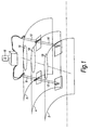
- Figure 1 shows a cooler arrangement in accordance with the present invention.
- the neck tube opening is designated 19.
- the design of the pulse tube refrigerator makes it possible to reinforce any of the tubes by wrapping layers of, for example, epoxy impregnated cloth around the tube circumference. This will give the tube additional strength depending on the amount and type of reinforcement applied. Most conveniently the tube could be heated to cure the resin. The reinforcement could be done on either or both of the pulse tube or regenerator tube.
- the PTR-tube outer surface could be further reinforced by the use of stiffeners or ribs applied both in axial or radial directions, depending on the various design constraints.
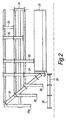
- FIG 2 shows various ways in which pulse tube refrigerators can be used as suspension elements.
- Figure 2 shows various configurations of simultaneous support and cooling using one, two, or three stage pulse tube refrigerators as follows:
- Single stage pulse tube refrigerators 28 and 34 respectively cool and support the outer shield 26 from the outer vacuum case 26a, and the inner shield 26 from the outer shield 26
- Two stage pulse tube refrigerators 30, 22, and 38 respectively cool and support the two shields from the outer vacuum case; cool and support the outer shield and the helium vessel from the outer vacuum case; cool and support the two shields and the helium vessel from the outer vacuum case, but in this case the refrigerator is extended by a thermally insulating section 36, e.g. glass reinforced epoxy resin, to support the helium vessel.
- the three stage pulse tube refrigerators 24, 32 cool and support the two shields and the helium vessel from the outer vacuum case.
- Figure 2 shows the principle of the pulse tube suspension system, the suspension system could be made of concentric design or in parallel.
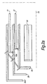
- Figure 2a shows the pulse and regenerator tubes in parallel and elongated with a tube to support the helium vessel and to keep the clearance between the radiation shields.
- FIG. 2a A two-stage, two legged pulse tube refrigerator for carrying shield loads is shown in Figure 2a, which is parallel with the horizontal cryostat axis 23. Also shown is a dual stage pulse tube refrigerator 32a which supports the loads of the thermal shields 26 from the outer vacuum case 26a.
- the type of pulse tube refrigerator shown refers to an application where the pulse tube refrigerator is integrated into a column-like support, the design of which is well-known in cryogenics design e.g. Heim, Marsing, SSC, Hartwig etc.
- cryogenics design e.g. Heim, Marsing, SSC, Hartwig etc.
- One column in particular, the Heim column achieved a load of 9000 kg for a diameter of 110 mm.
- the Heim, Hartwig, SCC, and Marsing column supports are very easily adapted to integration with the cryocooler design.
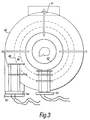
- the cryogenic vessel 40 is shown supported by a support stand 42 incorporating a pulse tube refrigerator 44.
- the refrigerator 44 is connected to the thermal shields 46, 48 for the purpose of supporting and cooling them.
- a pulse tube refrigerator 50 supporting the helium vessel structure 52 and the thermal shields 46, 48, whilst simultaneously cooling the shields.
- the suspension system 51 is a pulse tube cooler used as a
- the cooler tube and regenerator tube could be arranged concentrically or the regenerator tube could be spaced apart from the column support. It is also known that this column arrangement consisting of negative thermal expansion Hartwig type elements can support more than 5000 kilograms of weight even with a diameter as small as 50 mm and an outer wall thickness of 4 mm and thus such a system would completely satisfy the need for supporting a cold superconducting magnet. Principally, the design of the Heim column is such that there is a permanent thermal contact to the structure being attached to e.g. a magnet or vessel surface. Also this support tube material could be tailored to fit particular requirements with regard to contact pressure and force applied.
- incorporating the pulse tube in this way enables good contact to the neighbouring surfaces, and an enhanced thermal conductance value, whereas otherwise the contact resistance has to be overcome usually by applying an external force e.g. screwing together tightly.
- the integrated pulse tube refrigerator-Heim column cooler can be used as a support member for the shields being a single or multistage cooler, and it would be feasible to connect a further epoxy tube to the cold stage of the Heim column.
- This arrangement is of prime importance when using this type of pulse tube for any open and cryofree system.
- the Heim pulse tube refrigerator temperature range spans from 300K down to 4.2K (or greater than 4.2K) and is directly fitted to the coil former surface as stated above.
- FIG. 4 a cut-through section of a Heim/SCC-type column with an integrated pulse tube refrigerator is shown.
- Figure 4 further shows the temperatures experienced at the various points of contact from the outer vacuum case (OVC) side to the magnet side.
- OVC outer vacuum case
- the pulse tube refrigerator 50 is enclosed within the regenerator tube 52, and may be provided with stiffeners 54.
- Epoxy tubes 56 provide further reinforcement.
- An aluminium tube 58 allows for contraction in the direction of arrow Y.
- Insulation material 60 is provided in the spaces between the epoxy tubes and the aluminium and epoxy tube.
- the various spring-types or bellows are located at locations 62.
- the pulse tube could be fixed rigidly at the support structures to provide good thermal contacts.
- the pulse tube could also be designed so that it takes on the form of a Heim column and becomes an integral part of the support member.
- the advantage of the configuration shown in Figure 4 lies in the fact that the thermal link to the shields is most easily effected, and at the same time the heat load from the column to the shields is minimised.
- shrinkage/expansion can be accounted for by using a spring-loaded interface at position 62 or by other compensating means.
- FIG. 5 shows an example of a cryogenic stand 70 where a commercially available support element 72 is used to house the pulse tube refrigerator (not shown).
- the element 72 may have its section reinforced with copper interface plates or rings being integrated in the strut so that simple connection to the shields can be facilitated.
- a side support system 74 may also be provided.
- the pulse tube load bearing system described is extremely compact, combining various functions e.g. incorporating support of the magnet and the shields as well as thermally linking the shields for cooling. Also, the support mechanism is cooled simultaneously and enables the so-called windows (i.e. areas which cannot normally be closed completely due to assembly clearances which have to be kept) to be closed, which considerably reduces the amount of radiation being transmitted from the outer to the inner shields.
- windows i.e. areas which cannot normally be closed completely due to assembly clearances which have to be kept
- the present invention can be most efficiently used for those MRI systems, where a compact design is of utmost importance.
- the outer shell and buffer volume of a pulse tube can be located outside the vacuum vessel with the cylinder being inserted into the circular column and comprising e.g, the first or second stage of a pulse tube refrigerator.
- a further benefit of the Heim column lies in the fact that the bottom part of the tube arrangement of the pulse tube being the cold stage, could be connected to a heat pipe.
- Figure 6a shows a pulse tube refrigerator 80 attached to a wet open or standard magnet system having a heat pipe 82 connected between the refrigerator and the helium vessel 84 housing the magnet.
- the heat pipe provides rapid cooldown of the magnet.
- Figure 6b shows a pulse tube refrigerator 80 attached to a dry open or standard magnet system having a heat pipe 82 connected between the refrigerator and the magnet 85 for rapid cooldown of the magnet.
- the heat pipe fitted on the first stage facilitates cooldown of the magnet and reduces that time required to a minimum. After cooldown has been effected or the temperature of the magnet has reached its specified temperature the heat pipe takes over the function of the epoxy tube mentioned above, as a support for the magnet only.
- the heat pipe is made of epoxy or of another low-conductance material or a combination of a thin-walled metal tube with an epoxy or another plastics lining, the parasitic heat travelling down to the magnet is small.
- cryogenic heat pipe resumes operation and cools down the magnet again within a short time.
- the pulse tube's first stage 200 could be attached to the heat pipe or compressive column 202 which is directly attached to the magnet 204.
- the second stage 206 of the pulse tube comprising the regenerators 208 is then designed in parallel with the heat pipe to directly support and cool the magnet, once initial cooling has been effected. This is especially suitable for dry magnet designs.
- Figure 7 also shows an outer vacuum case 210, a radiation shield 212 at, e.g. 50K, a radiation shield 214 at, e.g. 15K, and a further compressive column 216.
- the external valve box S has a pair of hoses 218 for connection to a compressor.
- the magnet 204 is housed within a helium vessel 220.
- a pulse tube refrigerator 90 acting as a suspension member for a magnet 92 and thermal shields 96. Also shown is a pulse tube refrigerator 94 which is supported from the outer vacuum vessel 104, and which supports the helium vessel and the thermal shields 96. Provision may also be made for liquefaction at location 100.
- the reinforced pulse tube 102 could also have the additional function of acting as a stopper or bumper for transportation of the cryostat and furthermore could carry the mechanical loads being applied to the system. Its function is to limit the movement of the vessels during transport, there being no contact between vessel and stopper during normal operation.
- a load bearing twin-type pulse tube arrangement which may be a single or dual stage arrangement, for an MRI open C-type design of the zero-loss or cyrofree type.
- a magnet 112 is housed within a helium vessel 110, which is surrounded by a radiation shield 114, e.g. an 80K shield.
- First and second pulse tubes 124, 126 are connected to the helium vessel 110 via an optional heat pipe or support member 122.
- a heat exchanger 128 is connected to each of the pulse tubes 124, 126.
- a common regenerator tube 130 is provided for the pulse tubes 124, 126.
- a number of columns 116 suspend or support the helium vessel 110 and the radiation shield 114 from the outer vacuum case 120.
- An external valve box 118 has connections to the columns 116 and to a compressor via line 130.
- Optional buffer volumes 132 may also be provided.
- the twin arrangement shown in Figure 9 may supply the same temperature at different circumferential locations or preferably at two positions along the vertical or horizontal axis of an open system.
- the present invention is also of particular interest to NMR, MRI systems and related fields such as storage tanks or for HTC applications.
- the prior art suspension system normally carries the magnet loads in addition to the shield system, and thus has to be cooled. This is normally achieved by multiple heatstationing or thermal links, where each suspension element has to be cooled in order to minimise the heat leak to the helium vessel so as to minimise boil off.
- a further advantage of the present invention is that this suspension system cools itself without producing any additional heat input to the helium vessel.
- the pulse tube could be inserted into a turret of an MRI system to act as a support rod, being rigidly connected to the outer vessel container.
- the turret is of a design such that the pulse tube can be fitted or retrofitted and rigidly fixed in the neck tube assembly to carry shield and, if possible, magnet loads.
- the pulse tube refrigerator can be designed to be flexible at the point where the pulse tube connects to the regenerator tube. This is of utmost importance when retrofitting the cooler on installation sites with low ceiling height.
Landscapes
- Engineering & Computer Science (AREA)
- Physics & Mathematics (AREA)
- Thermal Sciences (AREA)
- Mechanical Engineering (AREA)
- General Engineering & Computer Science (AREA)
- Containers, Films, And Cooling For Superconductive Devices (AREA)
- Magnetic Resonance Imaging Apparatus (AREA)
Applications Claiming Priority (2)
| Application Number | Priority Date | Filing Date | Title |
|---|---|---|---|
| GB9720634A GB2329699A (en) | 1997-09-30 | 1997-09-30 | Load bearing means in cryostat systems |
| GB9720634 | 1997-09-30 |
Publications (2)
| Publication Number | Publication Date |
|---|---|
| EP0905435A2 true EP0905435A2 (de) | 1999-03-31 |
| EP0905435A3 EP0905435A3 (de) | 1999-09-01 |
Family
ID=10819765
Family Applications (1)
| Application Number | Title | Priority Date | Filing Date |
|---|---|---|---|
| EP19980116962 Withdrawn EP0905435A3 (de) | 1997-09-30 | 1998-09-08 | Lasttragende Mittel für Kryostatsystemen |
Country Status (3)
| Country | Link |
|---|---|
| EP (1) | EP0905435A3 (de) |
| JP (1) | JPH11182959A (de) |
| GB (1) | GB2329699A (de) |
Cited By (5)
| Publication number | Priority date | Publication date | Assignee | Title |
|---|---|---|---|---|
| WO2003036207A3 (en) * | 2001-10-19 | 2003-10-09 | Oxford Magnet Tech | A pulse tube refrigeration with an insulating sleeve |
| US8720210B2 (en) | 2007-05-08 | 2014-05-13 | Sumitomo Heavy Industries, Ltd. | Vibration-inhibiting reinforcement member for a cryocooler |
| PL423674A1 (pl) * | 2017-12-02 | 2019-06-03 | Czechowski Michal Ma Consulting | Urządzenie do samoobsługowej wymiany butli, zwłaszcza gazowych |
| EP4528759A1 (de) * | 2023-09-19 | 2025-03-26 | Siemens Healthcare Limited | Vorrichtung zum abdichten einer durchführung in einer kryogenen vorrichtung |
| EP4528758A1 (de) * | 2023-09-19 | 2025-03-26 | Siemens Healthcare Limited | Aufhängungsstange und magnetträgersystem |
Families Citing this family (4)
| Publication number | Priority date | Publication date | Assignee | Title |
|---|---|---|---|---|
| JP2000022226A (ja) * | 1998-06-30 | 2000-01-21 | Kobe Steel Ltd | 低温容器の冷却装置 |
| GB2441795B (en) | 2006-09-15 | 2010-06-02 | Siemens Magnet Technology Ltd | A supported superconducting magnet |
| JP2012104781A (ja) * | 2010-11-15 | 2012-05-31 | Railway Technical Research Institute | 車両に搭載されるパルス管冷凍機による高温超電導磁石冷却システム |
| DE102014203351B4 (de) * | 2014-02-25 | 2017-10-19 | Fraunhofer-Gesellschaft zur Förderung der angewandten Forschung e.V. | Auflager zur Lagerung und zur thermischen Isolation von Fluidtanks |
Family Cites Families (6)
| Publication number | Priority date | Publication date | Assignee | Title |
|---|---|---|---|---|
| GB2100987A (en) * | 1981-06-12 | 1983-01-12 | William Balfour Bald | Cryosurgical probe |
| JPH0629635Y2 (ja) * | 1986-09-09 | 1994-08-10 | 古河電気工業株式会社 | 低温保持装置 |
| US5613365A (en) * | 1994-12-12 | 1997-03-25 | Hughes Electronics | Concentric pulse tube expander |
| GB2301426B (en) * | 1995-05-16 | 1999-05-19 | Toshiba Kk | A refrigerator having a plurality of cooling stages |
| DE19548273A1 (de) * | 1995-12-22 | 1997-06-26 | Spectrospin Ag | NMR-Meßeinrichtung mit Pulsrohrkühler |
| US5647219A (en) * | 1996-06-24 | 1997-07-15 | Hughes Electronics | Cooling system using a pulse-tube expander |
-
1997
- 1997-09-30 GB GB9720634A patent/GB2329699A/en not_active Withdrawn
-
1998
- 1998-09-08 EP EP19980116962 patent/EP0905435A3/de not_active Withdrawn
- 1998-09-29 JP JP27558898A patent/JPH11182959A/ja active Pending
Cited By (6)
| Publication number | Priority date | Publication date | Assignee | Title |
|---|---|---|---|---|
| WO2003036207A3 (en) * | 2001-10-19 | 2003-10-09 | Oxford Magnet Tech | A pulse tube refrigeration with an insulating sleeve |
| US7350363B2 (en) | 2001-10-19 | 2008-04-01 | Siemens Magnet Technology, Ltd. | Pulse tube refrigerator sleeve |
| US8720210B2 (en) | 2007-05-08 | 2014-05-13 | Sumitomo Heavy Industries, Ltd. | Vibration-inhibiting reinforcement member for a cryocooler |
| PL423674A1 (pl) * | 2017-12-02 | 2019-06-03 | Czechowski Michal Ma Consulting | Urządzenie do samoobsługowej wymiany butli, zwłaszcza gazowych |
| EP4528759A1 (de) * | 2023-09-19 | 2025-03-26 | Siemens Healthcare Limited | Vorrichtung zum abdichten einer durchführung in einer kryogenen vorrichtung |
| EP4528758A1 (de) * | 2023-09-19 | 2025-03-26 | Siemens Healthcare Limited | Aufhängungsstange und magnetträgersystem |
Also Published As
| Publication number | Publication date |
|---|---|
| GB2329699A (en) | 1999-03-31 |
| GB9720634D0 (en) | 1997-11-26 |
| JPH11182959A (ja) | 1999-07-06 |
| EP0905435A3 (de) | 1999-09-01 |
Similar Documents
| Publication | Publication Date | Title |
|---|---|---|
| US6192690B1 (en) | Load bearing apparatus in NMR cryostat system | |
| EP0905524B1 (de) | Magnetanordnung für die Kernspinresonanz mit einem Halsrohr, in dem ein Pulsrohrkühler untergebracht ist | |
| US20070051116A1 (en) | Device for loss-free cryogen cooling of a cryostat configuration | |
| US6196005B1 (en) | Cryostat systems | |
| US6807812B2 (en) | Pulse tube cryocooler system for magnetic resonance superconducting magnets | |
| US20060021355A1 (en) | Cryostat configuration | |
| US20070089432A1 (en) | Cryostat configuration with cryocooler | |
| CN108692187B (zh) | 低温恒温器布置系统 | |
| US7350363B2 (en) | Pulse tube refrigerator sleeve | |
| US5113165A (en) | Superconductive magnet with thermal diode | |
| EP0905435A2 (de) | Lasttragende Mittel für Kryostatsystemen | |
| US20090301129A1 (en) | Helium and nitrogen reliquefying apparatus | |
| US20200041176A1 (en) | Cryostat assembly with superconducting magnet coil system with thermal anchoring of the mounting structure | |
| GB2465556A (en) | Cryostat suspension arrangement including turret mount | |
| US4622824A (en) | Cryostat suspension system | |
| GB2382127A (en) | Pulse tube refrigerator | |
| JP2010003943A (ja) | 断熱支持材および該断熱支持材を備えた超電導装置 | |
| US20090275476A1 (en) | Cryostat assembly | |
| US20080271467A1 (en) | Refrigerator Interface for Cryostat | |
| CN121067646A (zh) | 卧式板式换热器支撑装置 | |
| CN119983648A (zh) | 用于超导磁悬浮列车的低温制冷机储罐的隔热支撑装置 |
Legal Events
| Date | Code | Title | Description |
|---|---|---|---|
| PUAI | Public reference made under article 153(3) epc to a published international application that has entered the european phase |
Free format text: ORIGINAL CODE: 0009012 |
|
| AK | Designated contracting states |
Kind code of ref document: A2 Designated state(s): AT BE CH CY DE DK ES FI FR GB GR IE IT LI LU MC NL PT SE |
|
| AX | Request for extension of the european patent |
Free format text: AL;LT;LV;MK;RO;SI |
|
| PUAL | Search report despatched |
Free format text: ORIGINAL CODE: 0009013 |
|
| AK | Designated contracting states |
Kind code of ref document: A3 Designated state(s): AT BE CH CY DE DK ES FI FR GB GR IE IT LI LU MC NL PT SE |
|
| AX | Request for extension of the european patent |
Free format text: AL;LT;LV;MK;RO;SI |
|
| 17P | Request for examination filed |
Effective date: 19990913 |
|
| STAA | Information on the status of an ep patent application or granted ep patent |
Free format text: STATUS: THE APPLICATION HAS BEEN WITHDRAWN |
|
| 18W | Application withdrawn |
Withdrawal date: 20000118 |