EP0905442A2 - Feuerungsanlage - Google Patents
Feuerungsanlage Download PDFInfo
- Publication number
- EP0905442A2 EP0905442A2 EP98117792A EP98117792A EP0905442A2 EP 0905442 A2 EP0905442 A2 EP 0905442A2 EP 98117792 A EP98117792 A EP 98117792A EP 98117792 A EP98117792 A EP 98117792A EP 0905442 A2 EP0905442 A2 EP 0905442A2
- Authority
- EP
- European Patent Office
- Prior art keywords
- combustion chamber
- chamber
- degassing
- firing system
- secondary air
- Prior art date
- Legal status (The legal status is an assumption and is not a legal conclusion. Google has not performed a legal analysis and makes no representation as to the accuracy of the status listed.)
- Granted
Links
- 238000002485 combustion reaction Methods 0.000 title claims abstract description 82
- 239000007789 gas Substances 0.000 claims abstract description 30
- 238000007872 degassing Methods 0.000 claims description 46
- 238000010304 firing Methods 0.000 claims description 13
- 239000010881 fly ash Substances 0.000 claims description 9
- 239000004449 solid propellant Substances 0.000 claims description 2
- 239000002023 wood Substances 0.000 abstract description 8
- 239000000446 fuel Substances 0.000 description 9
- 239000002956 ash Substances 0.000 description 8
- XLYOFNOQVPJJNP-UHFFFAOYSA-N water Substances O XLYOFNOQVPJJNP-UHFFFAOYSA-N 0.000 description 8
- 239000002828 fuel tank Substances 0.000 description 7
- 229910000831 Steel Inorganic materials 0.000 description 6
- 239000010959 steel Substances 0.000 description 6
- 239000002737 fuel gas Substances 0.000 description 5
- 239000011819 refractory material Substances 0.000 description 5
- 235000002918 Fraxinus excelsior Nutrition 0.000 description 4
- 239000000567 combustion gas Substances 0.000 description 4
- 239000000428 dust Substances 0.000 description 4
- 239000000463 material Substances 0.000 description 3
- 230000004888 barrier function Effects 0.000 description 2
- 229910001385 heavy metal Inorganic materials 0.000 description 2
- 238000002156 mixing Methods 0.000 description 2
- 239000008188 pellet Substances 0.000 description 2
- 238000000926 separation method Methods 0.000 description 2
- 230000006641 stabilisation Effects 0.000 description 2
- 238000011105 stabilization Methods 0.000 description 2
- 239000002028 Biomass Substances 0.000 description 1
- 230000001133 acceleration Effects 0.000 description 1
- 238000004140 cleaning Methods 0.000 description 1
- 238000007599 discharging Methods 0.000 description 1
- 230000000694 effects Effects 0.000 description 1
- 238000011049 filling Methods 0.000 description 1
- 238000000227 grinding Methods 0.000 description 1
- 239000012774 insulation material Substances 0.000 description 1
- JEIPFZHSYJVQDO-UHFFFAOYSA-N iron(III) oxide Inorganic materials O=[Fe]O[Fe]=O JEIPFZHSYJVQDO-UHFFFAOYSA-N 0.000 description 1
- 238000011068 loading method Methods 0.000 description 1
- 238000002844 melting Methods 0.000 description 1
- 230000008018 melting Effects 0.000 description 1
- 239000002699 waste material Substances 0.000 description 1
- 239000002916 wood waste Substances 0.000 description 1
Images

Classifications
-
- F—MECHANICAL ENGINEERING; LIGHTING; HEATING; WEAPONS; BLASTING
- F23—COMBUSTION APPARATUS; COMBUSTION PROCESSES
- F23L—SUPPLYING AIR OR NON-COMBUSTIBLE LIQUIDS OR GASES TO COMBUSTION APPARATUS IN GENERAL ; VALVES OR DAMPERS SPECIALLY ADAPTED FOR CONTROLLING AIR SUPPLY OR DRAUGHT IN COMBUSTION APPARATUS; INDUCING DRAUGHT IN COMBUSTION APPARATUS; TOPS FOR CHIMNEYS OR VENTILATING SHAFTS; TERMINALS FOR FLUES
- F23L9/00—Passages or apertures for delivering secondary air for completing combustion of fuel
-
- F—MECHANICAL ENGINEERING; LIGHTING; HEATING; WEAPONS; BLASTING
- F23—COMBUSTION APPARATUS; COMBUSTION PROCESSES
- F23M—CASINGS, LININGS, WALLS OR DOORS SPECIALLY ADAPTED FOR COMBUSTION CHAMBERS, e.g. FIREBRIDGES; DEVICES FOR DEFLECTING AIR, FLAMES OR COMBUSTION PRODUCTS IN COMBUSTION CHAMBERS; SAFETY ARRANGEMENTS SPECIALLY ADAPTED FOR COMBUSTION APPARATUS; DETAILS OF COMBUSTION CHAMBERS, NOT OTHERWISE PROVIDED FOR
- F23M9/00—Baffles or deflectors for air or combustion products; Flame shields
- F23M9/08—Helical or twisted baffles or deflectors
-
- F—MECHANICAL ENGINEERING; LIGHTING; HEATING; WEAPONS; BLASTING
- F23—COMBUSTION APPARATUS; COMBUSTION PROCESSES
- F23B—METHODS OR APPARATUS FOR COMBUSTION USING ONLY SOLID FUEL
- F23B10/00—Combustion apparatus characterised by the combination of two or more combustion chambers
-
- F—MECHANICAL ENGINEERING; LIGHTING; HEATING; WEAPONS; BLASTING
- F23—COMBUSTION APPARATUS; COMBUSTION PROCESSES
- F23B—METHODS OR APPARATUS FOR COMBUSTION USING ONLY SOLID FUEL
- F23B30/00—Combustion apparatus with driven means for agitating the burning fuel; Combustion apparatus with driven means for advancing the burning fuel through the combustion chamber
- F23B30/02—Combustion apparatus with driven means for agitating the burning fuel; Combustion apparatus with driven means for advancing the burning fuel through the combustion chamber with movable, e.g. vibratable, fuel-supporting surfaces; with fuel-supporting surfaces that have movable parts
-
- F—MECHANICAL ENGINEERING; LIGHTING; HEATING; WEAPONS; BLASTING
- F23—COMBUSTION APPARATUS; COMBUSTION PROCESSES
- F23B—METHODS OR APPARATUS FOR COMBUSTION USING ONLY SOLID FUEL
- F23B40/00—Combustion apparatus with driven means for feeding fuel into the combustion chamber
- F23B40/06—Combustion apparatus with driven means for feeding fuel into the combustion chamber the fuel being fed along the fuel-supporting surface
- F23B40/08—Combustion apparatus with driven means for feeding fuel into the combustion chamber the fuel being fed along the fuel-supporting surface into pot- or trough-shaped grates
-
- F—MECHANICAL ENGINEERING; LIGHTING; HEATING; WEAPONS; BLASTING
- F23—COMBUSTION APPARATUS; COMBUSTION PROCESSES
- F23B—METHODS OR APPARATUS FOR COMBUSTION USING ONLY SOLID FUEL
- F23B5/00—Combustion apparatus with arrangements for burning uncombusted material from primary combustion
- F23B5/04—Combustion apparatus with arrangements for burning uncombusted material from primary combustion in separate combustion chamber; on separate grate
-
- F—MECHANICAL ENGINEERING; LIGHTING; HEATING; WEAPONS; BLASTING
- F23—COMBUSTION APPARATUS; COMBUSTION PROCESSES
- F23B—METHODS OR APPARATUS FOR COMBUSTION USING ONLY SOLID FUEL
- F23B80/00—Combustion apparatus characterised by means creating a distinct flow path for flue gases or for non-combusted gases given off by the fuel
- F23B80/04—Combustion apparatus characterised by means creating a distinct flow path for flue gases or for non-combusted gases given off by the fuel by means for guiding the flow of flue gases, e.g. baffles
-
- F—MECHANICAL ENGINEERING; LIGHTING; HEATING; WEAPONS; BLASTING
- F23—COMBUSTION APPARATUS; COMBUSTION PROCESSES
- F23B—METHODS OR APPARATUS FOR COMBUSTION USING ONLY SOLID FUEL
- F23B90/00—Combustion methods not related to a particular type of apparatus
- F23B90/04—Combustion methods not related to a particular type of apparatus including secondary combustion
- F23B90/06—Combustion methods not related to a particular type of apparatus including secondary combustion the primary combustion being a gasification or pyrolysis in a reductive atmosphere
-
- F—MECHANICAL ENGINEERING; LIGHTING; HEATING; WEAPONS; BLASTING
- F23—COMBUSTION APPARATUS; COMBUSTION PROCESSES
- F23L—SUPPLYING AIR OR NON-COMBUSTIBLE LIQUIDS OR GASES TO COMBUSTION APPARATUS IN GENERAL ; VALVES OR DAMPERS SPECIALLY ADAPTED FOR CONTROLLING AIR SUPPLY OR DRAUGHT IN COMBUSTION APPARATUS; INDUCING DRAUGHT IN COMBUSTION APPARATUS; TOPS FOR CHIMNEYS OR VENTILATING SHAFTS; TERMINALS FOR FLUES
- F23L5/00—Blast-producing apparatus before the fire
- F23L5/02—Arrangements of fans or blowers
-
- F—MECHANICAL ENGINEERING; LIGHTING; HEATING; WEAPONS; BLASTING
- F23—COMBUSTION APPARATUS; COMBUSTION PROCESSES
- F23M—CASINGS, LININGS, WALLS OR DOORS SPECIALLY ADAPTED FOR COMBUSTION CHAMBERS, e.g. FIREBRIDGES; DEVICES FOR DEFLECTING AIR, FLAMES OR COMBUSTION PRODUCTS IN COMBUSTION CHAMBERS; SAFETY ARRANGEMENTS SPECIALLY ADAPTED FOR COMBUSTION APPARATUS; DETAILS OF COMBUSTION CHAMBERS, NOT OTHERWISE PROVIDED FOR
- F23M9/00—Baffles or deflectors for air or combustion products; Flame shields
- F23M9/06—Baffles or deflectors for air or combustion products; Flame shields in fire-boxes
Definitions
- the present invention relates to a combustion system for combustion solid fuels, for example wood, wood waste such as chips, sawdust, Grinding dust, wood pellets, wood pellets, wood chips from the wood processing industry, wood chips, waste wood, but also biomass, according to the preamble of claim 1.
- a combustion system for combustion solid fuels for example wood, wood waste such as chips, sawdust, Grinding dust, wood pellets, wood pellets, wood chips from the wood processing industry, wood chips, waste wood, but also biomass, according to the preamble of claim 1.
- Such a furnace is known from German utility model 297 07 032.
- the cylinder through which the secondary air supply can flow simultaneously takes place on all sides with air within the combustion chamber, in particular Primary air flows around, so that an intimate mixing the gases occur.
- the cylinder provided according to the invention does not have to be a circular cylindrical one Have cross-section, but can also be polygonal or similar be square. In other words, it is sufficient that a flow tube is provided, which is partially in the combustion chamber extends and through which the secondary air supply takes place.
- the degassing chamber arranged below the combustion chamber and with this over a Passage connected can be arranged concentrically to the combustion chamber axis and by which the secondary air supply takes place.
- This embodiment has the great advantage that worked in the degassing chamber with negative pressure and that the gases from the degassing chamber into the combustion chamber first through the passage and then around the cylinder or pipe socket until it flows away from the secondary air flow get carried away. This already takes place when the Gases from the degassing chamber into the combustion chamber distribute the Gases radially outside on the combustion chamber wall.
- Operation of the degassing chamber with vacuum has the advantage that the risk of Burnback is reduced and that is essential in the main chamber less dust accumulates.
- the fan provided according to the invention for introducing secondary air can be arranged concentrically to the combustion chamber axis in an advantageous manner be, the impeller mutually movable members, for example May have chain links.
- the secondary air for post-combustion is both in rotation as well as in turbulence, which means that the furnace with one very little excess air can be operated.
- the degassing chamber can have a grate or top loading Have grate section, which is curved and preferably opposite the horizontal is inclined, as a result of which Burning is favored.
- the degassing chamber is blower-free Primary air is fed, that is, when the primary air through the in the Degassing chamber prevailing negative pressure is sucked in from the outside, since the combustion system then has a low negative pressure in the degassing chamber can be driven.
- Driving with lack of air can also be in the area the primary air intake a controlled flap can be provided, the Controls primary airflow.
- they are in the combustion chamber flowing fuel gases accelerated again by a swirl body, by imposing an angular momentum on them.
- the Rotational flow stabilized in front of the swirl body.
- the Combustion gases through the swirl body have a strong radial component imposed, causing the carried fly ash behind the swirl body flows along the wall of the combustion chamber due to the centrifugal force.
- the flow of fly ash is separated by such a flow strongly promoted by a tangential outlet opening, so that the in the Fuel gases entering the heat exchanger are almost dust and ash free are.
- the dust separation is not after Heat exchanger, but before the heat exchanger, what the great advantage is that the separated from the hot exhaust gases Fly ash - in contrast to fly ash from the cooled exhaust gases after the heat exchanger - not contaminated by heavy metals is.
- the cleaning intervals for the invention Firing system clearly compared to conventional embodiments extended. Since the ash separation is still within or at the end of the Combustion chamber takes place, it is ensured according to the invention that the fly ash separated from the hot gases, no heavy metals have accumulated.
- the swirl body preferably provided in the combustion chamber effects in addition to an improved hot gas dedusting also a stabilization the rotational flow between the secondary air supply and the swirl body, which further promotes good mixing of the fuel gases.
- this is preferred Round swirl body made of refractory material and consists of several Divide.
- the swirl body can consist of several, preferably four similarly formed fireclay elements consist of one conical middle part can be wedged within the combustion chamber.
- the swirl body can have several Have spiral gas channels, the inlet of which is preferably in the area the combustion chamber wall is arranged.
- the swirl body preferably extends over the entire Cross-section of the combustion chamber, as a result of which the entire gas flow is passed through the swirl element.
- the swirl body is preferably in the rear third of the combustion chamber or arranged at the end of the combustion chamber and is immediately in front the ash outlet opening, which is preferably arranged tangentially.
- Dedusting room is on the one hand a tangentially arranged Opening for discharging the fly ash into an underlying collecting room, on the other hand, outlets protruding into the center for the discharge of the cleaned exhaust gases in the heat exchanger.
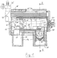
- the firing system shown in FIGS. 1 and 2 has a cylindrical and horizontally arranged boiler 10 on a raised and insulated base 12 is mounted. Inside the boiler 10 is a cylindrical combustion chamber made of refractory material (chamotte) 14 16 formed from the front end of the boiler 10 in Extends towards the end of the boiler. The combustion chamber 16 is also horizontally arranged and inside and outside in essentially circular.
- chamotte refractory material
- the front of the boiler 10 is closed with a pivotable door 18, in which a secondary air supply 20 is installed.
- the secondary air supply 20 is in the embodiment shown in Fig. 1 from a blower motor 22, on the hub of which several chain sections, that is, elements with mutually movable members, radially are attached.
- a rotary link head 24 is formed, which of sucks in outside air and conveys it horizontally into the combustion chamber 16 and imposing an angular momentum on the inflowing secondary air.
- a heat shield 26 serves to prevent the rotary link head from becoming excessive Protect heat and optimal rotation flow in the combustion chamber 16 to generate.
- the secondary air supply 20 is in a cylinder or pipe socket 27 arranged centrally, which extends from the door 18 into the combustion chamber 16 extends into so that between the cylinder 27 and the combustion chamber wall an annulus is created.
- the pipe socket 27 protrudes inside the combustion chamber.
- the combustion chamber 16 is of a cylindrical Surround steel sheath 30, being between the refractory 14 of the combustion chamber 16 and the steel jacket 30 with air or high temperature resistant insulation material filled space 32 is provided.
- the gap 32 extends essentially over the entire length of the combustion chamber 16.
- the combustion chamber coaxially in the steel jacket 30 arranged.
- the swirl body 28 Inside the combustion chamber 16 is a swirl body 28 at its end provided that extends over the entire cross section of the combustion chamber extends and which is made of refractory material.
- the swirl body 28 consists of four fireclay elements in the illustrated embodiment 28a to 28d (see FIG. 2), which are formed by a conical center piece 28e be wedged in the combustion chamber.
- Each of the fireclay elements 28a to 28d has a helix with a trapezoidal cross section and forms a Combustion chamber wall a spiral gas channel, making a total of four spiral gas channels 29a to 29d are formed, the inlet of which in the area the combustion chamber wall, that is to say radially on the outside, opens out.
- the swirl body 28 is arranged in the rear third of the combustion chamber 16 and thereby separates the dedusting chamber 34 from the combustion chamber 16, in which the refractory material 14 is still about half extends. In principle, however, the swirl body can also be omitted become.
- the dedusting chamber 34 is through the cylindrical steel jacket 30 formed, which extends substantially over the entire length of the Boiler 10 extends, one at the bottom of the dedusting chamber 34 tangentially arranged collecting opening 36 is provided for fly ash, in which a nozzle 76 is attached.
- the nozzle 76 opens into one Collection space 74, which is provided in the rear base 12.
- an outlet 38 is arranged in the region of the combustion chamber axis flows and the emerging dust-free gas through several as a heat exchanger serving boiler tubes 40, 42 (Fig. 2) to an exhaust manifold 44th (Fig. 1) leads, on which an exhaust fan 45 is arranged.
- the inside of the boiler 10 and outside of the steel jacket 30 or the boiler tubes 40, 42 existing space is filled with water that enters through water (Return) 46 fed and through a water outlet (flow) 48 is dissipated.
- the boiler 10 is therefore water-bearing or water flushed or flowed through.
- a degassing chamber 50 is arranged, which with the Combustion chamber 16 communicates via a passage 52 (FIG. 1).
- the passage 52 opens into the combustion chamber 16 at the front end thereof and is covered in the axial direction by the pipe socket 27.
- the degassing chamber 50 also has refractory material as the wall material 54, which extends partially into the water-flushed boiler 10. Furthermore, the degassing chamber 50 is covered by a cover in the form of a Firebrick vault 55 separated from the combustion chamber 16, which is convex extends over the entire width of the combustion chamber 16.
- the degassing chamber 50 has a degassing grate charged from above 58 on the right in Fig. 2 from the vertical plane of symmetry of Boiler 10 is arranged.
- a burnout grate is to the left of this plane of symmetry 60 provided by a vibrating device 61 in vibrations can be moved.
- the degassing grate 58 is concave and opposite the Horizontal inclined. However, it may be advantageous to Burnout grate 60 also inclined and trough-shaped.
- the Degassing chamber 50 or degassing grate 58 is replaced by a automatic screw conveyor 62 loaded by a fuel tank 64 extends obliquely upwards to the degassing chamber 50.
- the with an incline of at least 5 ° upwards 62 is automatically controlled and ensures a smooth Filling level to fuel from the attached fuel tank 64 feed from the degassing grate 58 from above.
- an infrared light barrier is provided, which the fuel level monitored and constant stop, so during the burn Always the same conditions prevail and always a fuel barrier is available to reduce burn-back. Because of the sloping position the screw conveyor 62 is also inside the fuel tank 64 also prevents undesirable material on the outlet wall of the fuel tank because it falls back inside.
- a primary air supply 66 is provided, which by a not shown Flap can be closed automatically and in a controlled manner.
- each Collection container 72 arranged below the degassing grate 58 and the burnout grate 60 arranged, the falling or shaken Ash and non-combustible foreign bodies.
- the fuel tank 64 filled with fuel, which automatically turns sets the screw conveyor 62 in motion and one by means of IR level sensors 68 limited amount of fuel on the degassing grate 58 and the burnout grate 60 in the degassing chamber 50 promotes. After ignition of the fuel on the degassing grate 58 the fuel is degassed.
- the combustion gases flow (from bottom to top in Fig. 1) from the Degassing grate 58 and the burnout grate 60 in the direction of the passage 52.
- the resulting during the combustion process and reacting gases forcibly and completely through the ember layer led up and away from the ashes.
- the non-combustible residues (ashes) in the collection container 72 By tracking fuel with the help of the screw conveyor 62 on the falling degassing grate 58 and by shaking the burnout grate at intervals the non-combustible residues (ashes) in the collection container 72 out.
- This causes the ashes to come out of the reacting and thus temperature increasing gas flow down in cooler zones. So there is a softening and melting the ashes prevent.
- the combustion is carried out by supplying primary air maintain the degassing grate 58.
- the from the degassing chamber 50 into the combustion chamber 16 Incoming gases initially flow in a ring around the pipe socket 27 before being carried away by the rotating secondary gas mass and burn out immediately and completely.
- In primary firing, that is, in the degassing chamber 50 remains through that Exhaust fan 45 generated negative pressure exist.
- the combustion gases flow helically on the combustion chamber wall within the combustion chamber 16 along in the direction of the swirl element 28 and flow through the spiral gas channels 29a to 29d, causing the gas flow receives another angular momentum.
Landscapes
- Engineering & Computer Science (AREA)
- Chemical & Material Sciences (AREA)
- Combustion & Propulsion (AREA)
- Mechanical Engineering (AREA)
- General Engineering & Computer Science (AREA)
- Physics & Mathematics (AREA)
- Thermal Sciences (AREA)
- Solid-Fuel Combustion (AREA)
- Breeding Of Plants And Reproduction By Means Of Culturing (AREA)
- Air Supply (AREA)
- Combustion Of Fluid Fuel (AREA)
Abstract
Description
- Fig. 1
- einen Längsschnitt durch eine Feuerungsanlage; und
- Fig. 2
- einen Querschnitt entlang der Linie II - II von Fig. 1.
- 10
- Kessel
- 12
- Sockel
- 14
- Schamotte
- 16
- Brennkammer
- 18
- Türe
- 20
- Sekundärluftzufuhr
- 22
- Gebläsemotor
- 24
- Rotationsgliederkopf
- 26
- Hitzeschild
- 27
- Rohrstutzen
- 28
- Drallkörper
- 28a - e
- Schamottelement
- 29a - d
- Gaskanal
- 30
- Stahlmantel
- 32
- Zwischenraum
- 34
- Entstaubungsraum
- 36
- Sammelöffnung
- 38
- Auslaß
- 40, 42
- Kesselrohre
- 44
- Abgassammler
- 45
- Abgasgebläse
- 46
- Wassereintritt
- 48
- Wasseraustritt
- 50
- Entgasungskammer
- 52
- Durchlaß
- 54
- feuerfestes Material
- 55
- Schamottgewölbe
- 58
- Entgasungsrost
- 60
- Ausbrandrost
- 61
- Rütteleinrichtung
- 62
- Förderschnecke
- 64
- Brennstoffbehälter
- 66
- Primärluftzuführung
- 68
- Niveausensoren
- 72
- Sammelbehälter
- 74
- Sammelraum
- 76
- Stutzen
Claims (10)
- Feuerungsanlage zur Verbrennung von festen Brennstoffen, mitdadurch gekennzeichnet, daßeiner Entgasungskammer (50);einer davon getrennten Brennkammer (16); undeiner Sekundärluftzufuhr (20), die durch ein Gebläse (24) erfolgt; wobeidie Brennkammer (16) innerhalb eines wärmeträgerdurchspülten und horizontal angeordneten Kessels (10) eingebaut ist,
ein sich teilweise in die Brennkammer (16) erstreckender, vorzugsweise konzentrisch zur Brennkammerachse angeordneter, Rohrstutzen (27) vorgesehen ist, durch den hindurch die Sekundärluftzufuhr erfolgt. - Feuerungsanlage nach Anspruch 1,
dadurch gekennzeichnet, daß
die Entgasungskammer (50) unterhalb der Brennkammer (16) angeordnet ist und mit dieser über einen Durchlaß (52) in Verbindung steht und/oder daß der Rohrstutzen im Bereich des Durchlasses (52) zu der Entgasungskammer (50) angeordnet ist. - Feuerungsanlage nach Anspruch 1 oder 2,
dadurch gekennzeichnet, daß
der Rohrstutzen (27) den Durchlaß (52) in Axialrichtung überdeckt und/oder daß sich der Rohrstutzen teilweise aus der Brennkammer (16) heraus erstreckt. - Feuerungsanlage nach zumindest einem der vorstehenden Ansprüche,
dadurch gekennzeichnet, daß
die Entgasungskammer (50) gebläsefrei mit Primärluft beschickt wird und/oder daß das Gebläse (24) durch einen Rotationsgliederkopf gebildet ist. - Feuerungsanlage nach zumindest einem der vorstehenden Ansprüche,
dadurch gekennzeichnet, daß
die Entgasungskammer (50) einen von oben beschickten Rost (58, 60) oder Rostabschnitt aufweist, der gewölbt ausgebildet und vorzugsweise gegenüber der Horizontalen geneigt angeordnet ist. - Feuerungsanlage nach zumindest einem der vorstehenden Ansprüche,
dadurch gekennzeichnet, daß
die Brennkammer in Strömungsrichtung nach der Sekundärluftzuführung einen im wesentlichen zylindrischen Querschnitt aufweist. - Feuerungsanlage nach zumindest einem der vorstehenden Ansprüche,
dadurch gekennzeichnet, daß
am Ende der Brennkammer (16) ein Entgasungsraum (34) mit einer vorzugsweise tangential angeordneten Sammelöffnung (36) für Flugasche vorgesehen ist. - Feuerungsanlage nach zumindest einem der vorstehenden Ansprüche,
dadurch gekennzeichnet, daß
mindestens ein in das Zentrum eines Entstaubungsraumes (34) führender Auslaß (38) für die Ableitung der gereinigten Gase vorgesehen ist. - Feuerungsanlage nach zumindest einem der vorstehenden Ansprüche,
dadurch gekennzeichnet, daß
die Entgasungskammer (50) durch eine Abdeckung, vorzugsweise ein Schamottgewölbe (55) von der Brennkammer (16) getrennt ist. - Feuerungsanlage nach zumindest einem der vorstehenden Ansprüche,
dadurch gekennzeichnet, daß
in der Brennkammer (16) ein Drallkörper (28) vorgesehen ist, der vorzugsweise eine axiale Breite aufweist, die etwa 10% der Brennkammerlänge beträgt, wobei der Drallkörper (28) bevorzugt zumindest einen spiralförmigen Gaskanal (29a - 29d) aufweist, dessen Einlaß vorzugsweise im Bereich der Brennkammerwand angeordnet ist.
Priority Applications (1)
| Application Number | Priority Date | Filing Date | Title |
|---|---|---|---|
| DE29823945U DE29823945U1 (de) | 1997-09-30 | 1998-09-18 | Feuerungsanlage |
Applications Claiming Priority (2)
| Application Number | Priority Date | Filing Date | Title |
|---|---|---|---|
| DE19743338 | 1997-09-30 | ||
| DE19743338A DE19743338A1 (de) | 1997-09-30 | 1997-09-30 | Feuerungsanlage |
Publications (3)
| Publication Number | Publication Date |
|---|---|
| EP0905442A2 true EP0905442A2 (de) | 1999-03-31 |
| EP0905442A3 EP0905442A3 (de) | 1999-11-03 |
| EP0905442B1 EP0905442B1 (de) | 2001-10-31 |
Family
ID=7844245
Family Applications (1)
| Application Number | Title | Priority Date | Filing Date |
|---|---|---|---|
| EP98117792A Expired - Lifetime EP0905442B1 (de) | 1997-09-30 | 1998-09-18 | Feuerungsanlage |
Country Status (3)
| Country | Link |
|---|---|
| EP (1) | EP0905442B1 (de) |
| AT (1) | ATE208025T1 (de) |
| DE (2) | DE19743338A1 (de) |
Cited By (6)
| Publication number | Priority date | Publication date | Assignee | Title |
|---|---|---|---|---|
| EP1122495A1 (de) * | 2000-02-04 | 2001-08-08 | Paul Christian | Vorrichtung zum Verbrennen von Bio-Staubmassen und Bio-Feststoffmassen |
| AT502684B1 (de) * | 2006-02-16 | 2007-05-15 | Freller Walter Ing | Vorrichtung zum verbrennen organischer stoffe |
| CN102261734A (zh) * | 2011-05-30 | 2011-11-30 | 吴渊 | 一种卧式室燃生物质锅炉 |
| CN103822203A (zh) * | 2014-03-04 | 2014-05-28 | 潘海峰 | 煤转气节能环保锅炉 |
| CN110319434A (zh) * | 2019-07-16 | 2019-10-11 | 河南农业大学 | 一种烤烟用的生物质成型颗粒燃烧一体炉 |
| CN114877364A (zh) * | 2022-05-25 | 2022-08-09 | 西安热工研究院有限公司 | 一种生物质原料均匀给料装置 |
Citations (1)
| Publication number | Priority date | Publication date | Assignee | Title |
|---|---|---|---|---|
| DE29707032U1 (de) | 1997-04-18 | 1997-06-05 | KÖB & Schäfer KG, Wolfurt | Feuerungsanlage |
Family Cites Families (5)
| Publication number | Priority date | Publication date | Assignee | Title |
|---|---|---|---|---|
| GB1546381A (en) * | 1975-03-12 | 1979-05-23 | Exxon Research Engineering Co | Burner equipment for gaseous fuel and operation thereof |
| DK148123C (da) * | 1980-12-02 | 1985-08-05 | Passat 81 A S | Centralvarmekedel med efterbraender |
| DE3434970A1 (de) * | 1984-09-24 | 1986-10-16 | Thermo-Anlagen-Technik Miehe GmbH, 3256 Coppenbrügge | Einrichtung zur minderung der feststoffpartikel- und schadstoff-anteile im zwangsgefoerderten abgasstrom aus der verbrennung von kohlenstoffhaltigen feststoffen in einem reaktorbett |
| NL8801131A (nl) * | 1988-04-29 | 1989-11-16 | Johannes Hubertus Van Breukele | Verbrandingsketel. |
| CH687346A5 (de) * | 1991-10-04 | 1996-11-15 | Chiquet Energietechnik Ag | Feuerungsvorrichtung für feste Brennstoffe. |
-
1997
- 1997-09-30 DE DE19743338A patent/DE19743338A1/de not_active Withdrawn
-
1998
- 1998-09-18 AT AT98117792T patent/ATE208025T1/de active
- 1998-09-18 DE DE59802108T patent/DE59802108D1/de not_active Expired - Lifetime
- 1998-09-18 EP EP98117792A patent/EP0905442B1/de not_active Expired - Lifetime
Patent Citations (1)
| Publication number | Priority date | Publication date | Assignee | Title |
|---|---|---|---|---|
| DE29707032U1 (de) | 1997-04-18 | 1997-06-05 | KÖB & Schäfer KG, Wolfurt | Feuerungsanlage |
Cited By (8)
| Publication number | Priority date | Publication date | Assignee | Title |
|---|---|---|---|---|
| EP1122495A1 (de) * | 2000-02-04 | 2001-08-08 | Paul Christian | Vorrichtung zum Verbrennen von Bio-Staubmassen und Bio-Feststoffmassen |
| AT502684B1 (de) * | 2006-02-16 | 2007-05-15 | Freller Walter Ing | Vorrichtung zum verbrennen organischer stoffe |
| US7942666B2 (en) | 2006-02-16 | 2011-05-17 | Walter Freller | Apparatus for burning organic substances |
| CN102261734A (zh) * | 2011-05-30 | 2011-11-30 | 吴渊 | 一种卧式室燃生物质锅炉 |
| CN103822203A (zh) * | 2014-03-04 | 2014-05-28 | 潘海峰 | 煤转气节能环保锅炉 |
| CN110319434A (zh) * | 2019-07-16 | 2019-10-11 | 河南农业大学 | 一种烤烟用的生物质成型颗粒燃烧一体炉 |
| CN110319434B (zh) * | 2019-07-16 | 2020-09-15 | 河南农业大学 | 一种烤烟用的生物质成型颗粒燃烧一体炉 |
| CN114877364A (zh) * | 2022-05-25 | 2022-08-09 | 西安热工研究院有限公司 | 一种生物质原料均匀给料装置 |
Also Published As
| Publication number | Publication date |
|---|---|
| DE59802108D1 (de) | 2001-12-06 |
| EP0905442B1 (de) | 2001-10-31 |
| ATE208025T1 (de) | 2001-11-15 |
| EP0905442A3 (de) | 1999-11-03 |
| DE19743338A1 (de) | 1999-04-01 |
Similar Documents
| Publication | Publication Date | Title |
|---|---|---|
| DE60209759T2 (de) | Verbrennungsvorrichtung | |
| EP3789672B1 (de) | Biomasse-heizanlage mit sekundärluftführung, sowie deren bestandteile | |
| DE2619316C2 (de) | Müllverbrennungsvorrichtung | |
| EP4056900B1 (de) | Biomasse-heizanlage mit einer verbesserten reinigungseinrichtung | |
| EP0905442B1 (de) | Feuerungsanlage | |
| EP1695009B1 (de) | Vergaserheizkessel für feste brennstoffe, insbesondere für strohballen, mit optimierten abgaswerten | |
| DD266836A5 (de) | Ofen | |
| EP0952396B1 (de) | Vorrichtung zum Verbrennen von stückigem Brenngut | |
| CH623398A5 (en) | Method of incinerating very moist, in particular vegetable waste fuels and incineration installation for implementing the method | |
| AT412308B (de) | Heizeinrichtung | |
| DE19828767A1 (de) | Heizkessel für die Verbrennung von festem Brennstoff | |
| EP0473618B1 (de) | Vorrichtung zum verbrennen von bio- und feststoffmassen | |
| EP2787280B1 (de) | Vorrichtung zur Verbrennung von rieselfähigem, festem Brennstoff | |
| EP2002178A1 (de) | Brennersystem, insbesondere für mit biofeststoffen befeuerte backofen | |
| EP1477736B1 (de) | Heizeinrichtung | |
| DE69202444T2 (de) | Anlage zur Abfallverbrennung. | |
| DE3126419C2 (de) | Feuerungsanlage für Stroh oder ähnliches Material | |
| EP0213512A2 (de) | Verfahren und Vorrichtung zur Verbrennung von staubförmigem Brennstoff in einer Kesselanlage | |
| CH671822A5 (en) | Solid fuel fired boiler - has after burning chamber connected to primary combustion chamber by mixing tube | |
| DE29823945U1 (de) | Feuerungsanlage | |
| DE29707032U1 (de) | Feuerungsanlage | |
| DE3727006C2 (de) | ||
| AT397551B (de) | Verbrennungsofen | |
| DE102010021370A1 (de) | Heizungssystem | |
| AT2112U1 (de) | Feuerungsanlage |
Legal Events
| Date | Code | Title | Description |
|---|---|---|---|
| PUAI | Public reference made under article 153(3) epc to a published international application that has entered the european phase |
Free format text: ORIGINAL CODE: 0009012 |
|
| AK | Designated contracting states |
Kind code of ref document: A2 Designated state(s): AT CH DE FR IT LI |
|
| AX | Request for extension of the european patent |
Free format text: AL;LT;LV;MK;RO;SI |
|
| PUAL | Search report despatched |
Free format text: ORIGINAL CODE: 0009013 |
|
| AK | Designated contracting states |
Kind code of ref document: A3 Designated state(s): AT BE CH CY DE DK ES FI FR GB GR IE IT LI LU MC NL PT SE |
|
| AX | Request for extension of the european patent |
Free format text: AL;LT;LV;MK;RO;SI |
|
| AKX | Designation fees paid | ||
| 17P | Request for examination filed |
Effective date: 19991028 |
|
| RBV | Designated contracting states (corrected) |
Designated state(s): AT CH DE FR IT LI |
|
| REG | Reference to a national code |
Ref country code: DE Ref legal event code: 8566 |
|
| 17Q | First examination report despatched |
Effective date: 20000901 |
|
| GRAG | Despatch of communication of intention to grant |
Free format text: ORIGINAL CODE: EPIDOS AGRA |
|
| GRAG | Despatch of communication of intention to grant |
Free format text: ORIGINAL CODE: EPIDOS AGRA |
|
| GRAH | Despatch of communication of intention to grant a patent |
Free format text: ORIGINAL CODE: EPIDOS IGRA |
|
| RAP1 | Party data changed (applicant data changed or rights of an application transferred) |
Owner name: KOEB WAERMETECHNIK AG |
|
| GRAH | Despatch of communication of intention to grant a patent |
Free format text: ORIGINAL CODE: EPIDOS IGRA |
|
| GRAA | (expected) grant |
Free format text: ORIGINAL CODE: 0009210 |
|
| AK | Designated contracting states |
Kind code of ref document: B1 Designated state(s): AT CH DE FR IT LI |
|
| REF | Corresponds to: |
Ref document number: 208025 Country of ref document: AT Date of ref document: 20011115 Kind code of ref document: T |
|
| REG | Reference to a national code |
Ref country code: CH Ref legal event code: EP |
|
| REF | Corresponds to: |
Ref document number: 59802108 Country of ref document: DE Date of ref document: 20011206 |
|
| ET | Fr: translation filed | ||
| PLBE | No opposition filed within time limit |
Free format text: ORIGINAL CODE: 0009261 |
|
| STAA | Information on the status of an ep patent application or granted ep patent |
Free format text: STATUS: NO OPPOSITION FILED WITHIN TIME LIMIT |
|
| 26N | No opposition filed | ||
| REG | Reference to a national code |
Ref country code: HK Ref legal event code: WD Ref document number: 1019246 Country of ref document: HK |
|
| REG | Reference to a national code |
Ref country code: CH Ref legal event code: PUE Owner name: VIESSMANN (SCHWEIZ) AG Free format text: KOEB WAERMETECHNIK AG#FAHRENSTRASSE 4#9430 ST. MARGARETHEN (CH) -TRANSFER TO- VIESSMANN (SCHWEIZ) AG#HAERDLISTRASSE 11#8957 SPREITENBACH (CH) Ref country code: CH Ref legal event code: PUE Owner name: KOEB HOLZHEIZSYSTEME GMBH Free format text: VIESSMANN (SCHWEIZ) AG#HAERDLISTRASSE 11#8957 SPREITENBACH (CH) -TRANSFER TO- KOEB HOLZHEIZSYSTEME GMBH#FLOTZBACHSTRASSE 33#6922 WOLFURT (AT) Ref country code: CH Ref legal event code: NV Representative=s name: PATENTANWAELTE SCHAAD, BALASS, MENZL & PARTNER AG |
|
| REG | Reference to a national code |
Ref country code: FR Ref legal event code: TP |
|
| PGFP | Annual fee paid to national office [announced via postgrant information from national office to epo] |
Ref country code: CH Payment date: 20141219 Year of fee payment: 17 |
|
| PGFP | Annual fee paid to national office [announced via postgrant information from national office to epo] |
Ref country code: FR Payment date: 20141219 Year of fee payment: 17 Ref country code: AT Payment date: 20141222 Year of fee payment: 17 |
|
| PGFP | Annual fee paid to national office [announced via postgrant information from national office to epo] |
Ref country code: IT Payment date: 20141222 Year of fee payment: 17 |
|
| PGFP | Annual fee paid to national office [announced via postgrant information from national office to epo] |
Ref country code: DE Payment date: 20141230 Year of fee payment: 17 |
|
| REG | Reference to a national code |
Ref country code: DE Ref legal event code: R119 Ref document number: 59802108 Country of ref document: DE |
|
| PG25 | Lapsed in a contracting state [announced via postgrant information from national office to epo] |
Ref country code: IT Free format text: LAPSE BECAUSE OF NON-PAYMENT OF DUE FEES Effective date: 20150918 |
|
| REG | Reference to a national code |
Ref country code: CH Ref legal event code: PL |
|
| REG | Reference to a national code |
Ref country code: AT Ref legal event code: MM01 Ref document number: 208025 Country of ref document: AT Kind code of ref document: T Effective date: 20150918 |
|
| REG | Reference to a national code |
Ref country code: FR Ref legal event code: ST Effective date: 20160531 |
|
| PG25 | Lapsed in a contracting state [announced via postgrant information from national office to epo] |
Ref country code: CH Free format text: LAPSE BECAUSE OF NON-PAYMENT OF DUE FEES Effective date: 20150930 Ref country code: LI Free format text: LAPSE BECAUSE OF NON-PAYMENT OF DUE FEES Effective date: 20150930 Ref country code: DE Free format text: LAPSE BECAUSE OF NON-PAYMENT OF DUE FEES Effective date: 20160401 |
|
| PG25 | Lapsed in a contracting state [announced via postgrant information from national office to epo] |
Ref country code: AT Free format text: LAPSE BECAUSE OF NON-PAYMENT OF DUE FEES Effective date: 20150918 Ref country code: FR Free format text: LAPSE BECAUSE OF NON-PAYMENT OF DUE FEES Effective date: 20150930 |