EP0905453A2 - Réchauffeur d'eau chaude sanitaire - Google Patents
Réchauffeur d'eau chaude sanitaire Download PDFInfo
- Publication number
- EP0905453A2 EP0905453A2 EP98110530A EP98110530A EP0905453A2 EP 0905453 A2 EP0905453 A2 EP 0905453A2 EP 98110530 A EP98110530 A EP 98110530A EP 98110530 A EP98110530 A EP 98110530A EP 0905453 A2 EP0905453 A2 EP 0905453A2
- Authority
- EP
- European Patent Office
- Prior art keywords
- hot water
- heat exchanger
- water tank
- secondary heat
- heating
- Prior art date
- Legal status (The legal status is an assumption and is not a legal conclusion. Google has not performed a legal analysis and makes no representation as to the accuracy of the status listed.)
- Granted
Links
- XLYOFNOQVPJJNP-UHFFFAOYSA-N water Substances O XLYOFNOQVPJJNP-UHFFFAOYSA-N 0.000 title claims abstract description 92
- 238000010438 heat treatment Methods 0.000 claims abstract description 9
- 239000008236 heating water Substances 0.000 claims description 32
- 238000000034 method Methods 0.000 claims description 13
- 238000010276 construction Methods 0.000 claims description 5
- 238000005192 partition Methods 0.000 description 3
- 230000000712 assembly Effects 0.000 description 2
- 238000000429 assembly Methods 0.000 description 2
- 210000002105 tongue Anatomy 0.000 description 2
- 239000012080 ambient air Substances 0.000 description 1
- 238000001816 cooling Methods 0.000 description 1
- 230000008878 coupling Effects 0.000 description 1
- 238000010168 coupling process Methods 0.000 description 1
- 238000005859 coupling reaction Methods 0.000 description 1
- 238000011161 development Methods 0.000 description 1
- 230000018109 developmental process Effects 0.000 description 1
- 238000004049 embossing Methods 0.000 description 1
- 239000012530 fluid Substances 0.000 description 1
- 230000006870 function Effects 0.000 description 1
- 238000009434 installation Methods 0.000 description 1
- 238000010079 rubber tapping Methods 0.000 description 1
- 239000002918 waste heat Substances 0.000 description 1
Images


Classifications
-
- F—MECHANICAL ENGINEERING; LIGHTING; HEATING; WEAPONS; BLASTING
- F24—HEATING; RANGES; VENTILATING
- F24D—DOMESTIC- OR SPACE-HEATING SYSTEMS, e.g. CENTRAL HEATING SYSTEMS; DOMESTIC HOT-WATER SUPPLY SYSTEMS; ELEMENTS OR COMPONENTS THEREFOR
- F24D3/00—Hot-water central heating systems
- F24D3/08—Hot-water central heating systems in combination with systems for domestic hot-water supply
- F24D3/087—Tap water heat exchangers specially adapted therefore
-
- F—MECHANICAL ENGINEERING; LIGHTING; HEATING; WEAPONS; BLASTING
- F24—HEATING; RANGES; VENTILATING
- F24H—FLUID HEATERS, e.g. WATER OR AIR HEATERS, HAVING HEAT-GENERATING MEANS, e.g. HEAT PUMPS, IN GENERAL
- F24H1/00—Water heaters, e.g. boilers, continuous-flow heaters or water-storage heaters
- F24H1/48—Water heaters for central heating incorporating heaters for domestic water
- F24H1/52—Water heaters for central heating incorporating heaters for domestic water incorporating heat exchangers for domestic water
-
- F—MECHANICAL ENGINEERING; LIGHTING; HEATING; WEAPONS; BLASTING
- F28—HEAT EXCHANGE IN GENERAL
- F28D—HEAT-EXCHANGE APPARATUS, NOT PROVIDED FOR IN ANOTHER SUBCLASS, IN WHICH THE HEAT-EXCHANGE MEDIA DO NOT COME INTO DIRECT CONTACT
- F28D9/00—Heat-exchange apparatus having stationary plate-like or laminated conduit assemblies for both heat-exchange media, the media being in contact with different sides of a conduit wall
- F28D9/0031—Heat-exchange apparatus having stationary plate-like or laminated conduit assemblies for both heat-exchange media, the media being in contact with different sides of a conduit wall the conduits for one heat-exchange medium being formed by paired plates touching each other
- F28D9/0043—Heat-exchange apparatus having stationary plate-like or laminated conduit assemblies for both heat-exchange media, the media being in contact with different sides of a conduit wall the conduits for one heat-exchange medium being formed by paired plates touching each other the plates having openings therein for circulation of at least one heat-exchange medium from one conduit to another
- F28D9/005—Heat-exchange apparatus having stationary plate-like or laminated conduit assemblies for both heat-exchange media, the media being in contact with different sides of a conduit wall the conduits for one heat-exchange medium being formed by paired plates touching each other the plates having openings therein for circulation of at least one heat-exchange medium from one conduit to another the plates having openings therein for both heat-exchange media
-
- F—MECHANICAL ENGINEERING; LIGHTING; HEATING; WEAPONS; BLASTING
- F28—HEAT EXCHANGE IN GENERAL
- F28D—HEAT-EXCHANGE APPARATUS, NOT PROVIDED FOR IN ANOTHER SUBCLASS, IN WHICH THE HEAT-EXCHANGE MEDIA DO NOT COME INTO DIRECT CONTACT
- F28D9/00—Heat-exchange apparatus having stationary plate-like or laminated conduit assemblies for both heat-exchange media, the media being in contact with different sides of a conduit wall
- F28D9/0093—Multi-circuit heat-exchangers, e.g. integrating different heat exchange sections in the same unit or heat-exchangers for more than two fluids
Definitions
- the invention is based on a water heater the genus of the main claim.
- Water heater this Genus as e.g. in heaters from Central heating systems are built in increased convenience of hot water because when tapping Domestic hot water is immediately available.
- a hot water tank as a separate unit trained over pipes with the secondary heat exchanger connected is.
- This version claims proportionately a lot of installation space that is required for heaters of the type mentioned above is scarce. Because of the pipe connections thermal contact between the hot water tank and Secondary heat exchanger only limited and the arrangement of one separate hot water tank is also proportionate expensive.
- the arrangement according to the invention with the features of The main claim results in a compact and space-saving Unit in which the thermal contact between the Storage volume and the secondary heat exchanger significantly is improved and the connection and Heat transfer elements in the heat exchanger plates are function-integrable. This also results in a significant cost savings compared to a separate one Hot water tank, which is expensive with the Secondary heat exchanger must be connected.
- the cooling losses of the hot water tank can be reduced if this in the course of Domestic water pipe is because the temperature of stored domestic water less than the temperature of stored heating water can be kept.
- the aspiration according to the most compact design possible, is met if the hot water tank is also made of panels is. This is also a particularly tight thermal Connection of the hot water tank to the Secondary heat exchanger possible.
- the hot water tank can be used to save space Secondary heat exchanger must be attached.
- the hot water tank is designed as a basic body the unit trained secondary heat exchanger comprehensively trained. This results in great ones Contact areas between the two modules and the further advantage that the waste heat from the secondary heat exchanger to the ambient air due to the standing Storage volume, is less than a one-sided Attachment of the hot water tank to the plate stack of the Secondary heat exchanger.
- a particularly close contact between the hot water tank and Secondary heat exchanger results when the storage volume of the hot water tank in the secondary heat exchanger is integrated.
- Hot water storage tank A "shooting" of the service or heating water through the Hot water storage tank is avoided if the Hot water storage tank in individual, connected in series Areas are divided by the water one by one be flowed through.
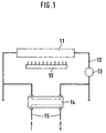
- FIG. 1 shows a simplified Representation of the common to all embodiments Basic structure
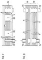
- Figures 2 to 4 each have a cross section the first, second and third embodiment
- Figure 5 enlarged a detail from Figure 4
- Figure 6 the Bottom view of a fourth embodiment
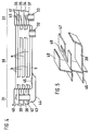
- the Figures 7 and 8 each have a cross section through the fifth and sixth embodiment.
- All of the embodiments have one from a heat source 10 heated primary heat exchanger 11 in a heating water network 12, the one via a circulation pump 13 and one Secondary heat exchanger and a hot water tank existing unit 14 leads, the heat from the heating water transfers to the water in a service water pipe 15.
- the hot water tank is in close thermal contact with the plate construction Secondary heat exchanger and can be used both for storage of domestic water, as well as heating water, or both be provided.
- a Secondary heat exchanger 18 through a stack of plates 19th formed, the 20 tight at their erected edges are interconnected and changing channels a for Limit heating water and channels b for process water.
- the Channels a and b are connected in parallel connected via passages 21, 22 which through appropriate shape of the plates 19 formed and against the intermediate, the other fluid leading Channels are sealed.
- a Connection piece 23 for one strand of the heating water network 12 attached, which leads into the passages 21. Removed from Connection piece 23 and not visible in the drawing is a second group of passages connecting the channels a and a corresponding connection piece for the another strand of the heating water network 12 is arranged.
- the incoming strand of the domestic water pipe 15 is in a hot water tank 25 performed on the Secondary heat exchanger 18 is placed and with this one Unit forms.
- a connecting piece 26 on the secondary heat exchanger 18th and a tube 27 provided through the passages 22 in the hot water tank 25 is guided.
- the tube 27 extends therein to a location 28 which removes is arranged by the group of passages 22 whose top immediately opens into the hot water tank 25. Removed from the connector 26 and not in the drawing a second group of channels b is visible connecting passages and a corresponding one Connection piece for the further strand of Service water line 15 arranged.
- the hot water tank 25 is in a large area close thermal contact with the plate 19 of the Secondary heat exchanger 18 which the upper heating water channel a limited.
- the flow in the hot water tank 25 is on this plate 19 inevitably led along and the exit of the hot water tank 25 opens out in the shortest possible way, i.e. directly into the group of service water channels b.
- the Storage volume is due to the already existing Heat exchanger function heated up, so that an additional There is no heat exchanger for the domestic hot water tank.
- FIG. 3 corresponds to that according to FIG. 2 except for the feature that the hot water tank 25th between two heating water channels a of the secondary heat exchanger is arranged so that there is an even more intense thermal contact between the heating water and the Hot water in the hot water tank 25 results.
- the hot water tank could also be exemplary embodiments be arranged on the heating water side.
- the Hot water tank even deeper in the plate stack of the Secondary heat exchanger, so that it is both from the heating water process water is also washed around in the secondary heat exchanger.
- a Secondary heat exchanger 30 a base body by a also made in panel construction Domestic hot water tank 31 is included.
- the Secondary heat exchanger 30 is on the underside Connections for the heating network 12 connected, of which one, 32, lies in the plane of the drawing and the other, not visible in the drawing, arranged away from it is.
- the internal structure of the secondary heat exchanger 30 is correct corresponds to that of Figure 2, so that not is received.
- the hot water tank 31 is with a Connection piece 33 for the incoming strand of Process water line 15 connected to an annular chamber 34 opens out, through which two further annular chambers 35, 36 are arranged.
- the annular chambers 34, 35, 36 are by plates 37, 38, 39, 40 limited, which is integral with the plates of the Secondary heat exchanger 30 are connected. This is a excellent thermal contact between the two Assemblies given.
- the annular chamber 34 is with the annular chamber 35 via an opening not visible in the drawing in the Plate 38 connected to the connecting piece 33 approximately diagonally opposite.
- the annular chamber 35 is a Opening 41 in the plate 39 connected to the annular chamber 36, which is arranged approximately coaxially to the connecting piece 33.
- the annular chamber 40 is attached to the plate 39 and pipe passed through the other plates 38, 37 42 connected to a chamber 43 which is between the lower Plate 37 and a hood 44 attached thereto is formed.
- the hood 44 extends in the area of Secondary heat exchanger 30 and engages there in the one Plate 37 arranged opening 45 through which the inflowing Service water enters the service water channels b.
- the alternative solution shown in Figure 6 for execution 4 has a secondary heat exchanger as the base body 50, which is enclosed by a heating water tank 51.
- the secondary heat exchanger 50 On the bottom is the secondary heat exchanger 50 with Connections 52, 53 for the hot water pipe 15 and one Provide connection 54 for the heating network 12.
- the inner one Structure of the secondary heat exchanger 50 and Domestic hot water tank 31 corresponds to the version Figure 4.
- the heating water tank 51 has a connection 55 for the second strand of the heating network 12, which in the lower Annulus 34 opens. This is via an opening 56 in the cover plate with the overlying ring chamber 35 connected, one of which is approximately coaxial with the terminal 55 arranged opening leads into the third annular chamber 36.
- connection 55 there is a pipe 42 in FIG. 4 corresponding channel 57 is provided, the third Annular chamber 36 to the underside of the heating water tank 51 leads.
- the channel 57 through a hood 58 with a Opening 59 in the bottom plate of the Secondary heat exchanger 50 connected to the input whose heating water channels forms.
- the special thing about the Execution according to Figure 6 is that between the Connection piece 50 and the underlying, the Annular chambers 35 and 36 connecting opening on the one hand and the leading from the annular chamber 34 into the annular chamber 35 Opening 56 on the other hand a partition 60 is provided, which penetrates all annular chambers and for example through appropriate embossing of the plates is formed.
- the Partition 60 forces one through in each annular chamber dashed line 61 indicated ring flow of the Heating water, which in the annular chambers 34 and 36 in Clockwise and in the annular chamber 35 against Runs clockwise. This makes it a particularly intense one Heat exchange between the heating water and the domestic water reached.
- FIG. 7 In the embodiment of Figure 7 are inside of a secondary heat exchanger 64 two storage spaces 65 and 66 integrated for process water, which at a connection piece 67 is supplied, the storage spaces 65, 66 in succession runs through and then in the parallel Service water channels b reaches the secondary heat exchanger. Out the process water flows through one in the drawing not visible, lying behind the connecting piece 67 Connection piece in the continuing strand of Service water line 15 from.
- the connections for the heating water and the internal connections of the parallel ones Heating water channels are in the drawing of simplicity omitted for the sake of it.
- the arrangement could also be so be that the storage spaces 65, 66 in the course of Heating water network and that as in Figure 4 individual Protruding plates with tongues into the storage spaces 65, 66.
- the embodiment of Figure 8 has one Secondary heat exchanger 70, on which a hot water tank 71st is attached, which is also carried out in panel construction is and both heating water channels a and Service water ducts b contains.
- the hot water channels b are in the hot water tank 71 in series and in Secondary heat exchanger 70 connected in parallel.
- the Heating water channels a are parallel in both assemblies 70, 71 switched.
- the channels a, b in the hot water tank 71 are internally with channels a, b in secondary heat exchanger 70 connected, so that in this case also special means and Measures for this are not required.
- the hot water tank 71 has a connection piece 72 for the incoming strand of the domestic water pipe 15 and one Connection piece 73 for the heating network 12.
- the Secondary heat exchanger 70 is with a connecting piece 74 for the heating network 12 and a connection 75 for the Continuing strand of the domestic water line 15 provided.
- the embodiment according to FIG. 8 is characterized by a particularly fast thermal coupling of the memory the secondary heat exchanger.
Landscapes
- Engineering & Computer Science (AREA)
- Mechanical Engineering (AREA)
- Physics & Mathematics (AREA)
- Thermal Sciences (AREA)
- General Engineering & Computer Science (AREA)
- Chemical & Material Sciences (AREA)
- Combustion & Propulsion (AREA)
- Water Supply & Treatment (AREA)
- Heat-Pump Type And Storage Water Heaters (AREA)
- Steam Or Hot-Water Central Heating Systems (AREA)
- Thermally Insulated Containers For Foods (AREA)
- Cookers (AREA)
- Resistance Heating (AREA)
Applications Claiming Priority (2)
| Application Number | Priority Date | Filing Date | Title |
|---|---|---|---|
| DE19742075A DE19742075A1 (de) | 1997-09-24 | 1997-09-24 | Brauchwasserbereiter |
| DE19742075 | 1997-09-24 |
Publications (4)
| Publication Number | Publication Date |
|---|---|
| EP0905453A2 true EP0905453A2 (fr) | 1999-03-31 |
| EP0905453A3 EP0905453A3 (fr) | 2001-04-11 |
| EP0905453B1 EP0905453B1 (fr) | 2003-06-18 |
| EP0905453B2 EP0905453B2 (fr) | 2006-03-01 |
Family
ID=7843430
Family Applications (1)
| Application Number | Title | Priority Date | Filing Date |
|---|---|---|---|
| EP98110530A Expired - Lifetime EP0905453B2 (fr) | 1997-09-24 | 1998-06-09 | Réchauffeur d'eau chaude sanitaire |
Country Status (3)
| Country | Link |
|---|---|
| EP (1) | EP0905453B2 (fr) |
| AT (1) | ATE243306T1 (fr) |
| DE (2) | DE19742075A1 (fr) |
Cited By (5)
| Publication number | Priority date | Publication date | Assignee | Title |
|---|---|---|---|---|
| WO2001048433A1 (fr) * | 1999-12-23 | 2001-07-05 | Alfa Laval Corporate Ab | Echangeur a plaques |
| WO2001057452A1 (fr) * | 2000-02-01 | 2001-08-09 | Alfa Laval Corporate Ab. | Dispositif de chauffage et/ou de refroidissement |
| JP2003517558A (ja) * | 1999-12-15 | 2003-05-27 | スウエプ インターナシヨナル アーベー | 板状熱交換器と温水貯蔵コンテナを備える湯沸器 |
| WO2006059208A1 (fr) * | 2004-12-01 | 2006-06-08 | Cosmogas S.R.L. | Echangeur thermique pour chaudiere combinee, et chaudiere combinee utilisant un tel echangeur thermique |
| EP1703213A1 (fr) * | 2005-02-07 | 2006-09-20 | Robert Bosch Gmbh | Chauffe-eau sanitaire |
Families Citing this family (1)
| Publication number | Priority date | Publication date | Assignee | Title |
|---|---|---|---|---|
| EP1850082A1 (fr) * | 2006-04-24 | 2007-10-31 | Sundsvall Energi AB | Echangeur de chaleur |
Family Cites Families (5)
| Publication number | Priority date | Publication date | Assignee | Title |
|---|---|---|---|---|
| DE2214711C3 (de) * | 1972-03-25 | 1979-08-23 | Egon 8222 Ruhpolding Laforce | Brauchwasserbereiter |
| AT400080B (de) * | 1989-09-14 | 1995-09-25 | Austria Email Waermetech Gmbh | Warmwasserbereitungsanlage |
| AT400362B (de) * | 1991-11-04 | 1995-12-27 | Vaillant Gmbh | Heizgerät mit einem von einer wärmequelle beaufschlagten wärmetauscher |
| GB2262593B (en) * | 1991-12-17 | 1995-04-12 | Inter Albion Ltd | An apparatus for and a method of providing hot sanitary water |
| FR2742214B1 (fr) * | 1995-12-08 | 1999-08-20 | Chaffoteaux Et Maury | Appareils generateurs d'eau chaude sanitaire et d'eau de chauffage central |
-
1997
- 1997-09-24 DE DE19742075A patent/DE19742075A1/de not_active Ceased
-
1998
- 1998-06-09 DE DE59808742T patent/DE59808742D1/de not_active Expired - Lifetime
- 1998-06-09 EP EP98110530A patent/EP0905453B2/fr not_active Expired - Lifetime
- 1998-06-09 AT AT98110530T patent/ATE243306T1/de active
Cited By (6)
| Publication number | Priority date | Publication date | Assignee | Title |
|---|---|---|---|---|
| JP2003517558A (ja) * | 1999-12-15 | 2003-05-27 | スウエプ インターナシヨナル アーベー | 板状熱交換器と温水貯蔵コンテナを備える湯沸器 |
| EP1238231B2 (fr) † | 1999-12-15 | 2007-05-16 | SWEP International AB | Chauffe-eau comprenant un echangeur a plaques et un reservoir d'eau chaude |
| WO2001048433A1 (fr) * | 1999-12-23 | 2001-07-05 | Alfa Laval Corporate Ab | Echangeur a plaques |
| WO2001057452A1 (fr) * | 2000-02-01 | 2001-08-09 | Alfa Laval Corporate Ab. | Dispositif de chauffage et/ou de refroidissement |
| WO2006059208A1 (fr) * | 2004-12-01 | 2006-06-08 | Cosmogas S.R.L. | Echangeur thermique pour chaudiere combinee, et chaudiere combinee utilisant un tel echangeur thermique |
| EP1703213A1 (fr) * | 2005-02-07 | 2006-09-20 | Robert Bosch Gmbh | Chauffe-eau sanitaire |
Also Published As
| Publication number | Publication date |
|---|---|
| EP0905453B1 (fr) | 2003-06-18 |
| DE59808742D1 (de) | 2003-07-24 |
| EP0905453A3 (fr) | 2001-04-11 |
| EP0905453B2 (fr) | 2006-03-01 |
| ATE243306T1 (de) | 2003-07-15 |
| DE19742075A1 (de) | 1999-03-25 |
Similar Documents
| Publication | Publication Date | Title |
|---|---|---|
| DE60010226T2 (de) | Gehäuseloser wärmetauscher mit turbulenzeinlage | |
| EP0653043B1 (fr) | Echangeur de chaleur | |
| EP3371540B1 (fr) | Module échangeur thermique | |
| EP0828980A1 (fr) | Echangeur de chaleur | |
| DE3630084C2 (fr) | ||
| EP0911156A1 (fr) | Arrangement pour tempérer dans une machine d'impression | |
| EP0905453B1 (fr) | Réchauffeur d'eau chaude sanitaire | |
| DE4308626C1 (de) | Mehrfachverteiler für fluidische Koaxialleitungen | |
| DE102004020602A1 (de) | Plattenwärmetauscher mit Strömungswegen für drei Wärmetauschfluide | |
| EP0057850B1 (fr) | Echangeur de chaleur pour liquides | |
| DE3509674A1 (de) | Kondensatheizkessel | |
| DE102006004756A1 (de) | Peltier-Wärmetauscher in modularer Bauweise | |
| EP1760407A1 (fr) | Distributeur pour système de chauffage et de refroidissement | |
| DE19628708B4 (de) | Wasserheizanlage | |
| DE1451246B2 (de) | Wärmetauscher mit mehreren Plattenelementen | |
| DE9214762U1 (de) | Thermische Weiche | |
| AT410713B (de) | Wasserheizanlage | |
| EP0823599B1 (fr) | Chauffe-eau à gaz | |
| DE3230351C2 (de) | Einrichtung zur Kokskühlung | |
| AT408146B (de) | Heizeinrichtung | |
| DE3009215A1 (de) | Multizyklon-entstaubungsvorrichtung fuer rauchgase | |
| DE102023120129A1 (de) | Pufferspeicher, Heizungsanlage und Verfahren zu deren Betrieb | |
| DE29716583U1 (de) | Mehrmedien-Wärmetauscheinrichtung | |
| DE102006020502A1 (de) | Anordnung eines Wärmetauscherelements | |
| DE202005007941U1 (de) | Geregelter Zwei-Zonen-Pufferspeicher für frische Trinkwassererwärmung |
Legal Events
| Date | Code | Title | Description |
|---|---|---|---|
| PUAI | Public reference made under article 153(3) epc to a published international application that has entered the european phase |
Free format text: ORIGINAL CODE: 0009012 |
|
| AK | Designated contracting states |
Kind code of ref document: A2 Designated state(s): AT DE FR GB IT |
|
| AX | Request for extension of the european patent |
Free format text: AL;LT;LV;MK;RO;SI |
|
| PUAL | Search report despatched |
Free format text: ORIGINAL CODE: 0009013 |
|
| AK | Designated contracting states |
Kind code of ref document: A3 Designated state(s): AT BE CH CY DE DK ES FI FR GB GR IE IT LI LU MC NL PT SE |
|
| AX | Request for extension of the european patent |
Free format text: AL;LT;LV;MK;RO;SI |
|
| 17P | Request for examination filed |
Effective date: 20011011 |
|
| AKX | Designation fees paid |
Free format text: AT DE FR GB IT |
|
| GRAH | Despatch of communication of intention to grant a patent |
Free format text: ORIGINAL CODE: EPIDOS IGRA |
|
| GRAH | Despatch of communication of intention to grant a patent |
Free format text: ORIGINAL CODE: EPIDOS IGRA |
|
| GRAA | (expected) grant |
Free format text: ORIGINAL CODE: 0009210 |
|
| AK | Designated contracting states |
Designated state(s): AT DE FR GB IT |
|
| REG | Reference to a national code |
Ref country code: GB Ref legal event code: FG4D Free format text: NOT ENGLISH |
|
| REF | Corresponds to: |
Ref document number: 59808742 Country of ref document: DE Date of ref document: 20030724 Kind code of ref document: P |
|
| GBT | Gb: translation of ep patent filed (gb section 77(6)(a)/1977) |
Effective date: 20031027 |
|
| ET | Fr: translation filed | ||
| PLBI | Opposition filed |
Free format text: ORIGINAL CODE: 0009260 |
|
| PLAX | Notice of opposition and request to file observation + time limit sent |
Free format text: ORIGINAL CODE: EPIDOSNOBS2 |
|
| 26 | Opposition filed |
Opponent name: VAILLANT GMBH Effective date: 20040315 |
|
| PLBB | Reply of patent proprietor to notice(s) of opposition received |
Free format text: ORIGINAL CODE: EPIDOSNOBS3 |
|
| PUAH | Patent maintained in amended form |
Free format text: ORIGINAL CODE: 0009272 |
|
| STAA | Information on the status of an ep patent application or granted ep patent |
Free format text: STATUS: PATENT MAINTAINED AS AMENDED |
|
| 27A | Patent maintained in amended form |
Effective date: 20060301 |
|
| AK | Designated contracting states |
Kind code of ref document: B2 Designated state(s): AT DE FR GB IT |
|
| GBTA | Gb: translation of amended ep patent filed (gb section 77(6)(b)/1977) |
Effective date: 20060510 |
|
| ET3 | Fr: translation filed ** decision concerning opposition | ||
| PGFP | Annual fee paid to national office [announced via postgrant information from national office to epo] |
Ref country code: AT Payment date: 20110620 Year of fee payment: 14 |
|
| REG | Reference to a national code |
Ref country code: AT Ref legal event code: MM01 Ref document number: 243306 Country of ref document: AT Kind code of ref document: T Effective date: 20120609 |
|
| PG25 | Lapsed in a contracting state [announced via postgrant information from national office to epo] |
Ref country code: AT Free format text: LAPSE BECAUSE OF NON-PAYMENT OF DUE FEES Effective date: 20120609 |
|
| PGFP | Annual fee paid to national office [announced via postgrant information from national office to epo] |
Ref country code: GB Payment date: 20130620 Year of fee payment: 16 |
|
| PGFP | Annual fee paid to national office [announced via postgrant information from national office to epo] |
Ref country code: FR Payment date: 20130703 Year of fee payment: 16 |
|
| PGFP | Annual fee paid to national office [announced via postgrant information from national office to epo] |
Ref country code: DE Payment date: 20130828 Year of fee payment: 16 |
|
| PGFP | Annual fee paid to national office [announced via postgrant information from national office to epo] |
Ref country code: IT Payment date: 20130622 Year of fee payment: 16 |
|
| REG | Reference to a national code |
Ref country code: DE Ref legal event code: R119 Ref document number: 59808742 Country of ref document: DE |
|
| GBPC | Gb: european patent ceased through non-payment of renewal fee |
Effective date: 20140609 |
|
| REG | Reference to a national code |
Ref country code: FR Ref legal event code: ST Effective date: 20150227 |
|
| REG | Reference to a national code |
Ref country code: DE Ref legal event code: R119 Ref document number: 59808742 Country of ref document: DE Effective date: 20150101 |
|
| PG25 | Lapsed in a contracting state [announced via postgrant information from national office to epo] |
Ref country code: IT Free format text: LAPSE BECAUSE OF NON-PAYMENT OF DUE FEES Effective date: 20140609 Ref country code: DE Free format text: LAPSE BECAUSE OF NON-PAYMENT OF DUE FEES Effective date: 20150101 |
|
| PG25 | Lapsed in a contracting state [announced via postgrant information from national office to epo] |
Ref country code: GB Free format text: LAPSE BECAUSE OF NON-PAYMENT OF DUE FEES Effective date: 20140609 Ref country code: FR Free format text: LAPSE BECAUSE OF NON-PAYMENT OF DUE FEES Effective date: 20140630 |