EP0905469A1 - Arme de poing pour projectiles de neutralisation. - Google Patents
Arme de poing pour projectiles de neutralisation. Download PDFInfo
- Publication number
- EP0905469A1 EP0905469A1 EP98402339A EP98402339A EP0905469A1 EP 0905469 A1 EP0905469 A1 EP 0905469A1 EP 98402339 A EP98402339 A EP 98402339A EP 98402339 A EP98402339 A EP 98402339A EP 0905469 A1 EP0905469 A1 EP 0905469A1
- Authority
- EP
- European Patent Office
- Prior art keywords
- ammunition
- projectile
- barrel
- handgun
- projectiles
- Prior art date
- Legal status (The legal status is an assumption and is not a legal conclusion. Google has not performed a legal analysis and makes no representation as to the accuracy of the status listed.)
- Granted
Links
- 230000003472 neutralizing effect Effects 0.000 title description 2
- 239000004033 plastic Substances 0.000 claims abstract description 11
- 229920003023 plastic Polymers 0.000 claims abstract description 11
- 239000000843 powder Substances 0.000 claims abstract description 9
- 238000006386 neutralization reaction Methods 0.000 claims description 12
- 239000002245 particle Substances 0.000 claims description 4
- 239000007787 solid Substances 0.000 claims description 4
- 210000000056 organ Anatomy 0.000 claims description 2
- 238000009527 percussion Methods 0.000 abstract description 5
- 239000000463 material Substances 0.000 abstract description 4
- 239000003365 glass fiber Substances 0.000 abstract description 3
- 231100001160 nonlethal Toxicity 0.000 abstract description 3
- 230000006378 damage Effects 0.000 description 4
- 230000007123 defense Effects 0.000 description 4
- 230000000694 effects Effects 0.000 description 4
- 238000010304 firing Methods 0.000 description 4
- 208000027418 Wounds and injury Diseases 0.000 description 3
- 239000007789 gas Substances 0.000 description 3
- 208000014674 injury Diseases 0.000 description 3
- 231100000518 lethal Toxicity 0.000 description 3
- 230000001665 lethal effect Effects 0.000 description 3
- 239000003380 propellant Substances 0.000 description 3
- 230000008901 benefit Effects 0.000 description 2
- 238000011144 upstream manufacturing Methods 0.000 description 2
- 239000000020 Nitrocellulose Substances 0.000 description 1
- 230000001133 acceleration Effects 0.000 description 1
- 230000009471 action Effects 0.000 description 1
- 230000000903 blocking effect Effects 0.000 description 1
- 230000009172 bursting Effects 0.000 description 1
- 239000000470 constituent Substances 0.000 description 1
- 238000006073 displacement reaction Methods 0.000 description 1
- 229920001971 elastomer Polymers 0.000 description 1
- 230000000977 initiatory effect Effects 0.000 description 1
- 238000012423 maintenance Methods 0.000 description 1
- 230000007246 mechanism Effects 0.000 description 1
- 238000000034 method Methods 0.000 description 1
- 230000004048 modification Effects 0.000 description 1
- 238000012986 modification Methods 0.000 description 1
- 229920001220 nitrocellulos Polymers 0.000 description 1
- 235000012771 pancakes Nutrition 0.000 description 1
- 230000002093 peripheral effect Effects 0.000 description 1
- 229920002635 polyurethane Polymers 0.000 description 1
- 239000004814 polyurethane Substances 0.000 description 1
- 238000006467 substitution reaction Methods 0.000 description 1
Images


Classifications
-
- F—MECHANICAL ENGINEERING; LIGHTING; HEATING; WEAPONS; BLASTING
- F41—WEAPONS
- F41A—FUNCTIONAL FEATURES OR DETAILS COMMON TO BOTH SMALLARMS AND ORDNANCE, e.g. CANNONS; MOUNTINGS FOR SMALLARMS OR ORDNANCE
- F41A9/00—Feeding or loading of ammunition; Magazines; Guiding means for the extracting of cartridges
- F41A9/61—Magazines
- F41A9/64—Magazines for unbelted ammunition
- F41A9/73—Drum magazines
-
- F—MECHANICAL ENGINEERING; LIGHTING; HEATING; WEAPONS; BLASTING
- F41—WEAPONS
- F41C—SMALLARMS, e.g. PISTOLS, RIFLES; ACCESSORIES THEREFOR
- F41C27/00—Accessories; Details or attachments not otherwise provided for
-
- F—MECHANICAL ENGINEERING; LIGHTING; HEATING; WEAPONS; BLASTING
- F41—WEAPONS
- F41C—SMALLARMS, e.g. PISTOLS, RIFLES; ACCESSORIES THEREFOR
- F41C3/00—Pistols, e.g. revolvers
Definitions
- the technical field of the invention is that of close defense weapons intended to immobilize a aggressor.
- the weapons currently available on the market consist of neutralizing gas diffusers, electric shock weapons and weapons intended for launch non-lethal projectiles such as bullets into rubber for example.
- non-lethal projectiles such as bullets into rubber for example.
- a weapon capable of expelling deformable projectiles there is no way today to prevent shooting touching end, i.e. the shot for which the end of the barrel is in contact with the aggressor.
- Normal use means that the weapon is aimed at the aggressor in a position for which the barrel targets the part of the body to achieve.
- the weapon being intended for the general public does not must not be able to be modified by it with household tools to make it lethal.
- the weapon according to the invention meets this need.
- the present invention relates to a handgun intended to fire neutralization projectiles and comprising in particular a cannon, characterized in that the muzzle of the ejection barrel is set back from a protrusion secured to the weapon. Said protuberance thus avoids touching fire since, in normal use, the target can only support against the protuberance and not against the mouth of the said cannon.
- This concept of protuberance interests as well revolver-type stock handguns only new handguns with handle fitted with a pusher to fire.
- the protuberance provides a distance of at least 30 mm between the muzzle of the barrel and a target coming to bear against the protuberance.
- the protuberance can, in extreme situations, serve as a stop for the target, must not be sharp or blunt.
- the protuberance consists of a reamed cylinder similar to a revolver barrel.
- the projectile barrel being bored in the lower part of the carcass of the weapon, it remains invisible to the aggressor's eyes and the appearance weapon deterrent will be returned by the barrel factitious materializing the protuberance.
- cartridges each containing a neutralization projectile can be loaded into the weapon.
- the weapon can then be used as a repeating weapon.
- the cartridges are housed in a monolithic ammunition.
- the monolithic ammunition is a revolving store.
- the store rotary is made of plastic so that any attempt to extract cartridges would result in systematically by total or partial damage of said rotary magazine.
- the cartridges are embedded in monolithic ammunition so they cannot be extracted from said ammunition with usual commercial tools.
- the projectiles have a diameter greater than or equal to 11.6 mm.
- the projectiles are deformable on impact to avoid any deep injury.
- the projectiles are deployable just after the exit of the gun and before impact on the target.
- the length of the protrusion must be such that it avoids a deformable projectile to impact the target while it is still compacted in the barrel or a deployable projectile to impact the target before it has had time to deploy.
- the weapon has the shape of a revolver and comprises an apparent upper barrel constituting the protuberance, and a barrel for ejecting neutralization projectiles bored in the carcass of the weapon and placed under the barrel higher, parallel to it and set back from this one.
- the barrel constituting the protuberance is blind.
- the handgun has a handle which is provided in its upper part with a member for fire, and the lower part of which includes the ejection barrel.
- the organ for triggering the shooting is a pusher which slides in translation and moves outward a linear store engaged in a opening located in the lower part of the handle.
- the invention also relates to ammunition for a handgun intended to fire projectiles from neutralization, characterized in that it is monolithic and forms a rotary store comprising several chambers each receiving a cartridge which does not cannot be extracted from said ammunition.
- the ammunition according to the invention can be adapted either on a self-defense weapon with a protuberance according to the invention, either on an offensive weapon pre-existing irreversibly altered for the transform it into a non-lethal self-defense weapon.
- the outer wall of the cartridge consists of at least one bore of the rotary magazine.
- each cartridge is only made up of a deformable projectile, a powder charge and a initiation, these three elements can be dissociable, the cartridge with neither outer casing individual, no stuffing, which reduces its cost.
- the absence of a socket and of a wad allows in particular avoid the emission of additional projectiles and eliminates the risk of serious injury.
- the projectile in the absence of any constraint is substantially in the form of a sphere, this projectile becoming appreciably cylindrical with rounded ends when engaged in the rotary store.
- the deformable projectile has the ability to crash on impact in the form of a pancake.
- the ratio of the diameters between the free projectile in the form of a sphere and the bore of the rotary magazine intended to receive it is between 1.2 and 1.7.
- the projectile is qualified as free when it is not subject to any constraint.
- the bores of the store rotary designed to receive projectiles have a diameter greater than 9.3mm to avoid the use of offensive caliber cartridges standard 9mm.
- the body of the rotary magazine is a barrel revolver made of plastic loaded with solid particles.
- the particles solids consist of glass fibers short.
- the barrel has 6 chambers intended for house the cartridges.
- the wall between each bore and the external surface of the rotary magazine resists the deformable projectile ejection pressure but may rupture if another projectile is engaged in the bore.
- the rotary store is designed to remain intact after each shot of deformable projectiles.
- the replacement of projectiles deformable by heavier projectiles would cause the munition to burst according to the invention and would render the weapon unusable.
- the weapon according to the invention has the advantage of being able to effectively neutralize an aggressor without injuring it irreversibly, avoiding, in normal use, marksmanship. Unlike other close defense methods in force on the market such as gas diffusers, this type of weapon can be used several meters from the aggressor to avoid close combat.
- the weapon according to the invention cannot be transformed into offensive weapon with the use of usual tools of the trade.
- ammunition according to the invention would deform or burst and would render the weapon ineffective or unusable.
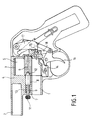
- Figure 1 shows a sectional view longitudinal with an auxiliary partial cut of a handgun according to the invention in the position of rest and including a stick and a trigger.
- Figure 2 is a partial sectional view of a handgun according to the invention comprising a handle as well as a pusher, in the last position preceding the shot.
- Figure 3 is an axial longitudinal section partial according to plan I-I of a munition according to the invention.
- Figure 4 is a cross section along the plan II-II of a munition according to the invention.
- the weapon handgun includes a projectile barrel 1 of neutralization and a barrel superior 2 blind, a rotary magazine 3 coming to be fixed on the weapon.
- the Canon ejection 1 is bored in the carcass 4 of the weapon and is located under the upper barrel 2, parallel to it and back from it.
- the upper barrel 2 constitutes a passive protuberance for the weapon.
- the rotary magazine 3 is a cylindrical monolithic part made of plastic with a circular front face and a circular rear face.
- Store 3 introduces itself externally like a barrel and has six rooms 5 cylindrical whose axes are parallel to its axis of rotation 6.
- Said chambers 5 dig right through share the monolithic piece and are arranged so that their circular sections are regularly spaced around a circle.
- each bedroom 5 is securely embedded by overmolding a cartridge having a neutralization projectile so that these cartridges cannot be removed with tools usual trade without damaging the magazine 3 in plastic.
- a parallel cylindrical channel 7 which comprises the part cylindrical 8 to 12 and a spring 13 ensuring the maintenance and centering the rotary magazine 3.
- the circular front face of the rotary magazine 3 has a conical recess in its center.
- the end conical 12 of the cylindrical part housed in the channel lying between the two barrels 1, 2 protrudes in the space of the carcass 4 reserved for the location of said magazine 3.
- the user To insert magazine 3 into the weapon, the user must remove the space reserved for the said magazine 3 the conical end 12 by translating by the head 11 the cylindrical part in its channel 7.
- the rotary magazine 3 has six rounded recesses arranged on its surface cylindrical external. One of these recesses in which penetrates the lobe of the part 14 is shown in section partial offset in Figure 1. These recesses are regularly spaced and are placed in the middle of two successive rooms. At rest, the rounded part of a piece 14 is inserted into one of the recesses of so that store 3 can no longer revolve around its axis of rotation 6. In FIG. 1, the part 14 partially inserted into one of the recesses belongs to a plane at the back of the plane chopped off.
- a striker 15 is positioned opposite the chamber which will be in continuity with the barrel ejection 1.
- a trigger 16 will trigger firing by operating a striking weight 17 striker 15.
- a rotation lever 18 will make turn the magazine 3 around its axis 6 during a pressure on trigger 16, this magazine behaving like a charged, non-refillable barrel.
- the user activates the rotary magazine 3 in plastic material fitted with cartridges in the space of the carcass 4 of the weapon reserved for this purpose. To do this, it proceeds as described above.
- part 14 is housed partially in one of the six peripheral recesses of magazine 3 so as to block it around its axis of rotation 6.
- This position of magazine 3 corresponds to aligning a chamber with the ejection barrel 1.
- Pressing the trigger 16 will generate a triple action: first, the part 14 blocking the magazine 3 goes pivot to release said magazine 3 about its axis of rotation 6. Then the rotation lever 18 is put in motion and will cause a rotation of one sixth of the magazine 3 around its axis 6 so as to bring the next chamber in front of the ejection barrel 1.
- the striking weight 17 of the striker 15 is moved until the percussion of the cartridge. Once fired, the user releases trigger 16 to its rest position. The weapon is again ready for a new shot. When all six cartridges have been used, the user removes the plastic magazine 3 and discards it. he can replace it with another full magazine.
- the handgun comprises a handle 20 including a linear magazine for cartridges and the constituent parts of the triggering mechanism for shooting, an elongated monobloc part 21 , a member 22 for triggering the firing and an ejection cannon 23 for the neutralization projectiles.
- the handle 20 is constituted by an elongated body slightly curved to facilitate good grip of the weapon with the hand, and has an upper part including the pusher 22 and a lower part comprising the ejection barrel 23.
- Said upper part is connected to said lower part by means of an elongated monobloc piece 21 starting at the end of the upper part located beyond the pusher 22 and ending on the external lateral surface 24 of the barrel 23.
- the one-piece elongated piece 21 has a straight segment 25 perpendicular to the axis of the barrel 23 and located in front of the mouth of said barrel 23 relative to the handle 20.
- the one-piece elongated piece 21 constitutes by this segment 25 a protuberance avoiding firing touching toe.
- the pusher 22 is an elongated piece having in particular a slightly curved front face 26 to prevent the finger which will actuate it from sliding, and a rounded rear recess 27. A pressure on the pusher 22 causes said pusher 22 to translate in a parallel direction to the axis of the barrel 23.
- the thin mixed lines in FIG. 2 materialize the position of the pusher 22 at rest.
- the rounded rear recess 27 of the pusher 22 receives the rounded part of a rotating elongated part 29 coming to bear against a part 30 secured to the striking weight 31.
- the translation of the pusher 22 will induce a linear displacement of the rounded part of the elongated part 29, said part 29 performing in at the same time a rotation around its axis.
- This rotation will in turn induce rotation of the counterweight 31 via the part 30 which is united.
- the rotating elongated part 29 ends up losing contact with the counterweight 31 which immediately pivots around its axis in reverse, undergoing a brutal acceleration due to the push of a molten part 32 by a spring 33 which relaxes.
- the striker 34 being secured to the counterweight 31 strikes the cartridge in front of the barrel 23.
- the lines mixed fine in Figure 2 materialize said striker 34 in percussion position.
- the shop linear plastic material with cartridges equipped with their neutralization projectile is introduced into the weapon through an opening 28 located in the lower part of the handle 20. The store comes in abutment against a spring.
- the store With each shot, via a lever (not shown) whose end is housed in the groove 35, the store is translated to the outside of the handle 20 of a length corresponding to the spacing between two successive cartridges from the store.
- ammunition according to the invention is constituted by a rotary magazine 41 comprising six identical cylindrical chambers 36, parallel to each other, evenly distributed around a circle and each intended to house a cartridge.
- a cartridge consists of a deformable projectile 38, a powder charge 39 and a primer 40, these three elements being separable. More precisely, each chamber 36 has an enlarged upstream bore 37 in which is embedded the deformable projectile 38 and a downstream bore into which the load of powder 39 used for propelling the projectile 38, and the primer 40.
- the axes of the downstream and upstream bores are not not in line with each other, because the bore 37 intended to receive the deformable projectile 38 was machined not only to receive said projectile 38 but also to provide a thickness e between each bore 37 and the outer wall 42 of the barrel 41 having to resist the ejection pressure of a projectile deformable 38 and may break if another type of projectile was engaged in room 36.
- the powder propellant 39 consists of 5 centigrams of a simple basic fine powder, based on nitrocellulose, manufactured by SNPE and primer 40 is standard to central percussion.
- the projectile deformable 38 In the absence of any constraint the projectile deformable 38 has a substantially spherical shape, the projectile acquiring a substantially cylindrical shape with two rounded ends when it is housed in the bore 37.
- the body of the rotary magazine 41 is produced from a barrel, made up of a material plastic loaded with solid particles and more specifically short glass fibers, this barrel being rigid and undeformable.
- the deformable projectile 38 which is made of polyurethane and which has a diameter initial 13mm when free has the capacity to crash on impact in the form of a 35mm wafer about diameter. Indeed, the deformed projectile 38 in barrel 41 instantly resumes a shape spherical as soon as it is expelled from the barrel of the weapon and substantially in the form of a flexible ball to the impact.
- the first step is to define the structural features and dimensions of the empty barrel 41 so as to adapt it to the weapon on which it will be mounted.
- the second step is to also determine as finely as possible the characteristics of the couple primer 40 / propellant powder charge 39 to allow the expulsion of the deformable projectile 38 without damaging nor modify the barrel 41 while communicating to the said projectile sufficient emission speed.
- the modification of one of the characteristics of the barrel 41 loaded with cartridges would cause operation erratic self defense weapon. Indeed, the substitution for example of a deformable projectile 38 by a heavier projectile could lead to the bursting of the barrel 41. Consequently, the risk to transform a self-defense weapon into a weapon lethal offensive is negligible.
- the rotary magazine 41 is used as a standard barrel of revolver. Indeed, after having placed the barrel 41 on its axis of rotation in the carcass of the weapon, a full pressure on the trigger first causes the cocking of the dog then the percussion of the primer followed by the ignition of the propellant powder and finally the expulsion of the deformable projectile 38. To fire the other projectiles 38 of the barrel 41, it is necessary to renew the operation, this non-refillable rotary magazine being thrown after firing all the cartridges and a new one rotary magazine being placed in the weapon.
Landscapes
- Engineering & Computer Science (AREA)
- General Engineering & Computer Science (AREA)
- Toys (AREA)
- Emergency Lowering Means (AREA)
- Aiming, Guidance, Guns With A Light Source, Armor, Camouflage, And Targets (AREA)
Abstract
Description
Contrairement aux autres moyens de défense rapprochée en vigueur sur le marché comme les diffuseurs de gaz, ce type d'arme peut être utilisé à plusieurs mètres de l'agresseur permettant d'éviter le corps à corps.
La poignée 20 est constituée par un corps allongé légèrement incurvé pour faciliter une bonne préhension de l'arme avec la main, et possède une partie supérieure incluant le poussoir 22 et une partie inférieure comprenant le canon d'éjection 23.
La pièce allongée monobloc 21 présente un segment rectiligne 25 perpendiculaire à l'axe du canon 23 et situé en avant de la bouche dudit canon 23 par rapport à la poignée 20. La pièce allongée monobloc 21 constitue par ce segment 25 une protubérance évitant le tir à bout touchant. Le poussoir 22 est une pièce allongée possédant notamment une face avant 26 légèrement incurvée pour éviter au doigt qui va l'actionner de glisser, et un évidement arrière arrondi 27. Une pression sur le poussoir 22 entraíne une translation dudit poussoir 22 selon une direction parallèle à l'axe du canon 23. Les traits fins mixtes sur la figure 2 matérialisent la position du poussoir 22 au repos.
Claims (20)
- Arme de poing destinée à tirer des projectiles de neutralisation, et comprenant notamment un canon, caractérisée en ce que la bouche du canon d'éjection (1,23) est située en retrait d'une protubérance (2,25) solidaire de l'arme.
- Arme de poing selon la revendication 1 caractérisée en ce que la protubérance (2,25) ménage une distance d'au moins 30 millimètres entre la bouche du canon (1,23) et une cible venant en appui contre la protubérance (2,25).
- Arme de poing selon l'une des revendications 1 à 2 caractérisée en ce que la protubérance (2) est constituée par un cylindre alésé semblable à un canon de revolver.
- Arme de poing selon la revendication 1 caractérisée en ce que plusieurs cartouches contenant chacune un projectile de neutralisation peuvent être chargées dans l'arme.
- Arme de poing selon la revendication 4 caractérisée en ce que les cartouches sont logées dans une munition monolithique.
- Arme de poing selon la revendication 5 caractérisée en ce que la munition monolithique est un magasin rotatif (3, 41).
- Arme de poing selon l'une des revendications 5 ou 6 caractérisée en ce que les cartouches sont encastrées dans la munition monolithique de sorte qu'elles ne peuvent pas être extraites de ladite munition.
- Arme de poing selon l'une des revendications 1 ou 5 à 7 caractérisée en ce que les projectiles ont un diamètre supérieur ou égal à 11,6 mm.
- Arme de poing selon l'une des revendications 1 ou 4 caractérisée en ce que les projectiles sont déformables.
- Arme de poing selon l'une quelconque des revendications 1 à 3 caractérisée en ce que ladite arme a la forme d'un revolver, et comprend un canon supérieur apparent (2) constituant la protubérance, et un canon d'éjection (1) des projectiles de neutralisation, alésé dans la carcasse (4) de l'arme, et placé sous le canon supérieur (2) parallèlement à celui-ci et en retrait de celui-ci.
- Arme de poing selon l'une des revendications 1 ou 2, caractérisée en ce qu'elle comporte une poignée (20) qui est munie dans sa partie supérieure d'un organe pour déclencher le tir, et dont la partie inférieure comprend le canon d'éjection (23).
- Arme de poing selon la revendication 11, caractérisée en ce que l'organe pour déclencher le tir est un poussoir (22) qui coulisse en translation et déplace vers l'extérieur un magasin linéaire engagé dans une ouverture (28) située dans la partie inférieure de la poignée (20).
- Munition pour une arme de poing destinée à tirer des projectiles de neutralisation, caractérisée en ce qu'elle est monolithique et forme un magasin rotatif (3, 41) comportant plusieurs chambres (5, 36) recevant chacune une cartouche qui ne peut pas être extraite de ladite munition.
- Munition selon la revendication 13, caractérisée en ce que la paroi externe de la cartouche est constituée par au moins un alésage (37) du magasin rotatif (41).
- Munition selon l'une des revendications 13 ou 14, caractérisée en ce que chaque cartouche n'est constituée que par un projectile déformable (38), une charge de poudre (39) et une amorce (40).
- Munition selon la revendication 15, caractérisée en ce que, en l'absence de toute contrainte, le projectile se présente sensiblement sous la forme d'une sphère, ce projectile (38) devenant sensiblement cylindrique à bouts arrondis lorsqu'il est engagé dans le magasin rotatif (41).
- Munition selon la revendication 16, caractérisée en ce que le rapport des diamètres entre le projectile libre sous forme de sphère et l'alésage (37) du magasin rotatif (41) destiné à le recevoir est compris entre 1,2 et 1,7.
- Munition selon la revendication 17, caractérisée en ce que les alésages (37) du magasin rotatif (41) destinés à recevoir les projectiles (38) présentent un diamètre supérieur à 9,3mm.
- Munition selon la revendication 13, caractérisée en ce que le corps du magasin rotatif (41) est un barillet de revolver réalisé en matière plastique chargée de particules solides.
- Munition selon l'une des revendications 13 ou 14, caractérisée en ce que la paroi (e) entre chaque alésage (37) et la surface extérieure (42) du magasin rotatif (41) résiste à la pression d'éjection du projectile déformable (38) mais peut se rompre si un autre projectile est engagé dans l'alésage (37).
Priority Applications (1)
| Application Number | Priority Date | Filing Date | Title |
|---|---|---|---|
| EP01121513A EP1160532A3 (fr) | 1997-09-25 | 1998-09-24 | Magasin du type tambour comportant des munitions pour armes de neutralisation |
Applications Claiming Priority (2)
| Application Number | Priority Date | Filing Date | Title |
|---|---|---|---|
| FR9711941 | 1997-09-25 | ||
| FR9711941A FR2768805B1 (fr) | 1997-09-25 | 1997-09-25 | Arme de poing pour projectiles de neutralisation |
Related Child Applications (1)
| Application Number | Title | Priority Date | Filing Date |
|---|---|---|---|
| EP01121513A Division EP1160532A3 (fr) | 1997-09-25 | 1998-09-24 | Magasin du type tambour comportant des munitions pour armes de neutralisation |
Publications (2)
| Publication Number | Publication Date |
|---|---|
| EP0905469A1 true EP0905469A1 (fr) | 1999-03-31 |
| EP0905469B1 EP0905469B1 (fr) | 2002-07-03 |
Family
ID=9511469
Family Applications (2)
| Application Number | Title | Priority Date | Filing Date |
|---|---|---|---|
| EP19980402339 Expired - Lifetime EP0905469B1 (fr) | 1997-09-25 | 1998-09-24 | Arme de poing pour projectiles de neutralisation. |
| EP01121513A Withdrawn EP1160532A3 (fr) | 1997-09-25 | 1998-09-24 | Magasin du type tambour comportant des munitions pour armes de neutralisation |
Family Applications After (1)
| Application Number | Title | Priority Date | Filing Date |
|---|---|---|---|
| EP01121513A Withdrawn EP1160532A3 (fr) | 1997-09-25 | 1998-09-24 | Magasin du type tambour comportant des munitions pour armes de neutralisation |
Country Status (4)
| Country | Link |
|---|---|
| EP (2) | EP0905469B1 (fr) |
| DE (1) | DE69806317T2 (fr) |
| ES (1) | ES2179437T3 (fr) |
| FR (1) | FR2768805B1 (fr) |
Cited By (1)
| Publication number | Priority date | Publication date | Assignee | Title |
|---|---|---|---|---|
| FR2791421A1 (fr) | 1999-03-25 | 2000-09-29 | Humbert Ctts Sa | Arme de neutralisation a canon surdimensionne |
Citations (3)
| Publication number | Priority date | Publication date | Assignee | Title |
|---|---|---|---|---|
| US4083138A (en) * | 1976-12-13 | 1978-04-11 | Charles Cash | Close combat backup weapon |
| EP0149712A2 (fr) * | 1983-08-23 | 1985-07-31 | DeWitt, Clinton J. | Barillet à enclenchement pour revolver |
| FR2687217A1 (fr) * | 1992-02-11 | 1993-08-13 | Fn Engineerung Sa | Munition multiple et arme pour la mise en óoeuvre d'une telle munition. |
Family Cites Families (5)
| Publication number | Priority date | Publication date | Assignee | Title |
|---|---|---|---|---|
| US2830398A (en) * | 1956-06-04 | 1958-04-15 | Cassel D Hibbs | Ejector for ball and cap cylinder type revolver |
| US3765116A (en) * | 1971-01-07 | 1973-10-16 | Colt Ind Operating Corp | Cylinder for revolvers |
| FR2398280A1 (fr) * | 1977-07-20 | 1979-02-16 | Serat | Barillet perfectionne pour revolver |
| GB2225627B (en) * | 1988-10-25 | 1992-08-19 | Haley & Weller Ltd | Dye marking system |
| FR2669996B3 (fr) * | 1990-11-30 | 1993-11-05 | Verney Carron Sa | Projectile pour munitions d'armes a feu de gros calibre. |
-
1997
- 1997-09-25 FR FR9711941A patent/FR2768805B1/fr not_active Expired - Fee Related
-
1998
- 1998-09-24 EP EP19980402339 patent/EP0905469B1/fr not_active Expired - Lifetime
- 1998-09-24 DE DE1998606317 patent/DE69806317T2/de not_active Expired - Fee Related
- 1998-09-24 EP EP01121513A patent/EP1160532A3/fr not_active Withdrawn
- 1998-09-24 ES ES98402339T patent/ES2179437T3/es not_active Expired - Lifetime
Patent Citations (3)
| Publication number | Priority date | Publication date | Assignee | Title |
|---|---|---|---|---|
| US4083138A (en) * | 1976-12-13 | 1978-04-11 | Charles Cash | Close combat backup weapon |
| EP0149712A2 (fr) * | 1983-08-23 | 1985-07-31 | DeWitt, Clinton J. | Barillet à enclenchement pour revolver |
| FR2687217A1 (fr) * | 1992-02-11 | 1993-08-13 | Fn Engineerung Sa | Munition multiple et arme pour la mise en óoeuvre d'une telle munition. |
Cited By (1)
| Publication number | Priority date | Publication date | Assignee | Title |
|---|---|---|---|---|
| FR2791421A1 (fr) | 1999-03-25 | 2000-09-29 | Humbert Ctts Sa | Arme de neutralisation a canon surdimensionne |
Also Published As
| Publication number | Publication date |
|---|---|
| DE69806317T2 (de) | 2003-03-06 |
| FR2768805A1 (fr) | 1999-03-26 |
| ES2179437T3 (es) | 2003-01-16 |
| EP1160532A3 (fr) | 2002-05-02 |
| EP1160532A2 (fr) | 2001-12-05 |
| EP0905469B1 (fr) | 2002-07-03 |
| DE69806317D1 (de) | 2002-08-08 |
| FR2768805B1 (fr) | 1999-10-22 |
Similar Documents
| Publication | Publication Date | Title |
|---|---|---|
| CA2145950C (fr) | Projectile, notamment balle non letale | |
| EP0324688B1 (fr) | Arme d'épaule à usage de lance-roquette | |
| EP0106263A1 (fr) | Projectile explosif perforant encartouché | |
| WO1995034796A1 (fr) | Systeme d'arme a feu individuelle | |
| CH628422A5 (fr) | Subprojectile destine a etre expulse d'un projectile. | |
| EP0737298A1 (fr) | Balle de chasse a fleche telescopee, comportant un sous-projectile associe a un lanceur | |
| BE1016438A5 (fr) | Dispositif de tir. | |
| EP3504501B1 (fr) | Dispositif neutralisateur de son pour arme à feu | |
| EP0905469B1 (fr) | Arme de poing pour projectiles de neutralisation. | |
| FR2509457A1 (fr) | Projectile a trajectoire courte | |
| US7451563B1 (en) | 8-in-1 deluxe field loader | |
| EP0218489A2 (fr) | Arme à feu à bascule à double canon de gros calibre | |
| FR2687217A1 (fr) | Munition multiple et arme pour la mise en óoeuvre d'une telle munition. | |
| EP4291850B1 (fr) | Canon avec munition verrouillable | |
| EP0884553B1 (fr) | Ensemble de propulsion pour projectile limitant l'effort de recul | |
| EP2342526A1 (fr) | Mecanisme pneumatique pour arme-jouet lancant des billes de peinture ou de plastique de faible poids, actionne par une munition pyrotechnique specifique | |
| FR2954820A1 (fr) | Arme automatique sans recul ni relevement et munition telescopique | |
| BE1010259A5 (fr) | Systeme d'arme a feu; chargeur et fut pour un tel systeme. | |
| US8375931B2 (en) | Compressed gas operated firearm | |
| EP0069184A1 (fr) | Arme à feu pour tirer des cartouches auto-propulsives, cartouches auto-propulsives et procédé de fabrication | |
| FR2725268A1 (fr) | Lanceur de projectile, a canon consommable | |
| EP1438546B1 (fr) | Munition pour exercice de tir | |
| FR2777987A1 (fr) | Arme d'epaule destinee a tirer des munitions a forte impulsion | |
| FR2791421A1 (fr) | Arme de neutralisation a canon surdimensionne | |
| EP2461129A1 (fr) | Dispositif de durcissement d'une liaison mecanique de propulseur pour munition de mortier et munition comportant une telle liaison |
Legal Events
| Date | Code | Title | Description |
|---|---|---|---|
| PUAI | Public reference made under article 153(3) epc to a published international application that has entered the european phase |
Free format text: ORIGINAL CODE: 0009012 |
|
| AK | Designated contracting states |
Kind code of ref document: A1 Designated state(s): BE DE ES FR GB IT |
|
| AX | Request for extension of the european patent |
Free format text: AL;LT;LV;MK;RO;SI |
|
| 17P | Request for examination filed |
Effective date: 19990423 |
|
| AKX | Designation fees paid |
Free format text: BE DE ES FR GB IT |
|
| 17Q | First examination report despatched |
Effective date: 20010523 |
|
| GRAG | Despatch of communication of intention to grant |
Free format text: ORIGINAL CODE: EPIDOS AGRA |
|
| GRAG | Despatch of communication of intention to grant |
Free format text: ORIGINAL CODE: EPIDOS AGRA |
|
| GRAH | Despatch of communication of intention to grant a patent |
Free format text: ORIGINAL CODE: EPIDOS IGRA |
|
| GRAH | Despatch of communication of intention to grant a patent |
Free format text: ORIGINAL CODE: EPIDOS IGRA |
|
| GRAA | (expected) grant |
Free format text: ORIGINAL CODE: 0009210 |
|
| AK | Designated contracting states |
Kind code of ref document: B1 Designated state(s): BE DE ES FR GB IT |
|
| REF | Corresponds to: |
Ref document number: 69806317 Country of ref document: DE Date of ref document: 20020808 |
|
| GBT | Gb: translation of ep patent filed (gb section 77(6)(a)/1977) |
Effective date: 20021007 |
|
| REG | Reference to a national code |
Ref country code: ES Ref legal event code: FG2A Ref document number: 2179437 Country of ref document: ES Kind code of ref document: T3 |
|
| PLBE | No opposition filed within time limit |
Free format text: ORIGINAL CODE: 0009261 |
|
| STAA | Information on the status of an ep patent application or granted ep patent |
Free format text: STATUS: NO OPPOSITION FILED WITHIN TIME LIMIT |
|
| 26N | No opposition filed |
Effective date: 20030404 |
|
| PGFP | Annual fee paid to national office [announced via postgrant information from national office to epo] |
Ref country code: DE Payment date: 20030908 Year of fee payment: 6 |
|
| PGFP | Annual fee paid to national office [announced via postgrant information from national office to epo] |
Ref country code: ES Payment date: 20030915 Year of fee payment: 6 |
|
| PGFP | Annual fee paid to national office [announced via postgrant information from national office to epo] |
Ref country code: GB Payment date: 20030916 Year of fee payment: 6 |
|
| PGFP | Annual fee paid to national office [announced via postgrant information from national office to epo] |
Ref country code: FR Payment date: 20030929 Year of fee payment: 6 |
|
| PGFP | Annual fee paid to national office [announced via postgrant information from national office to epo] |
Ref country code: BE Payment date: 20031010 Year of fee payment: 6 |
|
| PG25 | Lapsed in a contracting state [announced via postgrant information from national office to epo] |
Ref country code: GB Free format text: LAPSE BECAUSE OF NON-PAYMENT OF DUE FEES Effective date: 20040924 |
|
| PG25 | Lapsed in a contracting state [announced via postgrant information from national office to epo] |
Ref country code: ES Free format text: LAPSE BECAUSE OF NON-PAYMENT OF DUE FEES Effective date: 20040925 |
|
| PG25 | Lapsed in a contracting state [announced via postgrant information from national office to epo] |
Ref country code: BE Free format text: LAPSE BECAUSE OF NON-PAYMENT OF DUE FEES Effective date: 20040930 |
|
| BERE | Be: lapsed |
Owner name: *HUMBERT CTTS Effective date: 20040930 |
|
| PG25 | Lapsed in a contracting state [announced via postgrant information from national office to epo] |
Ref country code: DE Free format text: LAPSE BECAUSE OF NON-PAYMENT OF DUE FEES Effective date: 20050401 |
|
| GBPC | Gb: european patent ceased through non-payment of renewal fee |
Effective date: 20040924 |
|
| PG25 | Lapsed in a contracting state [announced via postgrant information from national office to epo] |
Ref country code: FR Free format text: LAPSE BECAUSE OF NON-PAYMENT OF DUE FEES Effective date: 20050531 |
|
| REG | Reference to a national code |
Ref country code: FR Ref legal event code: ST |
|
| PG25 | Lapsed in a contracting state [announced via postgrant information from national office to epo] |
Ref country code: IT Free format text: LAPSE BECAUSE OF NON-PAYMENT OF DUE FEES;WARNING: LAPSES OF ITALIAN PATENTS WITH EFFECTIVE DATE BEFORE 2007 MAY HAVE OCCURRED AT ANY TIME BEFORE 2007. THE CORRECT EFFECTIVE DATE MAY BE DIFFERENT FROM THE ONE RECORDED. Effective date: 20050924 |
|
| REG | Reference to a national code |
Ref country code: ES Ref legal event code: FD2A Effective date: 20040925 |
|
| BERE | Be: lapsed |
Owner name: *HUMBERT CTTS Effective date: 20040930 |