EP0905534A2 - Procédé de fixation de l'extrémité d'une fibre optique en verre dans un embout de connexion en verre - Google Patents
Procédé de fixation de l'extrémité d'une fibre optique en verre dans un embout de connexion en verre Download PDFInfo
- Publication number
- EP0905534A2 EP0905534A2 EP98116640A EP98116640A EP0905534A2 EP 0905534 A2 EP0905534 A2 EP 0905534A2 EP 98116640 A EP98116640 A EP 98116640A EP 98116640 A EP98116640 A EP 98116640A EP 0905534 A2 EP0905534 A2 EP 0905534A2
- Authority
- EP
- European Patent Office
- Prior art keywords
- optical fiber
- glass
- glass sleeve
- fiber end
- laser
- Prior art date
- Legal status (The legal status is an assumption and is not a legal conclusion. Google has not performed a legal analysis and makes no representation as to the accuracy of the status listed.)
- Granted
Links
Images
Classifications
-
- G—PHYSICS
- G02—OPTICS
- G02B—OPTICAL ELEMENTS, SYSTEMS OR APPARATUS
- G02B6/00—Light guides; Structural details of arrangements comprising light guides and other optical elements, e.g. couplings
- G02B6/24—Coupling light guides
- G02B6/36—Mechanical coupling means
- G02B6/38—Mechanical coupling means having fibre to fibre mating means
- G02B6/3807—Dismountable connectors, i.e. comprising plugs
- G02B6/3833—Details of mounting fibres in ferrules; Assembly methods; Manufacture
- G02B6/3863—Details of mounting fibres in ferrules; Assembly methods; Manufacture fabricated by using polishing techniques
-
- G—PHYSICS
- G02—OPTICS
- G02B—OPTICAL ELEMENTS, SYSTEMS OR APPARATUS
- G02B6/00—Light guides; Structural details of arrangements comprising light guides and other optical elements, e.g. couplings
- G02B6/24—Coupling light guides
- G02B6/36—Mechanical coupling means
- G02B6/38—Mechanical coupling means having fibre to fibre mating means
- G02B6/3807—Dismountable connectors, i.e. comprising plugs
- G02B6/3833—Details of mounting fibres in ferrules; Assembly methods; Manufacture
- G02B6/3855—Details of mounting fibres in ferrules; Assembly methods; Manufacture characterised by the method of anchoring or fixing the fibre within the ferrule
Definitions
- the invention relates to a method for fastening a Leitleitmaschineendes aud glass in a glass sleeve, the Optical fiber end up to a defined position in the Glass sleeve is inserted.
- JP 58-108508 A it is known a fiber end in to fix a sleeve by placing both against an end face is pushed. The fiber then temporarily becomes the core fixed. The fiber end is heated and thereby cleaned and smoothed, after which the fiber is glued to the sleeve becomes.
- Optical fiber end made of glass with a glass sleeve of a heat treatment process to merge is particularly simple and inexpensive Optical fiber end made of glass with a glass sleeve of a heat treatment process to merge.
- a such a method can be done, for example, using a laser but also with the help of an electric arc or a flame.
- corresponding Optics used that guarantee the maximum Intensity of the laser beam is distributed on a ring and thereby the outer area of the jacket of the Optical fiber and the inner area of the glass sleeve is melted and thereby joined together. It is especially important that the maximum intensity is not in the Center of the optical fiber end is applied because otherwise a deformation of the core would be possible.
- the method proposed according to the invention is also particularly advantageous as a cut or broken Optical fiber can be used. It is not the optical fiber is necessary before attaching it the glass sleeve, for example by mechanical polishing to edit. Cutting the optical fiber end can either by mechanical means or by means of a laser respectively.
- Either optical means such as a Hologram or an optical lens system are used, around the maximum intensity of the laser towards a ring distribute, but it is also possible to do this through a appropriate system to achieve the laser beam over the face of the glass sleeve and optical fiber end emotional.
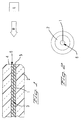
- FIG. 1 shows one Cross section through an optical fiber end in a glass sleeve
- FIG. 2 shows a top view of the end face of the glass sleeve with inserted light fiber end.
- Figure 1 shows a cross section through a Optical fiber end 1, which is made of glass, and through a glass sleeve 2.
- the glass sleeve 2 has a concentric bore in which the Optical fiber end is located.
- FIG. 1 shows the state that the end face 5 the optical fiber 1 and the end face 4 of the glass sleeve to match.
- the laser light is now introduced in such a way that in an area 6, which can also be seen in FIG. 2 is the highest intensity of light is applied.
Landscapes
- Physics & Mathematics (AREA)
- General Physics & Mathematics (AREA)
- Optics & Photonics (AREA)
- Mechanical Coupling Of Light Guides (AREA)
- Optical Couplings Of Light Guides (AREA)
Priority Applications (1)
| Application Number | Priority Date | Filing Date | Title |
|---|---|---|---|
| EP19980116640 EP0905534B1 (fr) | 1997-09-12 | 1998-09-03 | Procédé de fixation de l'extrémité d'une fibre optique en verre dans un embout de connexion en verre |
Applications Claiming Priority (3)
| Application Number | Priority Date | Filing Date | Title |
|---|---|---|---|
| EP97115903 | 1997-09-12 | ||
| EP97115903 | 1997-09-12 | ||
| EP19980116640 EP0905534B1 (fr) | 1997-09-12 | 1998-09-03 | Procédé de fixation de l'extrémité d'une fibre optique en verre dans un embout de connexion en verre |
Publications (3)
| Publication Number | Publication Date |
|---|---|
| EP0905534A2 true EP0905534A2 (fr) | 1999-03-31 |
| EP0905534A3 EP0905534A3 (fr) | 2000-05-03 |
| EP0905534B1 EP0905534B1 (fr) | 2003-11-05 |
Family
ID=26145774
Family Applications (1)
| Application Number | Title | Priority Date | Filing Date |
|---|---|---|---|
| EP19980116640 Expired - Lifetime EP0905534B1 (fr) | 1997-09-12 | 1998-09-03 | Procédé de fixation de l'extrémité d'une fibre optique en verre dans un embout de connexion en verre |
Country Status (1)
| Country | Link |
|---|---|
| EP (1) | EP0905534B1 (fr) |
Cited By (4)
| Publication number | Priority date | Publication date | Assignee | Title |
|---|---|---|---|---|
| WO2002050589A1 (fr) * | 2000-12-20 | 2002-06-27 | Euromicron Werkzeuge Gmbh | Optique de reproduction |
| DE10258481A1 (de) * | 2002-12-10 | 2004-07-08 | Lokys, Heinz-Jürgen, Dipl.-Ing. | Fiberoptisches Beleuchtungssystem und Verfahren zu dessen Herstellung |
| DE102018220477A1 (de) | 2018-11-28 | 2020-05-28 | Trumpf Laser Gmbh | Verfahren zum Laserschweißen einer Lichtleitfaser in einem Lochelement mittels eines UKP-Laserstrahls sowie zugehöriges optisches Element |
| US12240056B2 (en) | 2018-11-28 | 2025-03-04 | Trumpf Laser Gmbh | Ultrashort pulse laser butt welding |
Families Citing this family (2)
| Publication number | Priority date | Publication date | Assignee | Title |
|---|---|---|---|---|
| US8985866B2 (en) | 2012-06-20 | 2015-03-24 | Corning Cable Systems Llc | Simultaneous thermal forming of ferrule and optical fiber in a ferrule assembly to thermally form an optical surface in the ferrule assembly, and related fiber optic components, fiber connectors, assemblies, and methods |
| DE202016104842U1 (de) | 2015-09-03 | 2016-11-28 | PT Photonic Tools GmbH | Kühlkörper für eine Steckerbindungs-Vorrichtung |
Family Cites Families (4)
| Publication number | Priority date | Publication date | Assignee | Title |
|---|---|---|---|---|
| JPS5910918A (ja) * | 1982-07-12 | 1984-01-20 | Nippon Telegr & Teleph Corp <Ntt> | 光フアイバコネクタプラグの製造方法 |
| JPS5962812A (ja) * | 1982-10-04 | 1984-04-10 | Nippon Telegr & Teleph Corp <Ntt> | 光フアイバコネクタ中子 |
| JPS63183407A (ja) * | 1987-01-27 | 1988-07-28 | Fujitsu Ltd | 光フアイバの端末固定構造 |
| US5500917A (en) * | 1994-04-18 | 1996-03-19 | Gould Electronics Inc. | Optical assembly/housing for securing optical fiber components, devices and fibers to the same or to mounting fixtures |
-
1998
- 1998-09-03 EP EP19980116640 patent/EP0905534B1/fr not_active Expired - Lifetime
Cited By (8)
| Publication number | Priority date | Publication date | Assignee | Title |
|---|---|---|---|---|
| WO2002050589A1 (fr) * | 2000-12-20 | 2002-06-27 | Euromicron Werkzeuge Gmbh | Optique de reproduction |
| US6980364B2 (en) | 2000-12-20 | 2005-12-27 | Euromicron Werkzeuge Gmbh | Projector lens |
| DE10258481A1 (de) * | 2002-12-10 | 2004-07-08 | Lokys, Heinz-Jürgen, Dipl.-Ing. | Fiberoptisches Beleuchtungssystem und Verfahren zu dessen Herstellung |
| DE10258481B4 (de) * | 2002-12-10 | 2009-01-29 | Lokys, Heinz-Jürgen, Dipl.-Ing. | Fiberoptisches Beleuchtungssystem und Verfahren zu dessen Herstellung |
| DE102018220477A1 (de) | 2018-11-28 | 2020-05-28 | Trumpf Laser Gmbh | Verfahren zum Laserschweißen einer Lichtleitfaser in einem Lochelement mittels eines UKP-Laserstrahls sowie zugehöriges optisches Element |
| WO2020109029A1 (fr) | 2018-11-28 | 2020-06-04 | Trumpf Laser Gmbh | Procédé de soudage laser d'une fibre optique dans un élément perforé au moyen d'un faisceau laser à impulsions ultra-brèves et élément optique associé |
| US11573379B2 (en) | 2018-11-28 | 2023-02-07 | Trumpf Laser Gmbh | Laser welding of optical fibers in perforated elements and associated optical elements |
| US12240056B2 (en) | 2018-11-28 | 2025-03-04 | Trumpf Laser Gmbh | Ultrashort pulse laser butt welding |
Also Published As
| Publication number | Publication date |
|---|---|
| EP0905534A3 (fr) | 2000-05-03 |
| EP0905534B1 (fr) | 2003-11-05 |
Similar Documents
| Publication | Publication Date | Title |
|---|---|---|
| DE69925152T2 (de) | Benutzung eines Lasers zum Fusionsspleißen optischer Komponenten mit sehr unterschiedlichem Querschnitt | |
| EP0191328B1 (fr) | Module opto-électronique | |
| DE69015927T2 (de) | Vorrichtung und Verfahren für die Herstellung von permanenten faseroptischen Spleissen niedriger Dämpfung. | |
| DE69321346T2 (de) | Stecker ohne klebstoff für optische fasern | |
| DE3587943T2 (de) | Verbinder für Hochleistungsstrahl. | |
| DE69414951T2 (de) | Verbindung von körpern aus kunstoffmaterial | |
| DE69109317T2 (de) | Verfahren zur Herstellung eines optischen Kopplers. | |
| DE69628120T2 (de) | Befestigung von Stützelementen an Intraokularlinsen unter Verwendung eines Diodenlasers | |
| DE2314753B2 (de) | Verfahren und Vorrichtung zum Verbinden optischer Fasern | |
| DE19823934A1 (de) | Vorrichtung zum Koppeln einer Lichtquelle mit einer Lichtleitfaser | |
| DE102007034261B4 (de) | Vorrichtung zum Vereinigen einzelner Lichtstrahlen verschiedener Wellenlängen zu einem koaxialen Lichtbündel | |
| DE112007002109T5 (de) | Wellenleiter für Kunststoffschweißen unter Verwendung einer inkohärenten Infrarot-Lichtquelle | |
| DE2921035C2 (de) | Optisches Verzweigerelement | |
| DE10327256B4 (de) | Strahlkombinierer | |
| DE3245229C2 (fr) | ||
| EP0905534B1 (fr) | Procédé de fixation de l'extrémité d'une fibre optique en verre dans un embout de connexion en verre | |
| DE2623295A1 (de) | Kupplung fuer zwei nachrichtenuebertragungs-lichtleiter | |
| DE2640422A1 (de) | Verfahren und vorrichtung zum verbinden von lichtleitfasern | |
| DE19948372C2 (de) | Faseroptisches Sende-Bauelement mit präzise einstellbarer Einkopplung | |
| DE10127331B4 (de) | Verfahren zum Verbinden mindestens einer optischen Faser mit einer GRIN-Linse und Filtermodul | |
| DE10033785C2 (de) | Vorrichtung zum Einkoppeln von Laserstrahlen in eine Lichtleitfaser | |
| DE19839343A1 (de) | Verfahren zum Bearbeiten eines Bauteils oder einer Bauteilanordnung mittels elektromagnetischer Strahlung sowie Vorrichtung zum Fügen, insbesondere Verlöten | |
| DE69416714T2 (de) | Verfahren zum thermischen Verspleissen von optischen Fasern | |
| DE19840935B4 (de) | Abschlußstück für Lichtleitfasern | |
| DE3407413C2 (fr) |
Legal Events
| Date | Code | Title | Description |
|---|---|---|---|
| PUAI | Public reference made under article 153(3) epc to a published international application that has entered the european phase |
Free format text: ORIGINAL CODE: 0009012 |
|
| AK | Designated contracting states |
Kind code of ref document: A2 Designated state(s): AT BE CH DE DK ES FI FR GB GR IE IT LI NL PT SE |
|
| AX | Request for extension of the european patent |
Free format text: AL;LT;LV;MK;RO;SI |
|
| PUAL | Search report despatched |
Free format text: ORIGINAL CODE: 0009013 |
|
| AK | Designated contracting states |
Kind code of ref document: A3 Designated state(s): AT BE CH CY DE DK ES FI FR GB GR IE IT LI LU MC NL PT SE |
|
| AX | Request for extension of the european patent |
Free format text: AL;LT;LV;MK;RO;SI |
|
| 17P | Request for examination filed |
Effective date: 20001030 |
|
| AKX | Designation fees paid |
Free format text: AT BE CH DE DK ES FI FR GB GR IE IT LI NL PT SE |
|
| 17Q | First examination report despatched |
Effective date: 20010215 |
|
| GRAH | Despatch of communication of intention to grant a patent |
Free format text: ORIGINAL CODE: EPIDOS IGRA |
|
| RBV | Designated contracting states (corrected) |
Designated state(s): DE FR GB |
|
| GRAS | Grant fee paid |
Free format text: ORIGINAL CODE: EPIDOSNIGR3 |
|
| GRAA | (expected) grant |
Free format text: ORIGINAL CODE: 0009210 |
|
| AK | Designated contracting states |
Kind code of ref document: B1 Designated state(s): DE FR GB |
|
| REG | Reference to a national code |
Ref country code: GB Ref legal event code: FG4D Free format text: NOT ENGLISH |
|
| GBT | Gb: translation of ep patent filed (gb section 77(6)(a)/1977) |
Effective date: 20031107 |
|
| REF | Corresponds to: |
Ref document number: 59810070 Country of ref document: DE Date of ref document: 20031211 Kind code of ref document: P |
|
| REG | Reference to a national code |
Ref country code: IE Ref legal event code: FG4D Free format text: GERMAN |
|
| ET | Fr: translation filed | ||
| REG | Reference to a national code |
Ref country code: IE Ref legal event code: FD4D |
|
| PLBE | No opposition filed within time limit |
Free format text: ORIGINAL CODE: 0009261 |
|
| STAA | Information on the status of an ep patent application or granted ep patent |
Free format text: STATUS: NO OPPOSITION FILED WITHIN TIME LIMIT |
|
| 26N | No opposition filed |
Effective date: 20040806 |
|
| REG | Reference to a national code |
Ref country code: FR Ref legal event code: PLFP Year of fee payment: 19 |
|
| REG | Reference to a national code |
Ref country code: FR Ref legal event code: PLFP Year of fee payment: 20 |
|
| PGFP | Annual fee paid to national office [announced via postgrant information from national office to epo] |
Ref country code: FR Payment date: 20170925 Year of fee payment: 20 Ref country code: GB Payment date: 20170927 Year of fee payment: 20 |
|
| PGFP | Annual fee paid to national office [announced via postgrant information from national office to epo] |
Ref country code: DE Payment date: 20170927 Year of fee payment: 20 |
|
| REG | Reference to a national code |
Ref country code: DE Ref legal event code: R071 Ref document number: 59810070 Country of ref document: DE |
|
| REG | Reference to a national code |
Ref country code: GB Ref legal event code: PE20 Expiry date: 20180902 |
|
| PG25 | Lapsed in a contracting state [announced via postgrant information from national office to epo] |
Ref country code: GB Free format text: LAPSE BECAUSE OF EXPIRATION OF PROTECTION Effective date: 20180902 |