EP0905574B1 - Feuchtigkeitskontrolle zur Beseitigung von Blattwellungen - Google Patents
Feuchtigkeitskontrolle zur Beseitigung von Blattwellungen Download PDFInfo
- Publication number
- EP0905574B1 EP0905574B1 EP98307479A EP98307479A EP0905574B1 EP 0905574 B1 EP0905574 B1 EP 0905574B1 EP 98307479 A EP98307479 A EP 98307479A EP 98307479 A EP98307479 A EP 98307479A EP 0905574 B1 EP0905574 B1 EP 0905574B1
- Authority
- EP
- European Patent Office
- Prior art keywords
- sheet
- pair
- rolls
- moisture
- toner
- Prior art date
- Legal status (The legal status is an assumption and is not a legal conclusion. Google has not performed a legal analysis and makes no representation as to the accuracy of the status listed.)
- Expired - Lifetime
Links
- 238000012546 transfer Methods 0.000 claims description 39
- 239000012530 fluid Substances 0.000 claims description 6
- 239000000080 wetting agent Substances 0.000 claims description 6
- 230000003750 conditioning effect Effects 0.000 claims description 4
- 230000015572 biosynthetic process Effects 0.000 claims description 3
- 239000011248 coating agent Substances 0.000 claims description 2
- 238000000576 coating method Methods 0.000 claims description 2
- 238000009736 wetting Methods 0.000 claims description 2
- 108091008695 photoreceptors Proteins 0.000 description 14
- 239000000463 material Substances 0.000 description 13
- 238000000034 method Methods 0.000 description 9
- 239000000758 substrate Substances 0.000 description 9
- 239000002245 particle Substances 0.000 description 8
- 239000000843 powder Substances 0.000 description 8
- 238000011161 development Methods 0.000 description 7
- XLYOFNOQVPJJNP-UHFFFAOYSA-N water Substances O XLYOFNOQVPJJNP-UHFFFAOYSA-N 0.000 description 7
- 238000003384 imaging method Methods 0.000 description 6
- 238000000926 separation method Methods 0.000 description 3
- 238000004140 cleaning Methods 0.000 description 2
- 239000002131 composite material Substances 0.000 description 2
- 230000008602 contraction Effects 0.000 description 2
- 230000007613 environmental effect Effects 0.000 description 2
- 239000008187 granular material Substances 0.000 description 2
- 230000009191 jumping Effects 0.000 description 2
- SETQYEOWBPZUAW-UHFFFAOYSA-N 2-(4-benzhydrylpiperazin-1-yl)ethyl 5-(4,6-dimethyl-2-oxo-1,3,2$l^{5}-dioxaphosphinan-2-yl)-2,6-dimethyl-4-(3-nitrophenyl)-1,4-dihydropyridine-3-carboxylate Chemical compound O1C(C)CC(C)OP1(=O)C1=C(C)NC(C)=C(C(=O)OCCN2CCN(CC2)C(C=2C=CC=CC=2)C=2C=CC=CC=2)C1C1=CC=CC([N+]([O-])=O)=C1 SETQYEOWBPZUAW-UHFFFAOYSA-N 0.000 description 1
- 238000013459 approach Methods 0.000 description 1
- 238000003491 array Methods 0.000 description 1
- 239000000470 constituent Substances 0.000 description 1
- 238000010586 diagram Methods 0.000 description 1
- 238000007599 discharging Methods 0.000 description 1
- 230000000694 effects Effects 0.000 description 1
- 238000011067 equilibration Methods 0.000 description 1
- 239000000835 fiber Substances 0.000 description 1
- 230000009477 glass transition Effects 0.000 description 1
- 238000010348 incorporation Methods 0.000 description 1
- 150000002500 ions Chemical class 0.000 description 1
- 239000011159 matrix material Substances 0.000 description 1
- 230000003020 moisturizing effect Effects 0.000 description 1
- 239000011148 porous material Substances 0.000 description 1
- 238000007711 solidification Methods 0.000 description 1
- 230000008023 solidification Effects 0.000 description 1
- 239000007921 spray Substances 0.000 description 1
Images
Classifications
-
- G—PHYSICS
- G03—PHOTOGRAPHY; CINEMATOGRAPHY; ANALOGOUS TECHNIQUES USING WAVES OTHER THAN OPTICAL WAVES; ELECTROGRAPHY; HOLOGRAPHY
- G03G—ELECTROGRAPHY; ELECTROPHOTOGRAPHY; MAGNETOGRAPHY
- G03G15/00—Apparatus for electrographic processes using a charge pattern
- G03G15/65—Apparatus which relate to the handling of copy material
- G03G15/6555—Handling of sheet copy material taking place in a specific part of the copy material feeding path
- G03G15/6573—Feeding path after the fixing point and up to the discharge tray or the finisher, e.g. special treatment of copy material to compensate for effects from the fixing
- G03G15/6576—Decurling of sheet material
-
- G—PHYSICS
- G03—PHOTOGRAPHY; CINEMATOGRAPHY; ANALOGOUS TECHNIQUES USING WAVES OTHER THAN OPTICAL WAVES; ELECTROGRAPHY; HOLOGRAPHY
- G03G—ELECTROGRAPHY; ELECTROPHOTOGRAPHY; MAGNETOGRAPHY
- G03G2215/00—Apparatus for electrophotographic processes
- G03G2215/00362—Apparatus for electrophotographic processes relating to the copy medium handling
- G03G2215/00535—Stable handling of copy medium
- G03G2215/00662—Decurling device
-
- G—PHYSICS
- G03—PHOTOGRAPHY; CINEMATOGRAPHY; ANALOGOUS TECHNIQUES USING WAVES OTHER THAN OPTICAL WAVES; ELECTROGRAPHY; HOLOGRAPHY
- G03G—ELECTROGRAPHY; ELECTROPHOTOGRAPHY; MAGNETOGRAPHY
- G03G2215/00—Apparatus for electrophotographic processes
- G03G2215/00362—Apparatus for electrophotographic processes relating to the copy medium handling
- G03G2215/00535—Stable handling of copy medium
- G03G2215/0067—Damping device
Definitions
- This invention relates generally to a substrate conditioning device for an electrophotographic printing machine and, more particularly, concerns a moisture control system that applies moisture to cut sheets in a full color process printing machine such that sheets reach equilibrium in a relatively uncurled or flat state.
- a photoconductive member is charged to a substantially uniform potential so as to sensitize the surface thereof.
- the charged portion of the photoconductive member is exposed to a light image of an original document being reproduced. Exposure of the charged photoconductive member selectively dissipates the charges thereon in the irradiated areas.
- the latent image is developed by bringing a developer material into contact therewith.
- the developer material comprises toner particles adhering triboelectrically to carrier granules.
- the toner particles are attracted from the carrier granules to the latent image forming a toner powder image on the photoconductive member.
- the toner powder image is then transferred from the photoconductive member to a copy sheet.
- the toner particles are heated to permanently affix the powder image to the copy sheet.
- the foregoing generally describes a typical black and white electrophotographic printing machine.
- an architecture which comprises a plurality of image forming stations.
- One example of the plural image forming station architecture utilizes an image-on-image (IOI) system in which the photoreceptive member is recharged, reimaged and developed for each color separation.
- IIOI image-on-image
- This charging, imaging, developing and recharging, reimaging and developing, all followed by transfer to paper is done in a single revolution of the photoreceptor in so-called single pass machines, while multipass architectures form each color separation with a single charge, image and develop, with separate transfer operations for each color.
- the single pass architecture offers a potential for high throughput.
- US-A-3,647,525 controls the speed of the moisture transfer roller.
- US-A-4,652,110 attempts to replenish moisture lost in the fixing process by collecting moisture as it is driven off the copy sheet for reapplication to the sheet at a later time.
- US-A-5,434,029 describes an apparatus and method of preventing the curling of a substrate having toner images electrostatically adhered thereto which substrate has been subjected to heat for the purpose of fixing the toner images to the substrate. Simultaneous constraint of the copy substrate and the application of moisture thereto is effected by passing the substrate through the nip formed by two pressure engaged rollers, one of which is utilized for applying the water to the back side of the substrate as the substrate passes through the aftermentioned nip.
- US-A-5,264,899 describes a system for adding moisture to a copy sheet.
- the toner fixation step of electrostatographic reproduction desiccates paper, which may lead to the formation a wave along the sheet edge.
- EP-A-0862091 which forms part of the state of the art under Article 54(3), discloses the use of metering rolls contacting counter rotating transfer rolls to supply moisture to copy sheets as a function of the relative velocity between the copy sheets and transfer roll.
- the invention consists in a system that adds moisture to copy sheets while en route in a copier/printer, to control curl, comprising:
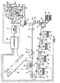
- This embodiment relates to an imaging system which is used to produce color output in a single revolution or pass of a photoreceptor belt but it is also useable with a multiple pass color process system, a single or multiple pass highlight color system and a black and white printing system.
- the printing machine 8 of the present invention uses a charge retentive surface in the form of an Active Matrix (AMAT) photoreceptor belt 10 supported for movement in the direction indicated by arrow 12, for advancing sequentially through the various xerographic process stations.
- the belt is entrained about a drive roller 14, tension roller 16 and fixed roller 18 and the roller 14 is operatively connected to a drive motor 20 for effecting movement of the belt through the xerographic stations.
- AMAT Active Matrix
- a portion of belt 10 passes through charging station A where a corona generating device, indicated generally by the reference numeral 22, charges the photoconductive surface of belt 10 to a relatively high, substantially uniform, preferably negative potential.
- a controller receives the image signals representing the desired output image and processes these signals to convert them to the various color separations of the image which is transmitted to a laser based output scanning device 24 which causes the charge retentive surface to be discharged in accordance with the output from the scanning device.
- the scanning device is a laser Raster Output Scanner (ROS).
- ROS Raster Output Scanner
- the ROS could be replaced by other xerographic exposure devices such as LED arrays.
- the photoreceptor which is initially charged to a voltage V 0 , undergoes dark decay to a level V ddp equal to about -500 volts. When exposed at the exposure station B it is discharged to V expose equal to about -50 volts. Thus after exposure, the photoreceptor contains a monopolar voltage profile of high and low voltages, the former corresponding to charged areas and the latter corresponding to discharged or background areas.
- developer structure indicated generally by the reference numeral 42 utilizing a hybrid jumping development (HJD) system
- the development roll is powered by two development fields (potentials across an air gap).
- the first field is the ac jumping field which is used for toner cloud generation.
- the second field is the dc development field which is used to control the amount of developed toner mass on the photoreceptor.
- the toner cloud causes charged toner particles to be attracted to the electrostatic latent image.
- Appropriate developer biasing is accomplished via a power supply.
- This type of system is a non-contact type in which only toner particles (black, for example) are attracted to the latent image and there is no mechanical contact between the photoreceptor and a toner delivery device to disturb a previously developed, but unfixed, image.
- a corona recharge device 36 having a high output current vs. control surface voltage (I/V) characteristic slope is employed for raising the voltage level of both the toned and untoned areas on the photoreceptor to a substantially uniform level.
- the recharging device 36 serves to recharge the photoreceptor to a predetermined level.
- a second exposure/imaging device 38 which comprises a laser based output structure is utilized for selectively discharging the photoreceptor on toned areas and/or bare areas, pursuant to the image to be developed with the second color toner.
- the photoreceptor contains toned and untoned areas at relatively high voltage levels and toned and untoned areas at relatively low voltage levels. These low voltage areas represent image areas which are developed using discharged area development (DAD).
- DAD discharged area development
- a negatively charged, developer material 40 comprising color toner is employed.
- the toner which by way of example may be yellow, is contained in a developer housing structure 42 disposed at a second developer station D and is presented to the latent images on the photoreceptor by way of a second HSD developer system.
- a power supply (not shown) serves to electrically bias the developer structure to a level effective to develop the discharged image areas with negatively charged yellow toner particles 40.
- a negative pre-transfer dicorotron member 50 is provided to condition the toner for effective transfer to a substrate using positive corona discharge.
- a sheet of support material 52 is moved either tray 80 or 81 into contact with the toner images at transfer station G.
- the sheet of support material is advanced to transfer station G by conventional sheet feeding apparatus, not shown.
- the sheet feeding apparatus includes a feed roll contacting the uppermost sheet of a stack copy sheets. The feed rolls rotate so as to advance the uppermost sheet from stack into a chute which directs the advancing sheet of support material into contact with photoconductive surface of belt 10 in a timed sequence so that the toner powder image developed thereon contacts the advancing sheet of support material at transfer station G.
- Transfer station G includes a transfer dicorotron 54 which sprays positive ions onto the backside of sheet 52. This attracts the negatively charged toner powder images from the belt 10 to sheet 52.
- a detack dicorotron 56 is provided for facilitating stripping of the sheets from the belt 10.
- Fusing station H includes a fuser assembly, indicated generally by the reference numeral 60, which permanently affixes the transferred powder image to sheet 52.
- fuser assembly 60 comprises a heated fuser roller 62 and a backup or pressure roller 64.
- Sheet 52 passes between fuser roller 62 and backup roller 64 with the toner powder image contacting fuser roller 62. In this manner, the toner powder images are permanently affixed to sheet 52.
- a chute guides the advancing sheets 52 to a catch tray, not shown, for subsequent removal from the printing machine by the operator.
- the residual toner particles carried by the non-image areas on the photoconductive surface are removed therefrom. These particles are removed at cleaning station I using a cleaning brush structure contained in a housing 66.
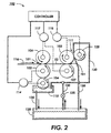
- the sheet conditioning device has transfer rollers 102 and 103 which are contacted by the lead edge of incoming sheets 52 as the sheets enter the nip area 101.
- Transfer rollers 102 and 103 are fixed as are metering rollers 104 and 105 that are in nip forming contact with transfer rollers 102 and 103, respectively.
- Back-up rollers 106 and 107 are driven by motor 117 and form a nip 101 with transfer rollers 102 and 103, respectively, while paper is present.
- Metering roller 104 is positioned with a portion thereof situated within an open part of fluid pan 110.
- Metering roller 105 is positioned in contact with transfer roller 103 to form a fluid reservoir in the nip 111. End seals (not shown) retain the fluid in said reservoir.
- Servo motors 114 and 115 are connected to transfer and metering rollers 102 and 104, and 103 and 105 respectively, and are adapted to drive the transfer rolls in the opposite direction to the paper travel through the paper path 116 and thereby controlling the amount of fluid applied to each surface.
- the wetting agent in this case water, is distributed to the metering rolls 104 and 105 from a pan and reservoir 110, 111, respectively, by way of sump 120, pump 125, and hoses 130. It should be understood that transfer rollers 102 and 103, as well as, metering rollers 104 and 105 could be made to articulate up and down to open and close nips with the back-up rollers 106 and 107, if desired.
- Some variables which affect how much moisture needs to be added for a sheet to rapidly reach equilibrium in an uncurled condition after fusing are: fuser and pressure roll temperature (affects moisture loss in the fuser); dwell time; initial sheet moisture content while in the feeder tray (will determine post fuser sheet moisture content); pre-fuser sheet temperature (will determine temperature rise and, therefore, moisture loss in the fuser); room relative humidity and temperature (determines equilibration relative humidity); wire or felt side being imaged (determines moisturization rate); sheet characteristics, such as, sheet basis weight, density, thickness, percent of moisture change as a function of fuser temperature, initial percent moisture, etc. (determines amount of moisture loss in the fuser).
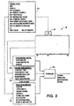
- Machine 8 in FIG. 3, in accordance with the present invention, is equipped with conventional temperature and humidity sensors to monitor machine characteristics as shown in block 94, environmental conditions as depicted in block 93, and a look-up table at block 95 that includes various paper characteristics.
- a user interface (UI) 91 allows an operator to inform the machine of the type of paper used as shown in block 92 which in turn sends a signal for incorporation into look-up table 95.
- Output signals from all three sources (93, 94 and 95) go to a controller 90 which uses appropriate conventional algorithms to adjust the amount of moisture added to each side of a sheet as it exits the fuser.
- controller 90 determines and adjusts the amount of water being transferred to each side of the sheet 52 by actuating servo motors 114 and 115 that are connected to transfer rolls 102 and 103 accordingly to either increase or decrease the speed of the transfer rollers in the opposite direction to the back-up rollers.
- V0 is a nominal speed equal to and in the opposite direction as the back-up roll speed
- a1 is a coefficient associated with paper stiffness
- a2 is a coefficient associated with basis weight
- a3 is associated with fuser temperature
- a4 is associated with wire or felt side
- a5 is associated with surface coating
- a6 is associated with image density, etc.
- the fuser roller or pressure roller temperature is high, more moisture needs to be added since more would be driven out in the fuser. If the paper stiffness is high, its beam strength will resist curling and less moisture needs to be added. If the image density is high, the imaged sheet will require more moisture to resist the effect of the increased toner mass.
Landscapes
- Physics & Mathematics (AREA)
- General Physics & Mathematics (AREA)
- Control Or Security For Electrophotography (AREA)
- Paper Feeding For Electrophotography (AREA)
- Fixing For Electrophotography (AREA)
- Electrostatic Charge, Transfer And Separation In Electrography (AREA)
Claims (7)
- System, das Kopierblättern beim Durchlaufen eines Kopierers/Druckers Feuchtigkeit hinzufügt, um Blattwellungen zu kontrollieren, umfassend:ein Paar von Andruckwalzen (106, 107) und ein Paar von gewöhnlich zylindrischen Transportwalzen (102, 103), die je eine äußere zylindrische Oberfläche aufweisen, wobei die Transportwalzen und die Andruckwalzen Walzenspalte (101) zwischen ihren äußeren zylindrischen Oberflächen definieren, wodurch die Kopierblätter transportiert werden;ein Paar von Dosierwalzen (104,105) mit einem daran verteilten Befeuchtungsmittel, wobei je eine des Paares von Dosierwalzen in Umfangsoberflächenberührung mit je einer der zylindrischen Transportwalzen (102, 103) in Berührung ist, um die äußeren Oberflächen der zylindrischen Transportwalzen (102, 103) zu befeuchten;ein Paar von Servomotoren (114, 115), wobei je einer der Servomotoren mit je einer der Transportwalzen (102, 103) verbunden ist, undeine Steuereinheit (100), die mit den Servomotoren verbunden ist, um die Geschwindigkeit der Servomotoren (114, 115) beim Antreiben des Paares von Transportwalzen (102, 103) in einer Richtung entgegengesetzt zu der Transportrichtung der Blätter an den Walzenspalten (101) zu steuern und dadurch die Menge an Befeuchtungsmittel, die auf jede Seite der Blätter aufgetragen wird, zu kontrollieren.
- System nach Anspruch 1, das ferner ein Paar von Behältern (110, 120) umfasst, wobei jeder des Paares von Behältern eine Menge an Befeuchtungsmittel speichert.
- System zum Fixieren eines Tonerbildes an einem Kopierblatt in einem elektrofotografischen System, um die Bildung von Wellungen in dem Körper des Blattes zu vermeiden, das umfasst.
eine erste und zweite Aufschmelzwalze (62, 64), die einen Walzenspalt dazwischen definieren, wobei wenigstens eine der Aufschmelzwalzen (62, 64) geheizt wird, wobei die Aufschmelzwalzen dazu dienen, ein Tonerbild auf einem durch den Walzenspalt transportierten Kopierblatt durch das Anwenden von Hitze und Druck auf das Kopierblatt zu fixieren, und ein Blattkonditionierungssystem nach Anspruch 1 oder 2. - System nach Anspruch 3, das ein Tablett zum Halten der Kopierblätter und Sensoren umfasst, die relative Feuchte des Tabletts, Raumtemperatur und relative Feuchte des Raumes abfühlen und Signale, die dieselben anzeigen, an die Steuereinheit (100) senden.
- System nach Anspruch 3 oder 4, das Eingaben in die Steuereinheit (100) einschließt, die Aufschmelzwalzentemperatur, Verweilzeit, Andruckwalzentemperatur und Befeuchtungsflüssigkeitseigenschaften kennzeichnen.
- System nach Anspruch 3, 4 oder 5, das eine Tabelle einschließt, die eine Eingabe von Blatteigenschaften, die Grundgewicht des Blattes, Blattdichte, Oberflächenbeschichtung, Dicke und Prozent der Feuchtigkeitsänderung als eine Funktion der Schmelzertemperatur und anfänglichen Prozentwert an Feuchtigkeit umfassen, für die Steuereinheit (100) bereitstellt.
- System nach Anspruch 3, 4, 5 oder 6, wobei die Steuereinheit (100) eingerichtet ist, die Geschwindigkeit der Servomotoren (114, 115) basierend auf Umgebungseingaben, Maschineneigenschaften, Papiereigenschaften und Bildtyp entweder zu erhöhen oder zu verringern.
Applications Claiming Priority (2)
| Application Number | Priority Date | Filing Date | Title |
|---|---|---|---|
| US940110 | 1997-09-29 | ||
| US08/940,110 US5842105A (en) | 1997-09-29 | 1997-09-29 | Controlled moisturization of paper to eliminate curl |
Publications (3)
| Publication Number | Publication Date |
|---|---|
| EP0905574A2 EP0905574A2 (de) | 1999-03-31 |
| EP0905574A3 EP0905574A3 (de) | 2000-05-24 |
| EP0905574B1 true EP0905574B1 (de) | 2003-07-09 |
Family
ID=25474248
Family Applications (1)
| Application Number | Title | Priority Date | Filing Date |
|---|---|---|---|
| EP98307479A Expired - Lifetime EP0905574B1 (de) | 1997-09-29 | 1998-09-15 | Feuchtigkeitskontrolle zur Beseitigung von Blattwellungen |
Country Status (4)
| Country | Link |
|---|---|
| US (1) | US5842105A (de) |
| EP (1) | EP0905574B1 (de) |
| JP (1) | JP4558853B2 (de) |
| DE (1) | DE69816212T2 (de) |
Families Citing this family (22)
| Publication number | Priority date | Publication date | Assignee | Title |
|---|---|---|---|---|
| US5987301A (en) * | 1997-09-29 | 1999-11-16 | Xerox Corporation | Paper conditioning system |
| US6011947A (en) * | 1997-09-29 | 2000-01-04 | Xerox Corporation | Apparatus and method for automatically adjusting water film thickness on conditioner metering rolls |
| JPH11216881A (ja) * | 1997-10-30 | 1999-08-10 | Xerox Corp | プリンタドライバの生成方法及びプリンタドライバを用いたカラープリントシステム |
| US5930578A (en) * | 1998-04-30 | 1999-07-27 | Xerox Corporation | Moisturizing rolls with end grooves for eliminating water spill from their ends |
| FI112684B (fi) * | 1999-03-23 | 2003-12-31 | Metso Paper Inc | Menetelmä paperi- tai kartonkirainan käyristymän mittaamiseksi ja säätämiseksi sekä paperi- tai kartonkikonelinja |
| US6052553A (en) * | 1999-05-27 | 2000-04-18 | Xerox Corporation | Post-fusing sheet conditioning apparatus |
| US6249667B1 (en) * | 2000-03-03 | 2001-06-19 | Xerox Corporation | Conditioner rolls end seals |
| DE10040368C2 (de) * | 2000-08-18 | 2002-12-12 | Nexpress Solutions Llc | Verfahren und Vorrichtung zur Einstellung von Einrichtungen zur Erzeugung von Teilfarbenbildern bei einer Mehrfarbendruckmaschine |
| JP4533230B2 (ja) * | 2005-04-28 | 2010-09-01 | キヤノン株式会社 | 画像形成装置 |
| US8107099B2 (en) * | 2005-06-24 | 2012-01-31 | Xerox Corporation | Watermarking |
| TWI274970B (en) * | 2005-08-22 | 2007-03-01 | Benq Corp | Laser printer and perfume diffusing structure thereof |
| JP4702170B2 (ja) * | 2006-05-10 | 2011-06-15 | 富士ゼロックス株式会社 | 画像形成装置及びこれに用いられるシート矯正装置 |
| JP2008044765A (ja) * | 2006-08-21 | 2008-02-28 | Konica Minolta Business Technologies Inc | シート水付与装置及び画像形成装置 |
| US8038280B2 (en) * | 2008-04-09 | 2011-10-18 | Xerox Corporation | Ink-jet printer and method for decurling cut sheet media prior to ink-jet printing |
| JP5517788B2 (ja) * | 2010-07-01 | 2014-06-11 | キヤノン株式会社 | 画像形成装置 |
| JP5583513B2 (ja) * | 2010-08-10 | 2014-09-03 | 富士フイルム株式会社 | シーズニング装置、画像形成装置 |
| JP2015515427A (ja) * | 2012-04-27 | 2015-05-28 | オセ−テクノロジーズ ビーブイ | 印刷媒体保湿ユニット |
| JP6165190B2 (ja) * | 2014-04-30 | 2017-07-19 | キヤノン株式会社 | シート搬送装置及び画像形成装置 |
| JP2016184094A (ja) * | 2015-03-26 | 2016-10-20 | コニカミノルタ株式会社 | 用紙処理装置及び画像形成システム |
| JP6344280B2 (ja) * | 2015-03-26 | 2018-06-20 | コニカミノルタ株式会社 | 記録媒体処理装置、画像形成装置及び画像形成システム |
| JP6149889B2 (ja) * | 2015-04-09 | 2017-06-21 | コニカミノルタ株式会社 | 用紙加湿装置及び用紙加湿方法 |
| WO2020036589A1 (en) | 2018-08-14 | 2020-02-20 | Hewlett-Packard Development Company, L.P. | Inhibiting media deformation |
Family Cites Families (11)
| Publication number | Priority date | Publication date | Assignee | Title |
|---|---|---|---|---|
| US3647525A (en) * | 1959-10-05 | 1972-03-07 | Dahlgren Mfg Co | Method and means for applying liquid to a moving web |
| JPS59223644A (ja) * | 1983-05-23 | 1984-12-15 | Fuji Xerox Co Ltd | ロ−ル紙の給紙装置における巻きぐせ補正装置 |
| JPS61116658U (de) * | 1984-12-29 | 1986-07-23 | ||
| JPH0743726Y2 (ja) * | 1989-05-24 | 1995-10-09 | 株式会社リコー | 湿式現像装置 |
| JPH03127362U (de) * | 1990-04-04 | 1991-12-20 | ||
| JPH0458548U (de) * | 1990-09-27 | 1992-05-20 | ||
| US5434029A (en) * | 1991-05-06 | 1995-07-18 | Xerox Corporation | Curl prevention method for high TMA color copiers |
| US5264899A (en) * | 1992-10-21 | 1993-11-23 | Xerox Corporation | Sheet moisture replacement system using porous rolls |
| JPH08297417A (ja) * | 1995-04-27 | 1996-11-12 | Minolta Co Ltd | 液体現像剤搬送装置 |
| JPH09329972A (ja) * | 1996-06-12 | 1997-12-22 | Ricoh Co Ltd | 湿式画像形成装置 |
| US5937258A (en) * | 1997-02-28 | 1999-08-10 | Xerox Corporation | Paper conditioner with articulating back-up/transfer rollers |
-
1997
- 1997-09-29 US US08/940,110 patent/US5842105A/en not_active Expired - Lifetime
-
1998
- 1998-09-15 EP EP98307479A patent/EP0905574B1/de not_active Expired - Lifetime
- 1998-09-15 DE DE69816212T patent/DE69816212T2/de not_active Expired - Lifetime
- 1998-09-21 JP JP26641898A patent/JP4558853B2/ja not_active Expired - Fee Related
Also Published As
| Publication number | Publication date |
|---|---|
| EP0905574A3 (de) | 2000-05-24 |
| JP4558853B2 (ja) | 2010-10-06 |
| DE69816212T2 (de) | 2004-02-12 |
| JPH11161108A (ja) | 1999-06-18 |
| DE69816212D1 (de) | 2003-08-14 |
| EP0905574A2 (de) | 1999-03-31 |
| US5842105A (en) | 1998-11-24 |
Similar Documents
| Publication | Publication Date | Title |
|---|---|---|
| EP0905574B1 (de) | Feuchtigkeitskontrolle zur Beseitigung von Blattwellungen | |
| US5850589A (en) | Sheet moisture replacement system using water jet technology | |
| EP0905573B1 (de) | Papierkonditionierungsgerät | |
| US6011947A (en) | Apparatus and method for automatically adjusting water film thickness on conditioner metering rolls | |
| US5970300A (en) | Apparatus for applying scents to paper in a printer/copier | |
| EP1293845B1 (de) | Zusammengesetzte Klinge als Unterstützung für das vollständige Übertragen eines Tonerbildes von einer lichtempfindlichen Oberfläche | |
| US6052553A (en) | Post-fusing sheet conditioning apparatus | |
| US5937258A (en) | Paper conditioner with articulating back-up/transfer rollers | |
| EP1288736A2 (de) | Multifunktionaler Luftmesser | |
| US8027603B2 (en) | Fuser apparatus having fuser cleaner web and corresponding methods | |
| US5920751A (en) | Apparatus and method for controlling moisture and cooling rate for paper curl reduction | |
| US8064813B2 (en) | Fuser apparatus having fuser cleaner web and corresponding methods | |
| US5895154A (en) | Textured rollers for paper conditioning | |
| US6564020B2 (en) | Image forming apparatus | |
| US5930578A (en) | Moisturizing rolls with end grooves for eliminating water spill from their ends | |
| US6249667B1 (en) | Conditioner rolls end seals | |
| US5832359A (en) | Apparatus and method for sensing water film thickness on conditioner rolls | |
| US7796907B2 (en) | Method and apparatus for detecting and avoiding a defect on a fuser web | |
| US6438333B1 (en) | Image forming apparatus with reduced transfer current to transfer material rear end | |
| JPH05333722A (ja) | 画像形成装置 | |
| JPH0980871A (ja) | 画像形成装置 | |
| JP2001312160A (ja) | 画像形成装置 | |
| JPH0980937A (ja) | 画像形成装置の転写装置 |
Legal Events
| Date | Code | Title | Description |
|---|---|---|---|
| PUAI | Public reference made under article 153(3) epc to a published international application that has entered the european phase |
Free format text: ORIGINAL CODE: 0009012 |
|
| AK | Designated contracting states |
Kind code of ref document: A2 Designated state(s): DE FR GB |
|
| AX | Request for extension of the european patent |
Free format text: AL;LT;LV;MK;RO;SI |
|
| PUAL | Search report despatched |
Free format text: ORIGINAL CODE: 0009013 |
|
| AK | Designated contracting states |
Kind code of ref document: A3 Designated state(s): AT BE CH CY DE DK ES FI FR GB GR IE IT LI LU MC NL PT SE |
|
| AX | Request for extension of the european patent |
Free format text: AL;LT;LV;MK;RO;SI |
|
| RIC1 | Information provided on ipc code assigned before grant |
Free format text: 7G 03G 15/00 A, 7B 05C 1/08 B, 7B 05C 11/02 B |
|
| 17P | Request for examination filed |
Effective date: 20001124 |
|
| AKX | Designation fees paid |
Free format text: DE FR GB |
|
| 17Q | First examination report despatched |
Effective date: 20020527 |
|
| GRAH | Despatch of communication of intention to grant a patent |
Free format text: ORIGINAL CODE: EPIDOS IGRA |
|
| GRAH | Despatch of communication of intention to grant a patent |
Free format text: ORIGINAL CODE: EPIDOS IGRA |
|
| GRAA | (expected) grant |
Free format text: ORIGINAL CODE: 0009210 |
|
| AK | Designated contracting states |
Designated state(s): DE FR GB |
|
| REG | Reference to a national code |
Ref country code: GB Ref legal event code: FG4D |
|
| REF | Corresponds to: |
Ref document number: 69816212 Country of ref document: DE Date of ref document: 20030814 Kind code of ref document: P |
|
| ET | Fr: translation filed | ||
| PLBE | No opposition filed within time limit |
Free format text: ORIGINAL CODE: 0009261 |
|
| STAA | Information on the status of an ep patent application or granted ep patent |
Free format text: STATUS: NO OPPOSITION FILED WITHIN TIME LIMIT |
|
| 26N | No opposition filed |
Effective date: 20040414 |
|
| REG | Reference to a national code |
Ref country code: GB Ref legal event code: 746 Effective date: 20050512 |
|
| REG | Reference to a national code |
Ref country code: FR Ref legal event code: PLFP Year of fee payment: 18 |
|
| PGFP | Annual fee paid to national office [announced via postgrant information from national office to epo] |
Ref country code: GB Payment date: 20150825 Year of fee payment: 18 Ref country code: DE Payment date: 20150820 Year of fee payment: 18 |
|
| PGFP | Annual fee paid to national office [announced via postgrant information from national office to epo] |
Ref country code: FR Payment date: 20150824 Year of fee payment: 18 |
|
| REG | Reference to a national code |
Ref country code: DE Ref legal event code: R119 Ref document number: 69816212 Country of ref document: DE |
|
| GBPC | Gb: european patent ceased through non-payment of renewal fee |
Effective date: 20160915 |
|
| REG | Reference to a national code |
Ref country code: FR Ref legal event code: ST Effective date: 20170531 |
|
| PG25 | Lapsed in a contracting state [announced via postgrant information from national office to epo] |
Ref country code: DE Free format text: LAPSE BECAUSE OF NON-PAYMENT OF DUE FEES Effective date: 20170401 Ref country code: FR Free format text: LAPSE BECAUSE OF NON-PAYMENT OF DUE FEES Effective date: 20160930 Ref country code: GB Free format text: LAPSE BECAUSE OF NON-PAYMENT OF DUE FEES Effective date: 20160915 |