EP0905602A2 - Comparaison et génération de fréquence dans un processeur intégré - Google Patents
Comparaison et génération de fréquence dans un processeur intégré Download PDFInfo
- Publication number
- EP0905602A2 EP0905602A2 EP98307779A EP98307779A EP0905602A2 EP 0905602 A2 EP0905602 A2 EP 0905602A2 EP 98307779 A EP98307779 A EP 98307779A EP 98307779 A EP98307779 A EP 98307779A EP 0905602 A2 EP0905602 A2 EP 0905602A2
- Authority
- EP
- European Patent Office
- Prior art keywords
- clock signal
- frequency
- signal
- reference clock
- output
- Prior art date
- Legal status (The legal status is an assumption and is not a legal conclusion. Google has not performed a legal analysis and makes no representation as to the accuracy of the status listed.)
- Withdrawn
Links
Images


Classifications
-
- G—PHYSICS
- G06—COMPUTING OR CALCULATING; COUNTING
- G06F—ELECTRIC DIGITAL DATA PROCESSING
- G06F1/00—Details not covered by groups G06F3/00 - G06F13/00 and G06F21/00
- G06F1/04—Generating or distributing clock signals or signals derived directly therefrom
- G06F1/12—Synchronisation of different clock signals provided by a plurality of clock generators
Definitions
- This invention relates to integrated processors and more particularly to the generation of multiple clock frequencies within an integrated processor.
- One way to achieve these diverse goals is to increase the integration of circuitry on one monolithic chip.
- integrated processors have been developed to replace previously discrete microprocessors and associated peripheral devices within computer systems.
- An integrated processor is an integrated circuit that integrates the functions of both a microprocessor and various peripheral devices such as, for example, a memory controller, a DMA controller, a timer and a bus interface unit on a single monolithic chip.
- the introduction of integrated processors has allowed for decreases in the overall cost, size, and power consumption of computer systems and has in many cases accommodated improved performance characteristics of the computer system.
- One limitation of integrated processors is the limited number of external pins available for inputting or outputting data to/from the integrated processor. Accordingly, a design goal of integrated processor designers is to reduce the number of external pins required to perform the functions of the integrated processor.
- a microprocessor core is integrated with a peripheral bus interface circuit.
- the peripheral bus interface circuit interconnects with a peripheral bus external to the integrated processor that may operate at two or more frequencies.
- the integrated processor receives two clock input signals from an external clock generation circuit: a reference clock signal and an external clock signal.
- the reference clock signal is a constant frequency signal used to generate an internal clock signal for the internal bus interface circuit.
- the external clock interface signal provides a clock signal to the peripheral bus and may operate at a plurality of frequencies.
- the frequency of the internal clock signal is proportional to the frequency of the external clock signal and typically is a multiple of the external clock signal frequency. Accordingly, the internal clock frequency is adjusted when the external clock frequency is adjusted.
- an input signal to the integrated processor indicates the frequency at which the internal clock signal must operate to be compatible with the external clock signal.
- the control signal to indicate the appropriate frequency of the internal clock signal requires the use of an external pin.
- an integrated processor receives a reference clock signal and an external clock signal.
- a frequency comparator circuit compares the two clock signals and outputs a control signal indicative of the relative frequency of the signals without receiving an external control signal.
- the frequency comparator circuit outputs a signal indicative of whether the two input signals are the same frequency or a different frequency.
- the control signal is input to a clock generation circuit, such as phase-locked loop.
- the clock generation circuit additionally receives the reference clock signal and outputs an internal clock signal with a frequency proportional to the reference clock signal.
- the frequency of the internal clock signal is determined by the control signal from the frequency comparator.
- the clock generation circuit outputs an internal clock signal with a frequency twice the frequency of the reference clock signal if the frequency of the reference clock signal and the external clock signal are substantially equal.
- the clock generation circuit outputs an internal clock signal at the same frequency as the reference clock if the frequency of the reference clock signal and the external clock signal are not substantially equal.
- the integrated processor configured to receive a reference clock signal and an external clock signal.
- the integrated processor includes a processor core, a peripheral bus interface coupled to the processor core, and a clock circuit coupled to the processor core and the peripheral bus interface.
- the clock circuit is configured to compare a frequency of the reference clock signal to a frequency of the external clock signal and to output an internal clock signal with a frequency equal to the frequency of the reference clock signal or a multiple of the frequency of the reference clock signal in dependence upon the comparison of the reference clock signal to the external clock signal.
- a clock circuit including a clock generator, a phase detector, and a clock multiplier circuit.
- the clock generator is configured to output an external clock signal and a reference clock signal.
- the phase detector circuit is coupled to the external clock signal and the reference clock signal and configured to output a control signal indicative of a frequency relationship between the external clock signal and the reference clock signal.
- the clock multiplier circuit is coupled to the reference clock signal and the control signal, and outputs an internal clock signal with a frequency determined by the control signal.
- a still further aspect of the present invention contemplates a computer system including an integrated processor coupled a clock generator circuit, a peripheral bus coupled to the integrated processor, and a peripheral device coupled to the peripheral bus.
- the integrated processor is configured to receive a reference clock signal and an external clock signal from the clock generation circuit and includes a processor core, peripheral bus interface coupled to the processor core, and a clock circuit coupled to the processor core and the peripheral bus interface.
- the clock circuit is configured to compare a frequency of the reference clock signal to a frequency of the external clock signal and to output an internal clock signal with a frequency equal to the frequency of the reference clock signal or a multiple of the frequency of the reference clock signal in dependence upon the comparison of the reference clock signal to the external clock signal.
- an integrated processor configured to receive a reference clock signal and an external clock signal and comprising: a processor core; a peripheral bus interface coupled to said processor core; and a clock circuit coupled to said processor core; wherein said clock circuit is configured to compare a frequency of said reference clock signal to a frequency of said external clock signal and to output an internal clock signal with a frequency dependent on the comparison result, for example an integer or non-integer multiple of the reference clock signal.
- an integrated processor that includes a microprocessor core and a bus interface unit.
- the integrated processor receives a reference clock signal and an external clock signal The frequency of the reference clock signal is compared to the frequency of the external clock signal Based upon this comparison, the appropriate frequency for the internal clock signal that controls the bus interface unit is determined.
- a clock generation circuit such as a phase-locked loop, may be used to generate the appropriate frequency for the internal clock signal based upon the comparison of the reference clock signal and external clock signal
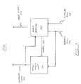
- Computer system 100 includes integrated processor 102, peripheral bus 104, external clock generator 106, bus bridge 108, and peripheral devices 110 through 118.
- Integrated processor 102 receives a clock signal input from external clock generator 106.
- Integrated processor 102 is additionally coupled to peripheral bus 104.
- Peripheral bus 104 is a data communication bus for transferring data between integrated processor 102 and one or more peripheral devices.
- the present invention contemplates any conventional peripheral bus.
- peripheral bus 104 may be a peripheral component interconnect (PCI) bus, an industry standard architecture (ISA) bus or an extended industry standard architecture (EISA) bus.
- PCI peripheral component interconnect
- ISA industry standard architecture
- EISA extended industry standard architecture
- External clock generator 106 generates one or more clock signals provided to integrated processor 102 and bus bridge 108. External clock generator 106 generates clock signals used by portions of computer system 100 for synchronization and timing. External clock generator 106 may provide different clock signals to different portions of computer system 100. For example, external clock generator 106 may provide a CPU clock signal to integrated processor 102 at a different frequency than a peripheral bus clock signal. Portions of computer systems 100 may additionally include circuits for multiplying or dividing the frequency of the clock signal generated by external clock generator 106.
- integrated processor 102 may include an internal clock generator circuit for multiplying the frequency of a clock signal received from external clock generator 106.
- the present invention contemplates any conventional clock generator.
- Peripheral bus 104 is coupled to integrated processor 102, bus bridge 108 and peripherals 110 and 112. As noted above, peripheral bus 104 is a data communication bus coupled between integrated processor 102 and the peripherals of computer system 100. Peripherals 110 and 112 transmit and receive data to and from integrated processor 102 via peripheral bus 104. Peripherals 110 and 112 may be any of a variety of devices, such as disk drives, local area networks interfaces, audio/video devices, etc.
- Peripheral bus 104 is additionally coupled to bus bridge 108.
- Bus bridge 108 provides an interface between peripheral bus 104 and a secondary data communication bus 109.
- peripherals 114 through 118 are coupled to secondary data bus 109.
- Bus bridge 108 allows peripheral bus 104 to be extended to devices not directly compatible with peripheral bus 104.
- peripheral bus 104 may operate at a higher data rate than secondary bus 109. Accordingly, peripheral devices capable of operating at a higher data rate may be coupled directly to peripheral bus 104 while devices not capable of operating at the higher data rate may be coupled to secondary bus 109.
- Data is transferred from the lower data rate peripherals, such as peripheral 114, to the bus bridge, which transfers the data to integrated processor 102 at the higher data rate of peripheral bus 104.
- integrated processor 102 includes processing core 202, memory controller 204, CPU bus 206, bus interface 208, and clock circuit 210.
- Processor core 202, memory controller 204 and bus interface 208 are coupled to CPU bus 206.
- Bus interface 208 interfaces to peripheral bus 104.
- Clock circuit 210 interfaces to bus bridge 208.
- Clock circuit 210 is configured to receive a reference clock signal 216 and an external clock signal 218 from external clock generator 106.
- Clock circuit 210 outputs an internal clock signal 214 and a phase enable signal 212.
- CPU bus 206 interconnects processor core 202, memory controller 204 and bus interface 208. These functional block are included for illustrative purposes only.
- Integrated processor 202 may include additional functional blocks.
- integrated processor 102 may additionally include a DMA controller, a timer, and other conventional functional blocks of an integrated processor.
- peripheral bus 104 is a PCI bus operating at one of two different frequency ranges. In one frequency range, peripheral bus 104 operates at 20 MHz to 33 MHz. In another frequency range, peripheral bus 104 operates at 40 MHz to 66 MHz. In the embodiment in which peripheral bus 104 is a PCI bus operating at the 40 MHz to 66 MHz frequency range, secondary bus 109 may be a PCI bus operating at the 20 MHz to 33 MHz frequency range. In this particular embodiment, peripheral bus 104 may interface to devices capable of operating at the higher frequency range and devices not capable of operating at the higher frequency range. Lower frequency devices are coupled to peripheral bus 104 through bus bridge 108. Higher frequency devices are coupled directly to peripheral bus 104.
- Bus interface 208 is coupled to peripheral bus 104.
- peripheral bus 104 may operate at one of two frequency ranges.
- the first frequency range (20 to 33MHz) will be referred to as 33 MHz
- the second frequency range (40 to 66 MHz) will be referred to as 66MHz.
- bus interface 208 operates at twice the frequency of peripheral bus 104. Accordingly, if peripheral bus 104 is operating at 33 MHz, bus interface 208 operates at 66 MHz. Alternatively, if peripheral bus 104 is operating at 66MHz, then bus interface 208 operates at 132 MHz.
- Clock circuit 210 receives a reference clock signal 216 and an external clock signal 218. Clock circuit 210 generates the timing signals for the functional blocks within integrated processor 102. In the illustrated embodiment, clock circuit 210 generates an internal clock signal 214 and a phase enable signal 212 from reference clock signal 216 and external clock signal 218. In one embodiment, internal clock signal 214 is a clock signal with a frequency twice the frequency of external clock signal 218 and synchronized with external clock signal 218. Phase enable signal 212 is a clock signal that indicates the phase of the external clock signal. In one particular embodiment, phase enable signal 212 is signal that occurs on the rising edge of internal clock signal 214 immediately prior to a rising edge of external clock signal 218. The phase enable signal is discussed in more detail below with reference to Figs. 4, 7 and 8.
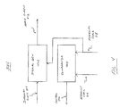
- clock circuit 210 includes a phase-locked loop 302 and a phase detector 304.
- Phase detector 304 is coupled to receive reference clock signal 216 and external clock signal 218.
- Phase detector 304 compares the frequency of reference clock signal 216 to the frequency of external clock signal 218.
- Phase detector 304 outputs a control signal 306 that is indicative of the frequency relationship between reference clock signal 216 and external clock signal 218.
- reference clock signal 216 is a 66 MHz signal
- external clock signal 218 is either a 33 MHz signal or 66 MHz signal.
- phase detector 304 compares reference clock signal 216 to external clock signal 218 to determine whether the clock signals are the same frequency (the same frequency may be the exact same frequency or a frequency within a predefined tolerance). If external clock signal 218 is a 33 MHz signal, control signal 306 will indicate that the signals are a different frequency. Alternatively, if external clock 218 is a 66 MHz signal, control signal 306 will indicate that the signals are the same frequency.
- Phase-locked loop 302 receives reference clock signal 216 and control signal 306. In one embodiment, based upon the state of control signal 306, phase-locked loop 302 outputs an internal clock signal 214 that is either the same frequency as reference clock signal 216 or twice the frequency of reference clock signal 216. Although a phase-locked loop is illustrated in Fig. 3, the present invention contemplates any conventional circuit for generating a clock signal that is a multiple or a fraction of the frequency of an input signal. Phase-locked loop 302 is discussed in more detail below with reference to Fig. 5.
- Internal clock signal 214 provides a timing signal to bus interface 208. Internal clock signal 214 is additionally provided to phase detector 304. Based on internal clock signal 214 and external clock signal 218, phase detector 304 generates phase enable signal 212. Phase enable signal 212 indicates the phase of external clock signal 218 relative to internal clock signal 214. In one embodiment, phase enable signal 212 is a signal asserted at each rising edge of internal clock signal 214 immediately prior to a rising edge of external clock signal 218. Phase enable signal 212 indicates that data will be valid on the subsequent rising edge of external clock signal 218. Phase enable signal 212 is illustrated in Figs. 7 and 8.
- phase detector 304 includes a signal generator 402 and a comparator 404.
- Comparator 404 receives reference clock signal 216 and external clock signal 218. Comparator 404 compares the frequencies of the two input signals and outputs control signal 306.
- Control signal 306 indicates the relative frequencies of the two input signals.
- reference clock signal 216 is a 66 MHz signal and external clock signal 218 is either a 33 MHz or a 66 MHz signal.
- comparator 404 determines if the frequencies of the two clock signals are within a predefined tolerance. If the two clock signals are within a predefined tolerance, control signal 306 is asserted.
- control signal 306 indicates the two input signals have substantially the same frequency. Alternatively, if the frequencies of the two input signals are not within a predefined tolerance (e.g., reference clock signal 216 is 66 MHz and external clock signal 218 is 33 MHz), control signal 306 is deasserted.
- the term "asserted” as used herein may indicate either positive logic in which asserted is a logical high or a logical one, or negative logic in which asserted is a logical low or logical zero.
- Signal generator 402 receives internal clock signal 214 and external clock signal 218, and outputs phase enable signal 212.
- phase enable signal 212 indicates the phase of external clock signal 218 relative to the internal clock signal.
- internal clock signal 214 is twice the frequency of external clock signal 218 and synchronized with external clock signal 218. Accordingly, internal clock signal 214 has two rising edges for each rising edge of external clock signal 218. One rising edge occurs in phase with the rising edge of external clock signal 218 (i.e., the rising edges occur substantially at the same time), and the other rising edge occurs out of phase with external clock signal 218 (i.e., the rising edge of the internal clock signal occurs at substantially the same time as the falling edge of the external clock signal).
- phase detector 304 outputs phase enable signal 212 to indicate which rising edges of internal clock signal 214 are in-phase with the rising edges of external clock signal 218.
- phase enable signal 212 is output by signal generator 402.
- Signal generator 402 outputs a signal on the rising edge of internal clock signal 214 that is out-of-phase with external clock signal 218.
- Bus interface circuit 208 may use phase enable signal 212 as an indication that the next rising edge of internal clock signal 214 will be in-phase with a rising edge of external clock signal 218.
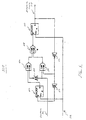
- phase-locked loop 302 includes phase comparator 502, filter 504, voltage-controlled oscillator (VCO) 506, divider 508, and feedback circuit 510.
- VCO 506 outputs a clock signal at twice the highest frequency desired for internal clock signal 214.
- the frequency of output signal 512 of VCO 506 is 264 MHz.
- Output signal 512 of VCO 506 is input to divider 508.
- Divider 508 also receives control signal 306 from phase detector 304. In one embodiment, divider 508 divides the frequency of output signal 512 by either two or four, depending upon the state of control signal 306. Divider 508 divides the frequency of the clock signal by two if control signal 306 is asserted and divides the clock frequency by four if control signal 306 is deasserted.
- output signal 512 of VCO 506 has a frequency of 264 MHZ. Accordingly, the output of divider 508 is 132 MHZ or 66 MHZ in dependence upon the state of control signal 306.
- Feedback circuit 510 divides the frequency of the signal and couples the divided frequency to phase comparator 502.
- feedback circuit 5108 receives control signal 316 and divides the frequency of the signal by two if control signal 306 is asserted and does not divide the frequency of the signal if control signal 306 is deasserted.
- Phase comparator 502 compares the divided feedback signal from feedback circuit 510 to reference clock signal 216. Phase comparator 502 outputs an error signal indicative of the frequency difference between the output of feedback circuit 510 and reference clock signal 216. If the frequencies are the same, phase comparator 502 outputs a null signal. Alternatively, if one frequency is greater than the other, phase comparator 502 outputs an error signal with a voltage proportional to the difference in frequency.
- the error signal from phase comparator 502 is input as a filter 504.
- Filter 504 is typically a low-pass filter which limits the frequency at which the error signal can vary and insures the stability of the circuit.
- the filtered error signal from filter 504 is input to VCO 506, which adjusts the frequency of output 512 based upon the voltage of the error signal. If the frequency of the signal fed-back from VCO 506 is greater than the frequency of reference clock signal 516, the error signal will cause VCO 506 to decrease the frequency of output signal 512. Alternatively, if the frequency of the signal fed-back from VCO 506 is less than the frequency of reference clock signal 516, the error signal will cause VCO 506 to increase the frequency of output signal 512.
- Divider 508 includes flip-flops 602 and 610, NAND gates 606, 608 and 612, inverters 604 and 616, and buffer 614.
- divider circuit 508 divides the frequency of output signal 512 by two or four in dependence upon the state of control signal 306. If control signal 306 is asserted, divider 508 divides the frequency by two. If control signal 306 is deasserted, divider 508 divides the frequency by four.
- control signal 306 is asserted (in this illustrated embodiment asserted is a logical one)
- the output of inverter 604 is deasserted, which asserts the output of NAND gate 606 regardless of the state of flip-flop 602.
- NAND gate 608 and 612 each have one input asserted, the NAND gates invert the remaining input. Accordingly, when control signal 306 is asserted, divider circuit 508 effectively reduces to flip-flop 610 with its output Q coupled to its input D through three inverting circuits (inverter 116, NAND gate 112, and NAND gate 608).
- flip-flop 610 divides the frequency of its clock input by two and outputs the signal as internal clock signal 214.
- NAND gates 606 and 608 act as inverters because each has one asserted input. Accordingly, divider 508 effectively reduces to the output Q of flip-flop 602 coupled to the input D of flip-flop 610 through two inverting circuits (NAND gates 606 and 608) and the Q output of flip-flop 610 is coupled to the D input of flip-flop 602 through inverter 616 and buffer 614.
- the two series connected flip-flops divide the frequency of input clock signal 512 by four and output the signal as internal clock signal 214.
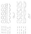
- Fig. 7 a timing diagram illustrating the timing relationship between reference clock signal 216, external clock signal 218, internal clock signal 214 and phase enable signal 212 is shown according to one embodiment of the present invention.
- the frequency of external clock signal 218 is the same frequency as reference clock signal 216.
- control signal 306 is asserted and phase-locked loop 302 outputs internal clock signal 214 at twice the frequency of reference clock signal 216.
- Phase enable 212 is asserted on a rising edge of internal clock signal 214 immediately prior to a rising edge of external clock signals 218.
- phase enable signal 212 is asserted on a rising edge of internal clock signal 214 out-of-phase with the rising edge of external clock 218.
- phase enable signal 212 is asserted on a rising edge of reference clock signal 214 immediately prior to a rising edge of external clock signal 218.
Landscapes
- Engineering & Computer Science (AREA)
- Theoretical Computer Science (AREA)
- Physics & Mathematics (AREA)
- General Engineering & Computer Science (AREA)
- General Physics & Mathematics (AREA)
- Stabilization Of Oscillater, Synchronisation, Frequency Synthesizers (AREA)
Applications Claiming Priority (2)
| Application Number | Priority Date | Filing Date | Title |
|---|---|---|---|
| US08/938,530 US6081143A (en) | 1997-09-26 | 1997-09-26 | Frequency comparison and generation in an integrated processor |
| US938530 | 1997-09-26 |
Publications (1)
| Publication Number | Publication Date |
|---|---|
| EP0905602A2 true EP0905602A2 (fr) | 1999-03-31 |
Family
ID=25471557
Family Applications (1)
| Application Number | Title | Priority Date | Filing Date |
|---|---|---|---|
| EP98307779A Withdrawn EP0905602A2 (fr) | 1997-09-26 | 1998-09-24 | Comparaison et génération de fréquence dans un processeur intégré |
Country Status (2)
| Country | Link |
|---|---|
| US (1) | US6081143A (fr) |
| EP (1) | EP0905602A2 (fr) |
Cited By (2)
| Publication number | Priority date | Publication date | Assignee | Title |
|---|---|---|---|---|
| WO2006124117A2 (fr) | 2005-05-13 | 2006-11-23 | Packet Digital | Regulation de pics de courant transitoire |
| US11442494B2 (en) | 2020-06-08 | 2022-09-13 | Analog Devices, Inc. | Apparatus and methods for controlling a clock signal |
Families Citing this family (14)
| Publication number | Priority date | Publication date | Assignee | Title |
|---|---|---|---|---|
| US6272439B1 (en) * | 1998-02-24 | 2001-08-07 | Vlsi Technology, Inc. | Programmable delay path circuit and operating point frequency detection apparatus |
| US6449728B1 (en) * | 1999-08-31 | 2002-09-10 | Motorola, Inc. | Synchronous quad clock domain system having internal and external sample logic units matching internal and external sample signatures to a pattern corresponding to a synchronous multiple ratio |
| US6484222B1 (en) * | 1999-12-06 | 2002-11-19 | Compaq Information Technologies Group, L.P. | System for incorporating multiple expansion slots in a variable speed peripheral bus |
| KR100335499B1 (ko) * | 1999-12-30 | 2002-05-08 | 윤종용 | 지연시간차를 보상하는 폐루프 아날로그 동기화 지연 시간반영 기법 구조의 클락 발생회로 |
| DE10255355A1 (de) * | 2002-11-27 | 2004-06-24 | Infineon Technologies Ag | Verfahren zur automatischen Erkennung der Taktfrequenz eines Systemtaktes für die Konfiguration einer Peripherie-Einrichtung |
| JP4152795B2 (ja) * | 2003-04-03 | 2008-09-17 | 株式会社ルネサステクノロジ | マイクロコントローラ |
| JP4136822B2 (ja) * | 2003-07-31 | 2008-08-20 | 富士通株式会社 | 半導体集積回路装置、クロック制御方法及びデータ転送制御方法 |
| US7376849B2 (en) * | 2004-06-30 | 2008-05-20 | Intel Corporation | Method, apparatus and system of adjusting one or more performance-related parameters of a processor |
| KR100629389B1 (ko) * | 2004-07-20 | 2006-09-29 | 삼성전자주식회사 | 주파수 측정 회로 및 이를 이용한 반도체 메모리 장치 |
| CN100546306C (zh) * | 2006-09-30 | 2009-09-30 | 华为技术有限公司 | 一种实现业务类型自适应的方法及装置 |
| US20180317019A1 (en) * | 2013-05-23 | 2018-11-01 | Knowles Electronics, Llc | Acoustic activity detecting microphone |
| US20250055667A1 (en) * | 2023-08-13 | 2025-02-13 | Mellanox Technologies, Ltd. | Clock synchronization using digitally controlled oscillator |
| US12289389B2 (en) * | 2023-08-13 | 2025-04-29 | Mellanox Technologies, Ltd. | Physical layer syntonization using digitally controlled oscillator |
| US12615130B2 (en) | 2024-04-02 | 2026-04-28 | Mellanox Technologies, Ltd | Environmental-based parameters optimization of clock |
Family Cites Families (6)
| Publication number | Priority date | Publication date | Assignee | Title |
|---|---|---|---|---|
| US4745371A (en) * | 1985-08-02 | 1988-05-17 | Libera Developments Limited | Phase-locked digital synthesizer |
| CA1282464C (fr) * | 1985-10-23 | 1991-04-02 | Masanori Ienaka | Oscillateur a phase asservie |
| US4812783A (en) * | 1986-08-26 | 1989-03-14 | Matsushita Electric Industrial Co., Ltd. | Phase locked loop circuit with quickly recoverable stability |
| CA1290407C (fr) * | 1986-12-23 | 1991-10-08 | Shigeki Saito | Synthetiseur de frequence |
| US5061882A (en) * | 1987-02-09 | 1991-10-29 | Nikon Corporation | Power supply frequency regulating device for vibration wave driven motor |
| JP3388527B2 (ja) * | 1995-03-06 | 2003-03-24 | 日本電信電話株式会社 | 分数n分周器およびこれを用いた分数n周波数シンセサイザ |
-
1997
- 1997-09-26 US US08/938,530 patent/US6081143A/en not_active Expired - Lifetime
-
1998
- 1998-09-24 EP EP98307779A patent/EP0905602A2/fr not_active Withdrawn
Cited By (3)
| Publication number | Priority date | Publication date | Assignee | Title |
|---|---|---|---|---|
| WO2006124117A2 (fr) | 2005-05-13 | 2006-11-23 | Packet Digital | Regulation de pics de courant transitoire |
| EP1880469A4 (fr) * | 2005-05-13 | 2008-06-11 | Packet Digital | Regulation de pics de courant transitoire |
| US11442494B2 (en) | 2020-06-08 | 2022-09-13 | Analog Devices, Inc. | Apparatus and methods for controlling a clock signal |
Also Published As
| Publication number | Publication date |
|---|---|
| US6081143A (en) | 2000-06-27 |
Similar Documents
| Publication | Publication Date | Title |
|---|---|---|
| US6081143A (en) | Frequency comparison and generation in an integrated processor | |
| US6931086B2 (en) | Method and apparatus for generating a phase dependent control signal | |
| US5771264A (en) | Digital delay lock loop for clock signal frequency multiplication | |
| US6600345B1 (en) | Glitch free clock select switch | |
| US6239627B1 (en) | Clock multiplier using nonoverlapping clock pulses for waveform generation | |
| US6211739B1 (en) | Microprocessor controlled frequency lock loop for use with an external periodic signal | |
| US5564042A (en) | Asynchronous clock switching between first and second clocks by extending phase of current clock and switching after a predetermined time and appropriated transitions | |
| US5777500A (en) | Multiple clock source generation with independently adjustable duty cycles | |
| US6049887A (en) | Method and apparatus for propagating a signal between synchronous clock domains operating at a non-integer frequency ratio | |
| US5691660A (en) | Clock synchronization scheme for fractional multiplication systems | |
| US20080174347A1 (en) | Clock synchronization system and semiconductor integrated circuit | |
| US11275708B2 (en) | System on chip including clock management unit and method of operating the system on chip | |
| US6104251A (en) | Method and apparatus for providing transient suppression in a central processor unit (CPU) phase locked loop clock (PLL) clock signal synthesis circuit | |
| US5721890A (en) | Method and apparatus for synchronously detecting phase relationships between a high-frequency clock and a low-frequency clock | |
| US5485602A (en) | Integrated circuit having a control signal for identifying coinciding active edges of two clock signals | |
| US5961649A (en) | Method and apparatus for propagating a signal between synchronous clock domains operating at a non-integer frequency ratio | |
| US6677786B2 (en) | Multi-service processor clocking system | |
| US20080028250A1 (en) | Method, apparatus and program storage device for providing clocks to multiple frequency domains using a single input clock of variable frequency | |
| US6477657B1 (en) | Circuit for I/O clock generation | |
| EP1618461B1 (fr) | Systeme de correction de desalignement dans un reseau de distribution d'horloge utilisant une boucle a verrouillage de phase (pll) et une boucle a verrouillage de delais (dll) | |
| JP2664880B2 (ja) | クロック信号生成方法および装置 | |
| US6021504A (en) | High-speed internal clock synchronizing method and circuit | |
| US5389897A (en) | Method of and apparatus for limiting the free running frequency in multiplying phase-locked loop circuits | |
| US6928575B2 (en) | Apparatus for controlling and supplying in phase clock signals to components of an integrated circuit with a multiprocessor architecture | |
| US6092129A (en) | Method and apparatus for communicating signals between circuits operating at different frequencies |
Legal Events
| Date | Code | Title | Description |
|---|---|---|---|
| PUAI | Public reference made under article 153(3) epc to a published international application that has entered the european phase |
Free format text: ORIGINAL CODE: 0009012 |
|
| AK | Designated contracting states |
Kind code of ref document: A2 Designated state(s): AT BE CH CY DE DK ES FI FR GB GR IE IT LI LU MC NL PT SE |
|
| AX | Request for extension of the european patent |
Free format text: AL;LT;LV;MK;RO;SI |
|
| RAP1 | Party data changed (applicant data changed or rights of an application transferred) |
Owner name: SUN MICROSYSTEMS, INC. |
|
| STAA | Information on the status of an ep patent application or granted ep patent |
Free format text: STATUS: THE APPLICATION HAS BEEN WITHDRAWN |
|
| 18W | Application withdrawn |
Effective date: 20030915 |