EP0905604A2 - Interface de connection sans fils - Google Patents
Interface de connection sans fils Download PDFInfo
- Publication number
- EP0905604A2 EP0905604A2 EP98307573A EP98307573A EP0905604A2 EP 0905604 A2 EP0905604 A2 EP 0905604A2 EP 98307573 A EP98307573 A EP 98307573A EP 98307573 A EP98307573 A EP 98307573A EP 0905604 A2 EP0905604 A2 EP 0905604A2
- Authority
- EP
- European Patent Office
- Prior art keywords
- motherboard
- computer system
- board
- circuit board
- power
- Prior art date
- Legal status (The legal status is an assumption and is not a legal conclusion. Google has not performed a legal analysis and makes no representation as to the accuracy of the status listed.)
- Withdrawn
Links
Images


Classifications
-
- G—PHYSICS
- G06—COMPUTING OR CALCULATING; COUNTING
- G06F—ELECTRIC DIGITAL DATA PROCESSING
- G06F1/00—Details not covered by groups G06F3/00 - G06F13/00 and G06F21/00
- G06F1/16—Constructional details or arrangements
- G06F1/18—Packaging or power distribution
- G06F1/183—Internal mounting support structures, e.g. for supporting printed circuit boards
Definitions
- the invention relates to a cableless interface connection for a computer system.
- the central processing circuitry of a personal computer system typically is located on a specialized system board called a motherboard. This circuitry typically has to communicate with other circuitry located on system boards separate from the motherboard. As a result, these other system boards are electrically connected to the motherboard.
- a board called a riser board has expansion slot connectors for receiving removable circuit cards (e.g., ISA/EISA and PCI cards).
- the riser board typically plugs into the motherboard to electrically connect the removable circuit cards to circuitry on the motherboard.
- a board called a peripheral backplane board has connectors that receive corresponding connectors of mass storage devices (e.g., IDE, SCSI and floppy disk drive devices) and, to establish communication between the mass storage devices and circuitry on the motherboard, cables extend from the peripheral backplane board to the motherboard.
- mass storage devices e.g., IDE, SCSI and floppy disk drive devices
- power supply cables typically extend from a power supply backplane board to the motherboard. Because circuitry on the other system boards need power as well, typically other power supply cables extend from the power supply board to these boards. Power supply cables also typically extend to peripheral devices, such as a floppy disk drive, a hard disk drive and a CD-ROM drive.
- the system boards are typically mounted to and encased by a chassis which places limits on where the cables may be routed.
- cables typically compete for space with large central processing unit (CPU), heatsinks and tall memory modules that extend upwardly from the motherboard.
- CPU central processing unit
- heatsinks and tall memory modules that extend upwardly from the motherboard.
- system designers typically take into account the space required by the cables when designing the chassis.
- the invention features a computer system that has a motherboard, a power supply and a first circuit board.
- the motherboard has power consuming circuitry.
- a first circuit board is configured to form a rigid connection with the motherboard and route power from the power supply to the motherboard through the rigid connection.
- the advantages of the invention may include one or more of the following. Cable clutter is reduced. Air flow around heat sinks is improved. More space is provided for tall components (e.g., heat sinks and memory modules) of the motherboard.
- the computer system costs less and is more reliable. The computer system is easier to service. The computer system is easier to manufacture. The motherboard may be quickly accessed and serviced. The size of a chassis is minimized. Full length PCI and full length EISA/ISA cards may be accommodated by the computer.
- the rigid connection may include a first rigid connector (e.g., an edge of the motherboard) of the motherboard and a second rigid connector of the first circuit board.
- the first rigid connector may be configured to mate with the second rigid connector.
- the first circuit board may have at least one conductive trace configured to carry the power. This conductive trace may have a predetermined voltage level.
- the computer system may also have a second circuit board (e.g., a peripheral backplane board) that has power consuming circuitry, and the motherboard may be configured to route a portion of the power to the second circuit board.
- the motherboard and the second circuit board may be configured to form a second rigid connection and route the portion of the power through the second rigid connection.
- the second circuit board may have a third rigid connector, and the motherboard may have a fourth rigid connector that is configured to mate with the third rigid connector to form the second rigid connection.
- the invention features a computer system that includes a power supply, a motherboard and a link.
- the link is configured to transfer power from the power supply to the motherboard.
- the link does not include a flexible connector.
- the invention features a computer system that includes a peripheral backplane board that is configured to carry peripheral communication signals.
- the computer system has a motherboard that is configured to form a rigid connection with the peripheral backplane board and route the peripheral communication signals through the rigid connection.
- the invention features a computer system that has a motherboard, an expansion card backplane board, a peripheral backplane board and a power supply backplane board.
- the motherboard, expansion card backplane board, the peripheral backplane board and the power supply backplane board are electrically connected together without using a flexible connector.
- the invention features a method for use with a computer system.
- the computer system has a motherboard having power consuming circuitry and a power supply.
- the method includes forming a rigid connection between a first circuit board and the motherboard and routing power from the power supply to the motherboard through the rigid connection.
- the invention features a method for use with a computer system having a motherboard and a power supply.
- the method includes transferring power from the power supply to the motherboard without using a flexible connector.
- the invention features a method for use with a computer system having a peripheral backplane board that is configured to carry peripheral communication signals and a motherboard.
- the method includes forming a rigid connection between the peripheral backplane board and the motherboard and routing the peripheral communication signals through the rigid connection.
- the invention features a method for use with a computer system
- the method includes electrically connecting a motherboard, an expansion card backplane board, a peripheral backplane board and a power supply backplane board together without using a flexible connector.
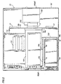
- Fig. 1 is a perspective view of a computer system.
- Fig. 2 is a cross-sectional view taken along line 2-2 of Fig. 1.
- Figs. 3 and 4 are views of flexible connectors
- Fig. 5 is a top view of rigid connectors.
- Fig. 5A is a cross-sectional view taken along line 5A-5A of Fig. 5.
- Fig. 6 is an exploded perspective view of the computer system.
- Figs. 7, 8 and 9 are views of system boards of the computer system.
- Fig. 10 is an electrical schematic diagram of the computer system.
- system boards 12 of a computer system 10 are constructed and arranged in a manner to form a cableless network for carrying power and communication signals among the boards 12.
- the boards 12 are arranged so that adjacent, orthogonal boards 12 plug into each other and are constructed so that traditional cabling between the boards 12 is replaced by circuitry of the boards 12.
- a power supply harness cable 3 00 (see Fig. 3)
- a power supply harness cable 3 00 has traditionally been used to electrically connect system boards to a power supply backplane board so that the boards 12 have power to operate.
- one end plug 302 of the cable 300 is plugged into the power supply backplane board and the other end plug 302 of the cable 300 is plugged into the system board.
- the cable 300 has also typically been used to extend power to a peripheral device, such as a floppy disk drive, a hard drive or a CD-ROM drive.
- Flexible wires 301 extend between the end plugs 302 and provide flexibility in running and connecting the cable 300.
- the wires 301 include, for example, DC voltage supply wires and ground wires.
- a ribbon cable 305 has typically been used to electrically connect bus communication signals (e.g., signals from a Small Communication Systems Interface (SCSI) bus or an Intelligent Electronics Device (IDE) bus) of a motherboard to a backplane board (e.g., a riser board or a peripheral device backplane board)
- bus communication signals e.g., signals from a Small Communication Systems Interface (SCSI) bus or an Intelligent Electronics Device (IDE) bus
- IDE Intelligent Electronics Device
- the ribbon cable 305 has one end plug 308 that connects to the motherboard, and another end plug 308 that connects to the backplane board.
- a plastic web of flexible wires 305 extends between the two end plugs 308.
- the ribbon cable 305 provides flexibility in running and connecting the cable 305.
- the system boards 12 of the computer system 10 are constructed and arranged to form a cableless network for distributing power and communication signals throughout the system 10.
- This cableless network is formed from electrical traces on the system boards 12 and rigid, plug-type connectors 16 (see Fig. 2) of the boards 12. These rigid connectors 16 mechanically and electrically connect the boards 12 together.
- the removal of a system board involves disconnecting cables from the board before the board is removed.
- the installation of a system board includes connecting cables to the board.
- the boards 12 can be removed from and installed in the system 10 without disconnecting and connecting cables.
- the connection of cables to boards and peripheral devices typically consumes a considerable amount of time. If the end plug of the cable is not keyed, time must be spent ensuring that the end plug is in the proper orientation before connecting the end plug. Otherwise, a peripheral device or system board failure may occur.
- the cableless network less time is spent servicing boards/peripheral devices of the system 10.
- the boards 12 and peripheral devices can be placed on removable trays.
- the tray on which the board or device is mounted is pulled from the chassis 52.
- the board or device on the tray is automatically unplugged from its electrical connections with boards 12 of the rest of the system 10.
- the boards 12 are also constructed to carry out typical functions of the computer system 10.
- the system boards 12 include a motherboard 12a which is mounted to the bottom of the chassis 52.
- the motherboard 12a is mounted to a removable tray that slides into a rear of the chassis 52.
- the motherboard 12a includes circuitry (e.g., memory modules 13 that extend upwardly from the motherboard 12a and a central processing unit (CPU) 200 (see Fig 10)) that needs to communicate with other system boards 12, such as a peripheral backplane board 12b and an expansion card riser board 12c.
- the motherboard 12a is constructed to form a plug-type connection with the upwardly extending peripheral backplane board 12b and with the upwardly extending riser board 12c.
- the peripheral backplane board 12b is orthogonal to the motherboard 12a, and the front face of the peripheral backplane board 12b faces mass storage devices (e.g., a floppy disk drive 100 and a CD-ROM drive 102).
- the rear face of the backplane board 12b faces the motherboard 12a.
- the mass storage devices plug into the front face of the peripheral backplane board 12b, and circuitry on the motherboard 12a communicates with these mass storage devices through the motherboard's plug-type connection with the peripheral backplane board 12b, i.e., through the set of mating connectors 16 that connect the motherboard 12a and the backplane board 12b together.
- SCSI, IDE and floppy drive signals pass through the set of mating connectors 16 that connect the two boards 12a and 12b together.
- the riser board 12c extends from near the rear of the chassis 52 toward the front of the chassis 52, and the faces of the riser board 12c face opposite sides of the chassis 52. Through the riser board's plug-type connection with the motherboard 12a, expansion cards 101 plugged into expansion slots of the riser board 12 can communicate with circuitry of the motherboard 12a and the mass storage devices.
- the system boards 12 are connected to each other not only for purposes of communication but also to form a power distribution network. In this manner, the boards 12 cooperate to distribute, or transfer, power from a power supply 50 throughout the system 10 without using cables.
- the power supply 50 located near the rear of the chassis 52, is constructed to form a plug-type connection with an upwardly extending power supply backplane board 12d that faces the front and rear of the chassis 52.
- cables extend from the power supply backplane board 12d to distribute power to the system boards 12.
- the riser board 12c is also constructed to form a rigid, plug-type connection with the power supply backplane board 12d, and all power leaving the power supply backplane board 12d goes through this rigid connection and onto the riser board 12c.
- the power distribution network uses power buses 25 that are formed on the boards 12.
- Each power bus 25 includes conductive traces that carry different DC supply voltage levels (e.g., 3.3 V, 5 V, -5V and 12V levels).
- the power supply backplane board 12d has a bus 12c that is constructed to carry power from the power supply 50 to the riser board 12c.
- the riser board 12c has a power bus 25c to transfer supply power to the motherboard 12a
- the motherboard 12a has a power bus 25a (see Fig. 6) to transfer power to the peripheral backplane board 12b (see Fig. 7). All of the power passes through the rigid connections formed between the boards 12, i.e., all of the power passes between adjacent boards 12 through sets of mating connectors 16 that connect the adjacent boards 12 together.
- the plug-type connections between the system boards 12 are formed by a set of two, mating rigid connectors 16 (e.g., a card edge connector and a mating card edge). Because the rigid connectors 16 are part of the system boards 12, the rigid connectors 16 consume a minimal amount of space.
- Each set of connectors 16 includes a male connector 16a (part of one system board) that is configured to mate with a female connector 16b (part ofthe other, mating system board).
- the male connector 16a is formed from a plug extension 18 of the board 12 and conductive traces, or fingers 19, that are located on the top and bottom faces of the plug extension 18.
- the female connector 16b has internal spring contacts 20 (see Fig. 5A) that are configured to contact the fingers 19 when the connectors 16a and 16b are plugged together.
- Other rigid connectors 16 may be used.
- the construction and arrangement of the system boards 12 establish both a power supply network and a communication network for the computer system 10. All of the signals in these networks pass through the connectors 16.
- the plug-type connections between the boards 12 also allows quick assembly and disassembly of the system 10.
- the motherboard 12a and riser board 12c may be easily removed from the chassis 52 by pulling on the motherboard 12a to dislodge the motherboard 12a from the peripheral backplane board 12b and disconnect the riser board 12c from the power supply backplane board 12d.
- the motherboard 12a and the power supply 50 are mounted on a tray that slides into the rear of the chassis, and the peripheral backplane board 12b is permanently mounted to the chassis.
- the motherboard 12a and power supply 50 are removed from the chassis by simply pulling the tray from the chassis, and the motherboard 12a and power supply 50 are installed by pushing the tray into the chassis.
- the motherboard 12a has at least one central processing unit (CPU) 200, a system memory controller/host bridge circuit 204 and a system memory 206, all of which are connected to a local bus 202.
- the circuit 204 interfaces the local bus 202 to a primary Peripheral Component Interconnect (PCI) bus 208.
- PCI Peripheral Component Interconnect
- Also on the motherboard 12a is a PCI-PCI bridge circuit 212 that interfaces the bus 208 to circuitry of one or more expansion cards through a secondary PCI bus 214.
- the bus 214 is located on the motherboard 12a and is extended to PCI expansion cards through one or more expansion slot connectors 19 (see Fig. 8) on the riser board 12c.
- an IDE controller 224 and a video controller 226 which are coupled to the PCI bus 214.
- the controller 224 is located on an expansion card, and in some arrangements, the video controller 226 is located on an expansion card.
- the controller 224 controls operation of the IDE devices, such as the CD-ROM drive 100.
- the video controller 226 drives a monitor 228.
- ISA PCI-Industry Standard Architecture
- the circuit 210 interfaces the PCI bus 208 to an ISA bus 216 which is extended to ISA expansion cards through one or more ISA slot connectors 27 (see Fig. 8) on the riser board 12c.
- I/O input/output
- ROM read only memory
- the I/O circuit 218 receives input from input/output devices, such as a keyboard 220 and a mouse 222.
- the I/O circuit 218 also controls operations of the floppy disk drive 102. In some arrangements, all or part of the circuitry connected to the ISA bus 216 are located on expansion cards.
Landscapes
- Engineering & Computer Science (AREA)
- Theoretical Computer Science (AREA)
- Computer Hardware Design (AREA)
- Power Engineering (AREA)
- Human Computer Interaction (AREA)
- Physics & Mathematics (AREA)
- General Engineering & Computer Science (AREA)
- General Physics & Mathematics (AREA)
- Power Sources (AREA)
- Mounting Of Printed Circuit Boards And The Like (AREA)
- Coupling Device And Connection With Printed Circuit (AREA)
Applications Claiming Priority (2)
| Application Number | Priority Date | Filing Date | Title |
|---|---|---|---|
| US94058297A | 1997-09-30 | 1997-09-30 | |
| US940582 | 1997-09-30 |
Publications (2)
| Publication Number | Publication Date |
|---|---|
| EP0905604A2 true EP0905604A2 (fr) | 1999-03-31 |
| EP0905604A3 EP0905604A3 (fr) | 2000-06-21 |
Family
ID=25475089
Family Applications (1)
| Application Number | Title | Priority Date | Filing Date |
|---|---|---|---|
| EP98307573A Withdrawn EP0905604A3 (fr) | 1997-09-30 | 1998-09-17 | Interface de connection sans fils |
Country Status (2)
| Country | Link |
|---|---|
| EP (1) | EP0905604A3 (fr) |
| JP (1) | JPH11175196A (fr) |
Cited By (1)
| Publication number | Priority date | Publication date | Assignee | Title |
|---|---|---|---|---|
| EP1094425B1 (fr) * | 1999-10-06 | 2016-03-30 | Igt | Communication periphérique standard |
Families Citing this family (2)
| Publication number | Priority date | Publication date | Assignee | Title |
|---|---|---|---|---|
| US8131903B2 (en) * | 2007-04-30 | 2012-03-06 | Hewlett-Packard Development Company, L.P. | Multi-channel memory connection system and method |
| KR100921526B1 (ko) | 2009-02-10 | 2009-10-12 | (주)넷메이커 | 1u형 서버 컴퓨터용 밀착형 멀티보드 및 이를 구비한 1u형 서버 컴퓨터 |
Family Cites Families (5)
| Publication number | Priority date | Publication date | Assignee | Title |
|---|---|---|---|---|
| GB2271446B (en) * | 1992-04-29 | 1996-01-31 | Hany Neoman | User assembled and upgradable computer systems |
| EP0977127A2 (fr) * | 1994-03-11 | 2000-02-02 | The Panda Project | Méthode de configuration d'un système d'ordinateur |
| NL9400967A (nl) * | 1994-06-14 | 1996-01-02 | Tulip Computers International | Moederbord voor een computer van het AT-type, alsmede een computer van het AT-type, voorzien van een dergelijk moederbord. |
| US5557506A (en) * | 1995-03-31 | 1996-09-17 | Alantec | Expandable data processing chassis and method of assembly thereof |
| GB9526156D0 (en) * | 1995-12-21 | 1996-02-21 | Neoman Hany | Computer bus systems |
-
1998
- 1998-09-17 EP EP98307573A patent/EP0905604A3/fr not_active Withdrawn
- 1998-09-28 JP JP10272685A patent/JPH11175196A/ja active Pending
Cited By (1)
| Publication number | Priority date | Publication date | Assignee | Title |
|---|---|---|---|---|
| EP1094425B1 (fr) * | 1999-10-06 | 2016-03-30 | Igt | Communication periphérique standard |
Also Published As
| Publication number | Publication date |
|---|---|
| EP0905604A3 (fr) | 2000-06-21 |
| JPH11175196A (ja) | 1999-07-02 |
Similar Documents
| Publication | Publication Date | Title |
|---|---|---|
| US5986880A (en) | Electronic apparatus having I/O board with cable-free redundant adapter cards thereon | |
| EP1053580B1 (fr) | Connexion amelioree pour systeme d'alimentation de module de puissance | |
| US4401351A (en) | Expandable card cage | |
| US6137678A (en) | Configuring a computer system | |
| US6363450B1 (en) | Memory riser card for a computer system | |
| KR101435153B1 (ko) | 분할된 멀티 커넥터 소자 차동 버스 커넥터를 사용하는 전자 디바이스들 | |
| US6247078B1 (en) | Computer interface for integrating a first computer into a second computer | |
| US6146150A (en) | Circuit card with separate interfaces for different bus architectures | |
| US20140185255A1 (en) | Method to Use Empty Slots in Onboard Aircraft Servers and Communication Devices to Install Non-Proprietary Servers and Communications Interfaces | |
| US20060009048A1 (en) | Expansible interface for modularized printed circuit boards | |
| US6504725B1 (en) | Topology for PCI bus riser card system | |
| US6496364B1 (en) | Upgradeable system and method for connecting a 1U personal computer | |
| US10624211B2 (en) | Motherboard with daughter input/output board | |
| US20020081890A1 (en) | Printed circuit card carrier for longitudinal on-line replacement | |
| US6634889B2 (en) | Cross-connected card-edge socket connector and card-edge | |
| EP0692927A2 (fr) | Plaque à circuit imprimé améliorée et méthode | |
| JPH1185321A (ja) | コネクタ装置、情報処理装置およびネットワーク装置 | |
| EP0905604A2 (fr) | Interface de connection sans fils | |
| US5987553A (en) | Adaptor board interconnection for a processor board and motherboard | |
| US20090190297A1 (en) | Motherboard expansion device | |
| CN120834477A (zh) | 用于竖直安装扩展卡的转接卡 | |
| EP1228675A1 (fr) | Support de carte a circuit imprime pour alignement longitudinal | |
| US20050068754A1 (en) | System and method for a self aligning multiple card enclosure with hot plug capability | |
| CN116560465A (zh) | 供电系统以及更换方法 | |
| US12444893B2 (en) | Optimized cable solution |
Legal Events
| Date | Code | Title | Description |
|---|---|---|---|
| PUAI | Public reference made under article 153(3) epc to a published international application that has entered the european phase |
Free format text: ORIGINAL CODE: 0009012 |
|
| AK | Designated contracting states |
Kind code of ref document: A2 Designated state(s): DE FR GB |
|
| AX | Request for extension of the european patent |
Free format text: AL;LT;LV;MK;RO;SI |
|
| PUAL | Search report despatched |
Free format text: ORIGINAL CODE: 0009013 |
|
| AK | Designated contracting states |
Kind code of ref document: A3 Designated state(s): AT BE CH CY DE DK ES FI FR GB GR IE IT LI LU MC NL PT SE |
|
| AX | Request for extension of the european patent |
Free format text: AL;LT;LV;MK;RO;SI |
|
| 17P | Request for examination filed |
Effective date: 20001204 |
|
| AKX | Designation fees paid |
Free format text: DE FR GB |
|
| 17Q | First examination report despatched |
Effective date: 20020429 |
|
| STAA | Information on the status of an ep patent application or granted ep patent |
Free format text: STATUS: THE APPLICATION IS DEEMED TO BE WITHDRAWN |
|
| 18D | Application deemed to be withdrawn |
Effective date: 20020910 |