EP0905672A1 - Mehrschichtige Anzeigetafelkonstruktion und Steuerverfahren dafür - Google Patents
Mehrschichtige Anzeigetafelkonstruktion und Steuerverfahren dafür Download PDFInfo
- Publication number
- EP0905672A1 EP0905672A1 EP98307759A EP98307759A EP0905672A1 EP 0905672 A1 EP0905672 A1 EP 0905672A1 EP 98307759 A EP98307759 A EP 98307759A EP 98307759 A EP98307759 A EP 98307759A EP 0905672 A1 EP0905672 A1 EP 0905672A1
- Authority
- EP
- European Patent Office
- Prior art keywords
- electrode layer
- display element
- display
- strobe signal
- strobe
- Prior art date
- Legal status (The legal status is an assumption and is not a legal conclusion. Google has not performed a legal analysis and makes no representation as to the accuracy of the status listed.)
- Withdrawn
Links
- 238000000034 method Methods 0.000 title claims description 29
- 238000004544 sputter deposition Methods 0.000 description 7
- 239000003086 colorant Substances 0.000 description 6
- 239000000463 material Substances 0.000 description 6
- QVGXLLKOCUKJST-UHFFFAOYSA-N atomic oxygen Chemical compound [O] QVGXLLKOCUKJST-UHFFFAOYSA-N 0.000 description 5
- 239000001301 oxygen Substances 0.000 description 5
- 229910052760 oxygen Inorganic materials 0.000 description 5
- 239000000758 substrate Substances 0.000 description 5
- 230000000694 effects Effects 0.000 description 4
- 238000004519 manufacturing process Methods 0.000 description 4
- 230000005684 electric field Effects 0.000 description 3
- 239000011521 glass Substances 0.000 description 3
- 239000011159 matrix material Substances 0.000 description 3
- 230000006798 recombination Effects 0.000 description 3
- 238000005215 recombination Methods 0.000 description 3
- TVIVIEFSHFOWTE-UHFFFAOYSA-K tri(quinolin-8-yloxy)alumane Chemical compound [Al+3].C1=CN=C2C([O-])=CC=CC2=C1.C1=CN=C2C([O-])=CC=CC2=C1.C1=CN=C2C([O-])=CC=CC2=C1 TVIVIEFSHFOWTE-UHFFFAOYSA-K 0.000 description 3
- 239000005725 8-Hydroxyquinoline Substances 0.000 description 2
- XKRFYHLGVUSROY-UHFFFAOYSA-N Argon Chemical compound [Ar] XKRFYHLGVUSROY-UHFFFAOYSA-N 0.000 description 2
- 239000000956 alloy Substances 0.000 description 2
- 229910045601 alloy Inorganic materials 0.000 description 2
- 229910052782 aluminium Inorganic materials 0.000 description 2
- XAGFODPZIPBFFR-UHFFFAOYSA-N aluminium Chemical compound [Al] XAGFODPZIPBFFR-UHFFFAOYSA-N 0.000 description 2
- 239000004411 aluminium Substances 0.000 description 2
- 230000015572 biosynthetic process Effects 0.000 description 2
- 238000010586 diagram Methods 0.000 description 2
- 239000007789 gas Substances 0.000 description 2
- AMGQUBHHOARCQH-UHFFFAOYSA-N indium;oxotin Chemical compound [In].[Sn]=O AMGQUBHHOARCQH-UHFFFAOYSA-N 0.000 description 2
- 238000002347 injection Methods 0.000 description 2
- 239000007924 injection Substances 0.000 description 2
- 229960003540 oxyquinoline Drugs 0.000 description 2
- XOLBLPGZBRYERU-UHFFFAOYSA-N tin dioxide Chemical compound O=[Sn]=O XOLBLPGZBRYERU-UHFFFAOYSA-N 0.000 description 2
- 229910001316 Ag alloy Inorganic materials 0.000 description 1
- MYMOFIZGZYHOMD-UHFFFAOYSA-N Dioxygen Chemical compound O=O MYMOFIZGZYHOMD-UHFFFAOYSA-N 0.000 description 1
- 229910019015 Mg-Ag Inorganic materials 0.000 description 1
- 229910052786 argon Inorganic materials 0.000 description 1
- HFACYLZERDEVSX-UHFFFAOYSA-N benzidine Chemical compound C1=CC(N)=CC=C1C1=CC=C(N)C=C1 HFACYLZERDEVSX-UHFFFAOYSA-N 0.000 description 1
- 230000015556 catabolic process Effects 0.000 description 1
- 239000002800 charge carrier Substances 0.000 description 1
- 238000010549 co-Evaporation Methods 0.000 description 1
- 230000000295 complement effect Effects 0.000 description 1
- 239000004020 conductor Substances 0.000 description 1
- 230000003247 decreasing effect Effects 0.000 description 1
- 238000006731 degradation reaction Methods 0.000 description 1
- 150000004985 diamines Chemical class 0.000 description 1
- PJXISJQVUVHSOJ-UHFFFAOYSA-N indium(III) oxide Inorganic materials [O-2].[O-2].[O-2].[In+3].[In+3] PJXISJQVUVHSOJ-UHFFFAOYSA-N 0.000 description 1
- 229910010272 inorganic material Inorganic materials 0.000 description 1
- 239000011147 inorganic material Substances 0.000 description 1
- 125000000040 m-tolyl group Chemical group [H]C1=C([H])C(*)=C([H])C(=C1[H])C([H])([H])[H] 0.000 description 1
- 238000001755 magnetron sputter deposition Methods 0.000 description 1
- 230000000873 masking effect Effects 0.000 description 1
- 239000000203 mixture Substances 0.000 description 1
- 239000000615 nonconductor Substances 0.000 description 1
- 230000003287 optical effect Effects 0.000 description 1
- 239000011368 organic material Substances 0.000 description 1
- MCJGNVYPOGVAJF-UHFFFAOYSA-N quinolin-8-ol Chemical compound C1=CN=C2C(O)=CC=CC2=C1 MCJGNVYPOGVAJF-UHFFFAOYSA-N 0.000 description 1
- 230000005855 radiation Effects 0.000 description 1
- 239000000243 solution Substances 0.000 description 1
- 238000002207 thermal evaporation Methods 0.000 description 1
- AYEKOFBPNLCAJY-UHFFFAOYSA-O thiamine pyrophosphate Chemical compound CC1=C(CCOP(O)(=O)OP(O)(O)=O)SC=[N+]1CC1=CN=C(C)N=C1N AYEKOFBPNLCAJY-UHFFFAOYSA-O 0.000 description 1
Images


Classifications
-
- G—PHYSICS
- G09—EDUCATION; CRYPTOGRAPHY; DISPLAY; ADVERTISING; SEALS
- G09G—ARRANGEMENTS OR CIRCUITS FOR CONTROL OF INDICATING DEVICES USING STATIC MEANS TO PRESENT VARIABLE INFORMATION
- G09G3/00—Control arrangements or circuits, of interest only in connection with visual indicators other than cathode-ray tubes
- G09G3/20—Control arrangements or circuits, of interest only in connection with visual indicators other than cathode-ray tubes for presentation of an assembly of a number of characters, e.g. a page, by composing the assembly by combination of individual elements arranged in a matrix no fixed position being assigned to or needed to be assigned to the individual characters or partial characters
- G09G3/22—Control arrangements or circuits, of interest only in connection with visual indicators other than cathode-ray tubes for presentation of an assembly of a number of characters, e.g. a page, by composing the assembly by combination of individual elements arranged in a matrix no fixed position being assigned to or needed to be assigned to the individual characters or partial characters using controlled light sources
- G09G3/30—Control arrangements or circuits, of interest only in connection with visual indicators other than cathode-ray tubes for presentation of an assembly of a number of characters, e.g. a page, by composing the assembly by combination of individual elements arranged in a matrix no fixed position being assigned to or needed to be assigned to the individual characters or partial characters using controlled light sources using electroluminescent panels
-
- H—ELECTRICITY
- H10—SEMICONDUCTOR DEVICES; ELECTRIC SOLID-STATE DEVICES NOT OTHERWISE PROVIDED FOR
- H10K—ORGANIC ELECTRIC SOLID-STATE DEVICES
- H10K59/00—Integrated devices, or assemblies of multiple devices, comprising at least one organic light-emitting element covered by group H10K50/00
- H10K59/30—Devices specially adapted for multicolour light emission
- H10K59/32—Stacked devices having two or more layers, each emitting at different wavelengths
-
- G—PHYSICS
- G09—EDUCATION; CRYPTOGRAPHY; DISPLAY; ADVERTISING; SEALS
- G09G—ARRANGEMENTS OR CIRCUITS FOR CONTROL OF INDICATING DEVICES USING STATIC MEANS TO PRESENT VARIABLE INFORMATION
- G09G2300/00—Aspects of the constitution of display devices
- G09G2300/02—Composition of display devices
- G09G2300/023—Display panel composed of stacked panels
Definitions
- This application relates to a method of driving a display device which has a display element disposed between two electrode layers.
- the method is a passive addressing method, in which a first voltage, known as a "data voltage”, is applied to one of the electrodes and a second voltage, known as a "strobe voltage", a “select voltage” or a “scanning voltage” (hereinafter referred to as a "strobe voltage” for convenience), is applied to the other electrode.
- the invention also relates to a display device.
- the invention particularly relates to electro-luminescent display devices.
- An electro-luminescent device (“EL device”) generates light as a result of electron-hole recombination.
- An EL device typically has a multilayer structure, in which an emitter layer is confined between an electron transporting layer (ETL) and a hole transporting layer (HTL). Charge carrier recombination occurs in the emitter layer and photons are generated. It is possible for one layer to act as both the ETL and the emitter layer, in which case recombination of electrons and holes occurs near the interface between the HTL and the ETL/emitter layer.
- ETL electron transporting layer
- HTL hole transporting layer
- FIGs 1(a) and 1(b) schematically show the structure of two conventional EL devices, which are described in "Journal of Applied Physics", 65 (9), May 1989, pp 3610 - 3616. Both devices have an TO (indium tin oxide) electrode layer 1 disposed on a substrate (not shown). A diamine layer 2 constitutes the HTL in both devices.
- the emitter layer is formed by a layer 3 of 8-hydroxyquinoline aluminium, Alq, which can be either doped or undoped. Electrons are injected from an Mg:Ag electrode 4.
- the emitter layer is formed by a doped layer of Alq 5 located within the Alq layer 3.
- the doped Alq layer adjacent to the HTL layer 2.
- electrons are injected from a Mg:Ag electrode 4.
- each pixel is laterally divided into three sub-pixels, one for each primary colour.
- the three colours can be obtained by using three different emitter materials in the three sub-pixels, or by using an EL device which emits white light and providing each sub-pixel with an appropriate colour filter.
- an EL device with an emitter material which generates blue light is used, red and green sub-pixels can be obtained by using fluorescent colour filters.
- Fig. 2 shows the structure of such an electro-luminescent element.
- the device is grown on a glass substrate 6 coated with an indium tin oxide (ITO) film 7 which acts as a transparent, hole injecting contact.
- ITO indium tin oxide
- the HTL 8 is a 200 ⁇ (20nm) thick layer of the hole conducting material N.N'-diphenyl-N.N'-bis(3-methylphenyl) 1-1'biphenyl-4,4'diamine (TPD), which is deposited by thermal evaporation in a vacuum.
- the ETL/emitter layer 9 is a 400 ⁇ (40nm) thick layer of the electron conducting and light emitting material tris-(8-hydroxyquinoline) aluminium (Alq 3 ).
- EL devices typically have thick, opaque upper electrodes composed of a low work-function alloy such as Mg:Ag for injection of electrons.
- a transparent EL device this is replaced with a layer 10 of Mg:Ag that is thinner than the optical skin depth, followed by an overlayer of ITO 11. This results in a highly transparent top electrode with injection characteristics similar to that of a conventional upper electrode.
- a thin Mg-Ag layer (with a thickness of 50-400 ⁇ (5-40nm)) is deposited through a shadow mask by co-evaporation of Mg and Ag in a ratio of 30:1.
- the sample is then immediately transferred through a load lock to a sputtering chamber.
- the ITO film is then deposited by low-power sputtering.
- the target housed in a magnetron sputtering gun, is 10% SnO 2 and 90% In 2 O 3 by weight with 99% purity.
- the sputtering gas is a mixture of 99.9999% pure argon and 99.998% pure oxygen.
- FIG. 3 shows a further prior art EL display device, which consists of a red EL element 13 stacked on a blue EL element 12. This is described in "Applied Physics Letters" 69 (20) November 1996, pp2606-2608.
- the device has a 1mm glass substrate 14, on which a 2000 ⁇ (200nm) TO electrode 15 is formed.
- Layers 16, 17 and 18 are a 600 ⁇ (60nm) TPD layer, an 800 ⁇ (80nm) Alq' 2 OPh layer and a 360 ⁇ (36nm) Alq 3 layer, and these layers constitute the blue EL element 12.
- Layers 19 and 20 are electrode layers: a 130 ⁇ (13nm) Mg:Al layer and a 550 ⁇ (55nm) TO layer.
- 21 denotes a 600 ⁇ (60nm) TPD layer, and 22 is a 590 ⁇ (59nm) TPP/Alq 3 layer.
- a 1500 ⁇ (150nm) Mg:Al electrode layer 23 and a 500 ⁇ (50nm) Ag layer 24 are provided.
- Layers 20-24 constitute the red EL element.
- each EL element would need its own strobe electrode layer and data electrode layer. If the elements were simply stacked one above another, the strobe electrode layer of one element would be adjacent to the data electrode of another EL element. It would thus be necessary to provide additional insulating layers in the device if the three elements were to be driven simultaneously, and this would complicate the structure of the device. It would be possible to drive the three elements sequentially without providing intermediate insulating layers, but this would reduce the brightness of the display. While the brightness can be restored to the required level by using larger driving voltages, it is undesirable to do this because using larger driving voltages will shorten the lifetime of the device.
- GB-A-2 194 376 discloses a display device having an electrode layer, a first light-emitting layer, a second electrode layer, a second light-emitting layer, and a third electrode layer disposed in this order.
- the first light emitting layer is driven by applying a voltage between the first and second electrode layers
- the second light-emitting layer is driven by applying a voltage between the second electrode layer and the third electrode layer.
- the first and second light-emitting layers are driven sequentially, so that this device suffers from the disadvantages outlined above.
- US-A-4 416 494 discloses an EL device having a first electrode, a first EL layer, a second electrode layer, a second EL layer, and a third electrode layer.
- the second electrode layer is earthed, and an A.C. voltage is applied between the first and third electrode layers. This driving method is adopted so that the voltages applied across the two EL layers are 180° out of phase with one another to suppress the generation of piezoelectric noise.
- US-A-4 777 402 discloses a device having two stacked EL layers.
- An electrode layer is disposed between the two EL layers, and this consists of two separate electrodes.
- a conductive film is placed below the lower EL layer, and another conductive film is placed above the upper EL layer.
- a voltage is applied between the two electrodes making up the electrode layer.
- the conductive films act as equi-potential surfaces, so that an electric field is established between the electrode layer and each of the transparent conductive films. It is not possible to control the electric field applied to one EL element independently from the electric field applied to the other EL element.
- the structure of the device of US-A-4 777 402 is adopted so as to reduce the number of electrode leads required in the device.
- Another problem with these known EL displays is that the prior art manufacturing method involves sputtering ITO onto Mg:Ag alloy contacts.
- the sputtering gas must contain oxygen in order to produce ITO, but this is undesirable since the oxygen will react with the Mg:Ag so leading to the formation of an MgO layer on the contact. This leads to poor film quality and rapid degradation of the device.
- the MgO layer is an electrical insulator and its presence will increase the resistance of the contact and so lead to higher operating voltages and a lower operating efficiency.
- a first aspect of the present invention provides a method of driving a display device having first and second display elements, the method comprising the step of applying a data signal for the first display element and a strobe signal for the second display element to an electrode layer common to the first and second display devices, the data signal for the first display element being controllable independently from the strobe signal for the second display element. This avoids the need to provide two separate electrode layers - one for each display element - with an insulating layer between them.
- the data signal for the first display element and the strobe signal for the second display element may be applied to the common electrode layer simultaneously. This means that the brightness of the display can be maintained without the need to increase the signal voltages.
- the data signal for the first display element may be applied to a first part of the common electrode layer and the strobe signal for the second display element may be applied to a second part of the common electrode layer different from said first part.
- the first part of the common electrode layer and the second part of the common electrode layer may together constitute the entire common electrode layer. This also serves to maintain the brightness of the display.
- the common electrode layer may comprise a set of row or column electrodes and method may comprise applying the strobe signal for the second display element to a selected row or column of the common electrode in the scanning period.
- the method may comprise applying a strobe signal for the first display element to a strobe electrode layer comprising a set of column or row electrodes; and may further comprise the steps of
- the data signal for the first display element and the strobe signal for the second display element may be applied to the electrode layer in a time-multiplex manner.
- a second aspect of the present invention provides a display device comprising: first and second display elements; an electrode layer disposed between the first display element and the second display element; and a address generator for applying a data signal for the first display element and a strobe signal for the second display element to the electrode layer; the address generator being adapted to control the data signal for the first display element independently from the strobe signal for the second display element.
- the address generator may be adapted to apply the data signal for the first display element and the strobe signal for the second display element simultaneously to the electrode layer. This means that the brightness of the display can be maintained without the need to increase the voltage of the strobe signal or the data signal and this, in turn, means that the life of the display device is not reduced.
- the address generator may be adapted to apply, during a scanning period, the data signal for the first display element to a first part of the electrode layer and the strobe signal for the second display element to a second part of the electrode layer different from said first part.
- the first part of the electrode layer and the second part of the electrode layer may together constitute the entire electrode. This also serves to maintain the brightness of the display.
- the display device may comprise a first electrode layer, a first transparent display element, a second electrode layer, a second transparent display element, and a third electrode layer vertically stacked in this order; and a address generator; and the address generator may be adapted to apply a strobe signal for the first display element to the first electrode layer, to apply the data signal for the first display element and the strobe signal for the second display element to the second electrode layer, and to apply a data signal for the second display element to the third electrode layer.
- the first electrode layer may comprise a set of column or row electrodes and the second electrode layer may comprises a set of row or column electrodes; and the address generator may be adapted:
- a third aspect of the present invention provides a display device comprising: a first electrode layer, a first transparent display element, a second electrode layer, a second transparent display element, and a third electrode layer disposed in this order; and an address generator; wherein the address generator is adapted to apply a first data signal for the first display element to the first electrode layer, to apply a second data signal for the second display element to the third electrode, and to apply a strobe signal for both the first display element and the second display element to the second electrode layer.
- the display device may further comprise: a third transparent display element disposed on the third electrode layer; and a fourth electrode layer disposed on the third display element; and the address generator may be adapted to apply a data signal for the second display element and a strobe signal for the third display element to the third electrode layer, and to apply a strobe signal for the third electro-luminescent element to the fourth electrode layer.
- the display devices may be transparent electro-luminescent display devices.
- This EL device 30 comprises two vertically stacked, pixellated, transparent EL elements which emit light of different wavelengths.
- the two elements emit red and blue light, but other colour combinations are possible.
- the two elements could emit another combination of two primary colours (i.e., red and green, or green and blue), or one could emit a primary colour and the other could emit the appropriate complementary colour (i.e., red and cyan, green and magenta, or blue and yellow).
- the device 30 has a first set of data electrodes 31 for the first (red) EL element, a first emitter layer 32 for emitting red light, a strobe electrode layer comprising a set of strobe electrodes 33, a second emitter layer 34 for emitting blue light and a second set of data electrodes 35 for the second (blue) EL element.
- the strobe electrodes 33 are common to both EL elements.
- the data electrodes 31 for the first EL element are parallel to the data electrodes 35 for the second EL element. Both sets of data electrodes are perpendicular to the strobe electrodes 33, and a pixel is defined where a data electrode crosses a strobe electrode.
- Figure 4 the device is shown when a select strobe voltage is applied to the second row of the strobe electrode, so that the pixels in the second row of each EL element are emitting light.
- the strobe signal applied to the shared strobe electrode layer can act as the strobe signal for both EL elements at once.
- Data signals for the first and second EL elements are applied simultaneously to the first and second sets of data electrodes 31, 35. It is possible to address both EL elements simultaneously, but independently of one another, owing to the shared strobe electrode layer 33.
- a full colour EL device it would need to have three EL elements. It would be possible for two of the three EL elements to share one data electrode layer. This could be done by addressing the two elements alternately, but this would require the address times for these two elements to be half the address time for the third EL element. This would increase the voltage needed and reduce the lifetime of the display. Alternatively, if the address time is not reduced, the brightness of the display would be decreased.
- FIG. 5 shows an EL device 30' according to another embodiment of the present invention.
- This device 30' has three transparent EL elements stacked one above the other and can thus provide a full colour display.
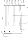
- the device has a first set of data electrodes 31 for the first EL element, a first emitter layer 32 for emitting light of a first wavelength, a first set of strobe electrodes 33 common to the first and second EL elements, a second emitter layer 34 for emitting light of a second wavelength, a bi-functional electrode layer comprising bi-functional electrodes 36, a third emitter layer 37 for emitting light of a third wavelength and a second set of data electrodes 38 for the third EL element.
- the strobe electrodes 33 are perpendicular to the data electrodes 31, so as to define a matrix of pixels in the emitter layer 32 of the first EL element.
- the bi-functional electrodes 36 are perpendicular to the strobe electrodes 33, so as to define a matrix of pixels in the emitter layer 34 of the second EL element.
- the data electrodes 38 are perpendicular to the bi-functional electrodes 36, so as to define a matrix of pixels in the emitter layer 37 for the third EL element.
- the bi-functional electrodes 36 between the second and third emitter layers have to supply both the strobe signal to the third emitter layer and the data signal to the second emitter layer. Again, it would be possible to do this sequentially, but this would have the aforementioned drawbacks.
- the signal applied to the bi-functional electrodes contains the strobe signal for the third EL element within the data signal for the second EL element.
- one of the electrodes (the third from the left in Figure 5) of the bi-functional electrodes 36 is supplied with the select strobe signal for the third EL element.
- the remainder of the bi-functional electrodes 36 are supplied with the data signal for the second EL element.
- the next bi-functional electrode (the fourth from the left in the example of Figure 5) is supplied with the select strobe signal for the third EL element, and so on.
- the select strobe signal for the third EL element is supplied with the select strobe signal for the third EL element, and so on.
- the first and third EL elements are not affected by the driving method of this invention. All pixels of the first and third EL elements are driven normally.
- the strobe signals for the first and second EL elements select a row of pixels
- the strobe signals for the third EL element select a column of pixels. This slightly complicates the addressing scheme when a non-square display is being addressed.
- the address time of the third EL elements would be 67% of the address time for the first and second EL elements. This would have the consequence that, in the signal applied to the bi-functional electrode, the changes in the strobe signal for the third EL element would generally not coincide with changes in the data signal for the second EL element. This would further reduce the effect of the "no-colour-two" pixels on the overall image displayed.
- a 4 x 8 display could be constructed as two separate 4 x 4 displays.
- This method of addressing a display according to the present invention allows one electrode layer to be used to address two EL elements.
- the number of layers required in the device is reduced, compared to a structure in which each EL element has its own strobe and data electrodes (with intermediate insulating layers), so reducing the cost and simplifying the manufacture of the device.
- the addressing method of the present invention allows devices having shared electrode layers to be operated at an increased brightness without requiring an increased driving voltage.
- the strobe voltages and the data voltages must be chosen such that the voltage applied across a non-selected pixel will not switch the pixel to the ON state. In the present invention there is, therefore, an additional constraint on the strobe and data voltages. If it is desired that the "no-colour-2" pixels are in the OFF state, then the strobe voltages applied to the strobe electrode 33 for colours 1 and 2 and the strobe voltages applied to the bi-functional electrodes must be chosen so that they cannot combine to switch the "no-colour-2" pixel to the ON state.
- a preferred set of addressing voltages is as follows: Data voltage for colour one mV to (n + m)V Strobe voltage for colours one and two (n + m)V Data voltage for colour two mV to (n + m)V Strobe voltage for colour three (2n + m)V Data voltage for colour three (n + m)V to (2n + m)V.
- the strobe voltages for the emitter layers for colours 1 and 2 may be either 1 or 0 (arbitrary units), and the data voltages for these emitter layers are also either 0 or 1.
- the strobe voltage applied to a particular pixel in the emitter layer for the first or second colour is 1 and the data voltage is 0, to give a voltage of + 1 across the emitter layer, then the pixel is illuminated. Any other combination of data and strobe voltages give a 0 voltage or a negative voltage across a pixel, and this will not cause the pixel to be illuminated.
- the strobe voltage for the colour 3 emitter layer is always 2, and the data voltage for the colour 3 emitter layer can be either 1 or 2.
- the data voltage is 1, then there is a voltage of + 1 across the pixel, and the pixel is illuminated; when the data voltage is 2, there is no voltage across the pixel and the pixel is not illuminated.
- the data voltages for the colour 2 emitter layer and the colour 3 emitter layer are also chosen so that they cannot combine to switch a pixel in the colour 3 emitter layer to the ON state.
- the data voltages shown in Figure 6 for the emitter layers for colour 2 and 3 satisfy this requirement - they combine to produce only negative or zero voltages across the emitter layer for colour 3.
- an alternative set of preferred addressing voltages is as follows: Data for colour one mV to (2n + m)V Strobe for colours one and two (3n + m)V Data for colour two mV to (2n + m)V Strobe for colour three (4n + m)V Data for colour three (n + m)V to (3n + m)V
- the set of addressing voltages used will depend on the current/voltage characteristics of the EL elements. For example, the addressing voltages shown in Figure 7 would not be suitable for use with EL elements having the current/voltage characteristics shown in Figure 6. This is because the addressing voltages shown in Figure 7 produce a positive voltage across some non-addressed pixels, and these pixels would be switched ON in a EL element having the current/voltage characteristics shown in Figure 6.
- the addressing method of this invention is not limited to use with EL displays but can, in principle, be used to address any device in which two or more elements share a common electrode layer.
- FIG 8 shows the structure of the EL device of Figure 5 in detail.
- the device has a glass substrate 40, on which is deposited an ITO electrode 41 and a semi-transparent Mg:Ag layer 42 (the layers 41 and 42 together correspond to the first data electrodes 31 in the device shown in Figure 5).
- An ETL 43 which is the emitter layer for colour 1 and corresponds to the layer 32 in Figure 5, is grown over the Mg:Ag layer 42, and a HTL 44 is grown on the ETL 43.
- Layer 45 is another ITO electrode layer, over which is grown a further semi-transparent Mg:Ag 46 (the layers 45 and 46 together correspond to the strobe electrode layer 33 in the device of Figure 5).
- ETL 47 which is the emitter layer for colour 2 and corresponds to the emitter layer 34 in Figure 5, is grown and a second HTL is grown over the ETL 47.
- a third ITO electrode 49 is grown over the HTL 48, and this electrode layer corresponds to the bi-functional electrodes 36 of Figure 5.
- a third HTL 50 is grown over the third ITO layer 49.
- a third ETL 51 which forms the emitter layer for colour 3 and corresponds to the emitter layer 37 in the device of Figure 5, is grown over the third HTL 50.
- the device is completed by a Mg:Ag layer 52 which is disposed over the third ETL 51.
- An Ag layer (not shown) can be disposed over the uppermost Mg:Ag layer 52.
- a address generator 53 applies appropriate voltages to the electrode layers 31, 33, 36 and 38.
- the ITO layers are grown on the HTL layers (or on the substrate). These layers are less reactive than Mg:Ag, so that the oxygen present during the sputtering process is less likely to react with the HTL layer and thus be incorporated into the HTL layer during the sputtering process.
- An alternative method of addressing the problem of oxygen reacting with an Mg:Ag layer in the conventional manufacturing method is to use Al:Li electrodes instead of Mg:Ag electrodes.
- Al:Li is a very stable alloy, and so is much less reactive with oxygen than is Mg:Ag.
- the devices described in this application can be manufactured using conventional growth techniques.
Landscapes
- Engineering & Computer Science (AREA)
- Physics & Mathematics (AREA)
- Computer Hardware Design (AREA)
- General Physics & Mathematics (AREA)
- Theoretical Computer Science (AREA)
- Electroluminescent Light Sources (AREA)
- Control Of Indicators Other Than Cathode Ray Tubes (AREA)
- Control Of El Displays (AREA)
Applications Claiming Priority (2)
| Application Number | Priority Date | Filing Date | Title |
|---|---|---|---|
| GB9720604A GB2329740A (en) | 1997-09-30 | 1997-09-30 | A display device and a method of driving a display device |
| GB9720604 | 1997-09-30 |
Publications (1)
| Publication Number | Publication Date |
|---|---|
| EP0905672A1 true EP0905672A1 (de) | 1999-03-31 |
Family
ID=10819746
Family Applications (1)
| Application Number | Title | Priority Date | Filing Date |
|---|---|---|---|
| EP98307759A Withdrawn EP0905672A1 (de) | 1997-09-30 | 1998-09-24 | Mehrschichtige Anzeigetafelkonstruktion und Steuerverfahren dafür |
Country Status (4)
| Country | Link |
|---|---|
| US (1) | US6278417B1 (de) |
| EP (1) | EP0905672A1 (de) |
| JP (1) | JPH11161228A (de) |
| GB (1) | GB2329740A (de) |
Cited By (4)
| Publication number | Priority date | Publication date | Assignee | Title |
|---|---|---|---|---|
| EP1383172A3 (de) * | 2002-07-18 | 2007-01-24 | Tohoku Pioneer Corporation | Organiche elektrolumineszente Anzeigevorrichtung |
| US7403177B2 (en) | 2002-11-29 | 2008-07-22 | Semiconductor Energy Laboratory Co., Ltd. | Display device, driving method thereof, and electronic apparatus |
| US7791571B2 (en) | 2004-04-22 | 2010-09-07 | Semiconductor Energy Laboratory Co., Ltd. | Light emitting device and driving method of the same |
| GB2475026A (en) * | 2009-08-07 | 2011-05-11 | Alessandro Artusi | Display for displaying digital images having improved contrast ratio |
Families Citing this family (9)
| Publication number | Priority date | Publication date | Assignee | Title |
|---|---|---|---|---|
| JP2000075836A (ja) * | 1998-09-02 | 2000-03-14 | Sharp Corp | 有機el発光装置とその駆動方法 |
| JP2001035661A (ja) * | 1999-07-16 | 2001-02-09 | Fuji Photo Film Co Ltd | 多層有機発光素子 |
| US20020036291A1 (en) | 2000-06-20 | 2002-03-28 | Parker Ian D. | Multilayer structures as stable hole-injecting electrodes for use in high efficiency organic electronic devices |
| JP2002299067A (ja) * | 2001-04-03 | 2002-10-11 | Matsushita Electric Ind Co Ltd | El素子及びこれを用いた照光装置 |
| JP4651918B2 (ja) * | 2003-05-21 | 2011-03-16 | 東北パイオニア株式会社 | 有機elパネルの製造方法 |
| US7755275B2 (en) * | 2005-03-28 | 2010-07-13 | Panasonic Corporation | Cascaded light emitting devices based on mixed conductor electroluminescence |
| TWI307978B (en) * | 2006-04-28 | 2009-03-21 | Au Optronics Corp | Cascade organic electroluminescent device |
| US9436056B2 (en) * | 2013-02-06 | 2016-09-06 | E Ink Corporation | Color electro-optic displays |
| CN116171075B (zh) * | 2023-01-31 | 2024-12-06 | 惠科股份有限公司 | 发光器件及其驱动方法、显示面板及其制备方法 |
Citations (3)
| Publication number | Priority date | Publication date | Assignee | Title |
|---|---|---|---|---|
| GB2194376A (en) * | 1986-07-10 | 1988-03-02 | Ricoh Kk | Method of and device for producing multiple colors |
| JPS646398A (en) * | 1987-06-29 | 1989-01-10 | Toshiba Corp | Thin film type multi-color el indicator |
| JPH06302383A (ja) * | 1993-04-16 | 1994-10-28 | Sharp Corp | El素子および液晶表示装置 |
Family Cites Families (7)
| Publication number | Priority date | Publication date | Assignee | Title |
|---|---|---|---|---|
| US4155030A (en) * | 1977-12-19 | 1979-05-15 | International Business Machines Corporation | Multicolor display device using electroluminescent phosphor screen with internal memory and high resolution |
| US4797667A (en) * | 1985-04-30 | 1989-01-10 | Planar Systems, Inc. | Split screen electrode structure for TFEL panel |
| JPS61284091A (ja) * | 1985-06-07 | 1986-12-15 | アルプス電気株式会社 | 薄膜el表示素子 |
| US4691144A (en) * | 1986-01-22 | 1987-09-01 | Planar Systems, Inc. | Staggered refresh pulse generator for a TFEL panel |
| US5416494A (en) * | 1991-12-24 | 1995-05-16 | Nippondenso Co., Ltd. | Electroluminescent display |
| FR2698201B1 (fr) * | 1992-11-13 | 1994-12-16 | Commissariat Energie Atomique | Ecran d'affichage matriciel du type multiplexe et son procédé de commande. |
| US5652600A (en) * | 1994-11-17 | 1997-07-29 | Planar Systems, Inc. | Time multiplexed gray scale approach |
-
1997
- 1997-09-30 GB GB9720604A patent/GB2329740A/en not_active Withdrawn
-
1998
- 1998-09-24 EP EP98307759A patent/EP0905672A1/de not_active Withdrawn
- 1998-09-28 US US09/162,295 patent/US6278417B1/en not_active Expired - Fee Related
- 1998-09-29 JP JP10275740A patent/JPH11161228A/ja not_active Withdrawn
Patent Citations (3)
| Publication number | Priority date | Publication date | Assignee | Title |
|---|---|---|---|---|
| GB2194376A (en) * | 1986-07-10 | 1988-03-02 | Ricoh Kk | Method of and device for producing multiple colors |
| JPS646398A (en) * | 1987-06-29 | 1989-01-10 | Toshiba Corp | Thin film type multi-color el indicator |
| JPH06302383A (ja) * | 1993-04-16 | 1994-10-28 | Sharp Corp | El素子および液晶表示装置 |
Non-Patent Citations (2)
| Title |
|---|
| PATENT ABSTRACTS OF JAPAN vol. 013, no. 176 (E - 749) 25 April 1989 (1989-04-25) * |
| PATENT ABSTRACTS OF JAPAN vol. 095, no. 001 28 February 1995 (1995-02-28) * |
Cited By (6)
| Publication number | Priority date | Publication date | Assignee | Title |
|---|---|---|---|---|
| EP1383172A3 (de) * | 2002-07-18 | 2007-01-24 | Tohoku Pioneer Corporation | Organiche elektrolumineszente Anzeigevorrichtung |
| US7745987B2 (en) | 2002-07-18 | 2010-06-29 | Tohoku Pioneer Corporation | Organic electroluminescent display device |
| US7403177B2 (en) | 2002-11-29 | 2008-07-22 | Semiconductor Energy Laboratory Co., Ltd. | Display device, driving method thereof, and electronic apparatus |
| US7791571B2 (en) | 2004-04-22 | 2010-09-07 | Semiconductor Energy Laboratory Co., Ltd. | Light emitting device and driving method of the same |
| US8497822B2 (en) | 2004-04-22 | 2013-07-30 | Semiconductor Energy Laboratory Co., Ltd. | Light emitting device and driving method of the same |
| GB2475026A (en) * | 2009-08-07 | 2011-05-11 | Alessandro Artusi | Display for displaying digital images having improved contrast ratio |
Also Published As
| Publication number | Publication date |
|---|---|
| GB9720604D0 (en) | 1997-11-26 |
| JPH11161228A (ja) | 1999-06-18 |
| US6278417B1 (en) | 2001-08-21 |
| GB2329740A (en) | 1999-03-31 |
Similar Documents
| Publication | Publication Date | Title |
|---|---|---|
| US7510454B2 (en) | OLED device with improved power consumption | |
| US7091936B1 (en) | Color display device | |
| US6963168B2 (en) | Organic EL display device having certain relationships among constituent element refractive indices | |
| KR100267964B1 (ko) | 유기 이엘(el) 디스플레이 패널 및 그 제조 방법 | |
| JP3884564B2 (ja) | 有機el発光素子およびそれを用いた発光装置 | |
| US8173460B2 (en) | Control circuit for stacked OLED device | |
| US7745987B2 (en) | Organic electroluminescent display device | |
| US20060038752A1 (en) | Emission display | |
| JP3268998B2 (ja) | 表示装置 | |
| GB2337354A (en) | Drive circuit for electroluminescent display providing uniform brightness | |
| US6278417B1 (en) | Method of driving a display device, and a display device | |
| KR20110063087A (ko) | 유기 발광 장치 | |
| US20060181204A1 (en) | Flexible organic light emitting devices | |
| GB2443314A (en) | A method of maufacturing a white light emitting organic EL device | |
| JP3950594B2 (ja) | 表示装置 | |
| JP3672127B2 (ja) | 光学的素子の製造方法及び光学的素子 | |
| EP1538668B1 (de) | Organische elektrolumineszente Vorrichtung | |
| JP2000056732A (ja) | 有機el表示装置 | |
| WO1998059382A1 (en) | Voltage controlled color organic light emitting device and method of producing the same | |
| KR20020062583A (ko) | 유기 전기 발광 소자 | |
| US6614177B2 (en) | Organic light emitting device and method of manufacturing the same | |
| JP2002260858A (ja) | 発光素子及びその製造方法 | |
| JPH11312585A (ja) | 有機el素子 | |
| JP3143350B2 (ja) | 有機エレクトロルミネッセンス素子 | |
| US20100252841A1 (en) | Oled device having improved lifetime and resolution |
Legal Events
| Date | Code | Title | Description |
|---|---|---|---|
| PUAI | Public reference made under article 153(3) epc to a published international application that has entered the european phase |
Free format text: ORIGINAL CODE: 0009012 |
|
| AK | Designated contracting states |
Kind code of ref document: A1 Designated state(s): DE FR GB |
|
| AX | Request for extension of the european patent |
Free format text: AL;LT;LV;MK;RO;SI |
|
| 17P | Request for examination filed |
Effective date: 19990924 |
|
| AKX | Designation fees paid |
Free format text: DE FR GB |
|
| STAA | Information on the status of an ep patent application or granted ep patent |
Free format text: STATUS: THE APPLICATION IS DEEMED TO BE WITHDRAWN |
|
| 18D | Application deemed to be withdrawn |
Effective date: 20061024 |