EP0905713B1 - Structure interne d'une cuve pour réacteur rapide - Google Patents
Structure interne d'une cuve pour réacteur rapide Download PDFInfo
- Publication number
- EP0905713B1 EP0905713B1 EP98307709A EP98307709A EP0905713B1 EP 0905713 B1 EP0905713 B1 EP 0905713B1 EP 98307709 A EP98307709 A EP 98307709A EP 98307709 A EP98307709 A EP 98307709A EP 0905713 B1 EP0905713 B1 EP 0905713B1
- Authority
- EP
- European Patent Office
- Prior art keywords
- reactor
- vessel
- reactor vessel
- core
- coolant
- Prior art date
- Legal status (The legal status is an assumption and is not a legal conclusion. Google has not performed a legal analysis and makes no representation as to the accuracy of the status listed.)
- Expired - Lifetime
Links
Images


Classifications
-
- G—PHYSICS
- G21—NUCLEAR PHYSICS; NUCLEAR ENGINEERING
- G21C—NUCLEAR REACTORS
- G21C11/00—Shielding structurally associated with the reactor
- G21C11/08—Thermal shields; Thermal linings, i.e. for dissipating heat from gamma radiation which would otherwise heat an outer biological shield ; Thermal insulation
- G21C11/088—Thermal shields; Thermal linings, i.e. for dissipating heat from gamma radiation which would otherwise heat an outer biological shield ; Thermal insulation consisting of a stagnant or a circulating fluid
-
- G—PHYSICS
- G21—NUCLEAR PHYSICS; NUCLEAR ENGINEERING
- G21C—NUCLEAR REACTORS
- G21C1/00—Reactor types
- G21C1/02—Fast fission reactors, i.e. reactors not using a moderator ; Metal cooled reactors; Fast breeders
-
- G—PHYSICS
- G21—NUCLEAR PHYSICS; NUCLEAR ENGINEERING
- G21C—NUCLEAR REACTORS
- G21C13/00—Pressure vessels; Containment vessels; Containment in general
- G21C13/02—Details
-
- G—PHYSICS
- G21—NUCLEAR PHYSICS; NUCLEAR ENGINEERING
- G21C—NUCLEAR REACTORS
- G21C15/00—Cooling arrangements within the pressure vessel containing the core; Selection of specific coolants
- G21C15/02—Arrangements or disposition of passages in which heat is transferred to the coolant; Coolant flow control devices
- G21C15/12—Arrangements or disposition of passages in which heat is transferred to the coolant; Coolant flow control devices from pressure vessel; from containment vessel
-
- Y—GENERAL TAGGING OF NEW TECHNOLOGICAL DEVELOPMENTS; GENERAL TAGGING OF CROSS-SECTIONAL TECHNOLOGIES SPANNING OVER SEVERAL SECTIONS OF THE IPC; TECHNICAL SUBJECTS COVERED BY FORMER USPC CROSS-REFERENCE ART COLLECTIONS [XRACs] AND DIGESTS
- Y02—TECHNOLOGIES OR APPLICATIONS FOR MITIGATION OR ADAPTATION AGAINST CLIMATE CHANGE
- Y02E—REDUCTION OF GREENHOUSE GAS [GHG] EMISSIONS, RELATED TO ENERGY GENERATION, TRANSMISSION OR DISTRIBUTION
- Y02E30/00—Energy generation of nuclear origin
- Y02E30/30—Nuclear fission reactors
Definitions
- top-entry type top-feed and top-discharge type
- cold and hot leg pipings are inserted from an upper portion of a reactor vessel
- the dip plate suspension structure cannot be employed, since the pipings of a primary main cooling system are inserted from an upper portion of the reactor vessel, and a plurality of pipings extend between the free liquid surface and the upper shielding member.
- a construction has been proposed in which a flow guide structure comprising a horizontal ring plate of a large width extending over the whole inner circumferential surface of a reactor vessel, and a cylindrical perforated plate extending downward from an inner edge of the ring plate is provided (refer to "Study on Flow Optimization in Reactor Vessel of Top-Entry Loop-Type DFBR", ICONE-3 (3rd International Conference on Nuclear Engineering) vol. 1, Kyoto, Japan (April 1995)).
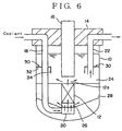
- FIG. 6 Such a top-entry type fast reactor is shown schematically in Fig. 6.
- a reactor core 12 is positioned in the interior of a reactor vessel 10, and an upper opening of the reactor vessel 10 is closed with a shielding plug 14, to which an upper core structure 16 is fixed.
- the upper core structure 16 includes therein various instrumentation devices and supporting members of a control rod-driving mechanism (not shown).
- a cold leg piping 18 is introduced from an upper opening of the reactor vessel 10 into a high-pressure plenum 20, while a hot leg piping 22 is led out from an upper plenum 24 so as to pass through the upper opening.
- a coolant sodium is supplied from the cold leg piping 18, enters the high-pressure plenum 20, and passes through a low-pressure plenum 26 to reach the core 12, in which the coolant sodium is heated.
- the heated coolant sodium flows out from a core outlet surface 12a into the upper plenum 24, and further flows through the hot leg piping 22 to reach an intermediate heat exchanger (not shown) disposed outside the reactor vessel.
- a part of the coolant sodium passing through the low-pressure plenum 26 flows out to an intermediate plenum 28.
- a flow guide structure 30 is provided in the interior of the upper plenum 24.
- This flow guide structure 30 comprises a horizontal ring plate 32 of a large width provided so as to extend over the whole inner circumferential surface of the reactor vessel, and a cylindrical perforated plate 34 extending downward from an inner edge of the ring plate 32.
- the width of the ring plate 32 is set broadly so that it becomes not less than a half of a distance between the inner circumferential surface of the reactor vessel 10 and the outer circumferential surface of the upper core structure 16.
- Diameter of the reactor vessel 9.88 m Diameter of the upper core structure 2.85 m Height of the free liquid surface 6.10 m Position of the annular plate 2.94 m below the free liquid surface Width of the ring plate 2.00 m Height of the cylindrical perforated plate 1.00 m
- the flow guide structure 30 comprising the ring plate and cylindrical perforated plate cannot prevent the sloshing of the coolant at the free liquid surface 50 during an earthquake, and it is also difficult to prevent the fluctuation of the liquid surface accompanied by the thermal shrinkage of the coolant (liquid level change) at the time of the plant tripping.
- the present invention is directed to an in-vessel structure for a top-entry type fast reactor comprising a reactor core disposed in a reactor vessel; an upper core structure disposed above the core; an upper plenum occupied in the upper portion of the reactor vessel above the core, a free liquid surface of a coolant being in the upper plenum; a cold leg piping inserted into the reactor vessel from the top thereof and led to the core; and a hot leg piping extended from the upper plenum to the outside of the reactor vessel through the top thereof; the coolant being introduced through the cold leg piping to the core in which it is heated, then flowing out from the core into the upper plenum and being discharging through the hot leg piping to the outside of the reactor vessel, and is characterised in that a plurality of annular fins are fixed horizontally in an axially spaced manner to both the portions of an outer circumferential surface of the upper core structure and the opposite portions of an inner circumferential surface of the reactor vessel, said portions being under the free liquid surface during a rated
- the annular fins fixed to both the upper core structure and the reactor vessel are respectively provided in a plurality of axially spaced stages.
- the width of each of the annular fins is as small as around 5 to 15% of a distance between the inner circumferential surface of the reactor vessel and the outer circumferential surface of the upper core structure.
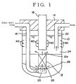
- Fig. 1 shows an example of an in-vessel structure for a fast reactor according to the present invention. Since the basic reactor construction is substantially identical with that of the prior art described hereinbefore, the corresponding parts are designated by the same reference numerals so as to have the description of the present invention easily understood.
- a reactor core 12 is positioned in the interior of a reactor vessel 10, and an upper opening of the reactor vessel 10 is closed with a shielding plug 14.
- An upper core structure 16 is fixed to the shielding plug 14, and a cold leg piping 18 is introduced from an upper portion of the reactor vessel 10 into a high-pressure plenum 20, while a hot leg piping 22 is led out to the outside of the upper portion of the reactor vessel 10.
- a plurality of (for example, three) primary main cooling systems each of which includes the cold and hot leg pipings 18 and 22, are usually provided, so that three cold leg pipings 18 and three hot leg pipings 22 are incorporated.
- four heat exchangers (DHX) of an auxiliary direct core cooling system (not shown) are provided.
- the coolant sodium is supplied from the cold leg piping 18 to a high-pressure plenum 20, and passes through a low-pressure plenum 26 to reach the core 12, in which it is heated.
- the heated cooling sodium flows out from a core outlet surface 12a into an upper plenum 24, and reaches an intermediate heat exchanger (not shown) outside the reactor vessel through the hot leg piping 22.
- a part of the coolant sodium passing through the low-pressure plenum 26 flows out to an intermediate plenum 28.
- a plurality of (three in this embodiment) annular fins 40 are fixed horizontally, in a substantially equally spaced manner in the axial (i.e., vertical) direction, to both the portions of an outer circumferential surface of the upper core structure 16 and the opposite portions of an inner circumferential surface of the reactor vessel 10. These portions are under the free liquid surface formed when the reactor is in a rated operation.
- Each annular fin 40 in this embodiment is completely continuous over the whole circumference thereof, and set to a width around 10% of a distance between the inner circumferential surface of the reactor vessel 10 and the outer circumferential surface of the upper core structure 16.
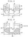
- Fig. 2 shows the flow pattern in the fast reactor during the rated operation.
- the high-velocity coolant flowing out from the core outlet surface 12a impinges upon a lower surface of the upper core structure 16 to form a diagonal flow advancing toward the reactor vessel wall.
- this diagonal flow turns into an upward flow along the reactor vessel wall, a further upward movement thereof is stopped by the annular fins 40 provided on the reactor vessel 10.
- the upward flow fails to further move up and turns into vortexes in a region below the free liquid surface 50.
- the inner flow cannot reach the free liquid surface 50, and the fluctuation of the liquid surface is thereby prevented.
- the vortexes comprising a surplus upward flow which cannot be stopped by the annular fins provided on the reactor vessel wall are restrained by the annular fins 40 provided on the outer circumferential surface of the upper core structure 16. Owing to a combination of these effects, the fluctuation of the liquid surface 50 is effectively minimized.
- Fig. 3 is an explanatory view showing a case where the emergency shutdown (plant tripping) of the reactor occurs.
- the low-temperature sodium flows out at a low flow velocity from the core outlet surface 12a, the heat transition to the primary main cooling system can be lessened since substantially the whole region of the interior of the upper plenum 24 can be utilized as an effective mixing space.
- the early elimination of a thermal stratification interface 60 can be effected since substantially the whole region of the interior of the upper plenum 24 can similarly be utilized as an effective mixing space.
- Fig. 5 shows an in-vessel flow of the coolant in a case where the free liquid surface 50 lowers with an earthquake occurring. Even when the free liquid surface 50 lowers, some annular fins 40 in lower stages out of a plurality thereof are kept immersed in the coolant. Therefore, the fluctuation (sloshing) of the free liquid surface can be effectively lessened.
- the annular fins 40 are formed continuously over the whole circumference of the reactor vessel 10, i.e., they are formed like complete rings but they may not necessarily be completely continuous over the whole circumference of the reactor vessel. Namely, each of the annular fins may comprise a certain number of arcuate parts arranged in the same plane in a slightly space manner. When such discontinuous annular fins are used, the clearances among the arcuate parts in one stage shall not be aligned with those among the arcuate parts in an adjacent stage, e.g., the arcuate parts shall be arranged in a half interval staggered manner.
- the inner flow of the coolant advancing upward along the reactor vessel wall is stopped, whereby the sloshing of the free liquid surface can be effectively prevented.
- This enables the gas entrainment in the coolant which is ascribed to the sloshing of the free liquid surface to be prevented, and the safety of an operation of the fast reactor to be secured.
- the excessive heat transition to the primary main cooling system can be lessened and the early elimination of a thermal stratification interface at the time of occurrence of a thermal stratification phenomenon can be effected.
Landscapes
- Engineering & Computer Science (AREA)
- Physics & Mathematics (AREA)
- Plasma & Fusion (AREA)
- General Engineering & Computer Science (AREA)
- High Energy & Nuclear Physics (AREA)
- Health & Medical Sciences (AREA)
- Life Sciences & Earth Sciences (AREA)
- Biomedical Technology (AREA)
- General Health & Medical Sciences (AREA)
- Molecular Biology (AREA)
- Structure Of Emergency Protection For Nuclear Reactors (AREA)
Claims (2)
- Structure de cuve interne pour un réacteur rapide, comprenant :dans laquelle le réfrigérant est introduit par ladite tuyauterie de branche froide (18) jusque dans ledit coeur (12) où il est chauffé, après quoi il s'écoule hors dudit coeur (12) dans ledit plénum supérieur (24), et est refoulé par ladite tuyauterie de branche chaude (22) vers l'extérieur de la cuve du réacteur (10) ;Un coeur de réacteur (12) disposé dans une cuve de réacteur (10) ; une structure de coeur supérieure (16) disposée au-dessus dudit coeur (12) ; un plénum supérieur (24) occupant la partie supérieure de ladite cuve du réacteur (10) au-dessus dudit coeur (12) ; une surface de liquide libre (50) d'un réfrigérant se trouvant dans ledit plénum supérieur (24) ; une tuyauterie de branche froide (18) insérée dans ladite cuve de réacteur (10) depuis le sommet de celle-ci et allant jusqu'au coeur (12) ; et une tuyauterie de branche chaude (22) allant dudit plénum supérieur (24) jusqu'à l'extérieur de ladite cuve du réacteur en passant par le sommet de celle-ci ;
caractérisée en ce que plusieurs ailettes annulaires (40) sont fixées horizontalement et espacées axialement sur des parties de la surface circonférentielle externe de ladite structure de coeur supérieure (16) ainsi que sur des parties opposées de la surface circonférentielle interne de ladite cuve du réacteur (10), lesdites parties se trouvant sous ladite surface de liquide libre (50) pendant le fonctionnement nominal dudit réacteur. - Structure de cuve interne pour un réacteur rapide selon la revendication 1, dans laquelle lesdites ailettes annulaires (40) sont disposées en plusieurs étages espacés axialement, respectivement, la largeur de chacune des ailettes annulaires (40) représentant de 5 à 15 % de la distance entre la surface circonférentielle interne de ladite cuve du réacteur (10) et la surface circonférentielle externe de ladite structure de coeur supérieure (16).
Applications Claiming Priority (3)
| Application Number | Priority Date | Filing Date | Title |
|---|---|---|---|
| JP28133297 | 1997-09-29 | ||
| JP9281332A JP2923270B2 (ja) | 1997-09-29 | 1997-09-29 | 高速炉の炉内構造 |
| JP281332/97 | 1997-09-29 |
Publications (2)
| Publication Number | Publication Date |
|---|---|
| EP0905713A1 EP0905713A1 (fr) | 1999-03-31 |
| EP0905713B1 true EP0905713B1 (fr) | 2005-11-23 |
Family
ID=17637637
Family Applications (1)
| Application Number | Title | Priority Date | Filing Date |
|---|---|---|---|
| EP98307709A Expired - Lifetime EP0905713B1 (fr) | 1997-09-29 | 1998-09-23 | Structure interne d'une cuve pour réacteur rapide |
Country Status (4)
| Country | Link |
|---|---|
| US (1) | US5940463A (fr) |
| EP (1) | EP0905713B1 (fr) |
| JP (1) | JP2923270B2 (fr) |
| DE (1) | DE69832452T2 (fr) |
Families Citing this family (4)
| Publication number | Priority date | Publication date | Assignee | Title |
|---|---|---|---|---|
| KR100560208B1 (ko) * | 2002-03-12 | 2006-03-10 | 에스케이씨 주식회사 | 상온에서 겔화가능한 겔 고분자 전해질용 조성물 |
| US8638901B2 (en) | 2010-12-29 | 2014-01-28 | Westinghouse Electric Company Llc | Optimum configuration for fast reactors |
| JP5959043B2 (ja) * | 2012-01-17 | 2016-08-02 | 三菱Fbrシステムズ株式会社 | 高速増殖炉原子炉容器内上部プレナム内整流装置 |
| US10535436B2 (en) * | 2014-01-14 | 2020-01-14 | Ge-Hitachi Nuclear Energy Americas Llc | Nuclear reactor chimney and method of improving core inlet enthalpy using the same |
Family Cites Families (2)
| Publication number | Priority date | Publication date | Assignee | Title |
|---|---|---|---|---|
| US5043135A (en) * | 1989-05-18 | 1991-08-27 | General Electric Company | Method for passive cooling liquid metal cooled nuclear reactors, and system thereof |
| JPH07248389A (ja) * | 1994-03-09 | 1995-09-26 | Toshiba Corp | 高速炉 |
-
1997
- 1997-09-29 JP JP9281332A patent/JP2923270B2/ja not_active Expired - Fee Related
-
1998
- 1998-08-28 US US09/143,439 patent/US5940463A/en not_active Expired - Lifetime
- 1998-09-23 DE DE69832452T patent/DE69832452T2/de not_active Expired - Lifetime
- 1998-09-23 EP EP98307709A patent/EP0905713B1/fr not_active Expired - Lifetime
Also Published As
| Publication number | Publication date |
|---|---|
| DE69832452D1 (de) | 2005-12-29 |
| US5940463A (en) | 1999-08-17 |
| DE69832452T2 (de) | 2006-08-03 |
| EP0905713A1 (fr) | 1999-03-31 |
| JP2923270B2 (ja) | 1999-07-26 |
| JPH11101886A (ja) | 1999-04-13 |
Similar Documents
| Publication | Publication Date | Title |
|---|---|---|
| KR960008856B1 (ko) | 역류 냉각제 흐름로를 갖는 액상금속 냉각 원자로에 대한 수동 냉각 시스템 | |
| US3962032A (en) | Fast nuclear reactor | |
| US5043136A (en) | Passive cooling safety system for liquid metal cooled nuclear reactors | |
| US5000907A (en) | Nuclear reactor with emergency cooling water injection device | |
| EP4022650B1 (fr) | Réacteurs à combustible en fusion et plaques annulaires à orifices pour réacteurs à combustible en fusion | |
| EP2194534B1 (fr) | Réacteur nucléaire | |
| US4959193A (en) | Indirect passive cooling system for liquid metal cooled nuclear reactors | |
| JPS5916238B2 (ja) | 原子炉の緊急冷却装置 | |
| EP3127122B1 (fr) | Ensemble combustible nucléaire à faible chute de pression | |
| US5021211A (en) | Liquid metal cooled nuclear reactors with passive cooling system | |
| US5158741A (en) | Passive cooling system for top entry liquid metal cooled nuclear reactors | |
| EP0905713B1 (fr) | Structure interne d'une cuve pour réacteur rapide | |
| US3366547A (en) | Fast nuclear reactor | |
| US3379616A (en) | Heat extraction device for nuclear reactor | |
| US5857006A (en) | Chimney for enhancing flow of coolant water in natural circulation boiling water reactor | |
| GB1582107A (en) | Nuclear reactor | |
| JP7440385B2 (ja) | 燃料集合体 | |
| JP2972162B2 (ja) | 高速炉の炉壁冷却保護構造 | |
| US4879089A (en) | Liquid metal cooled nuclear reactors | |
| Ventre | Nuclear reactor with integrated heat exchanger | |
| JPH01185485A (ja) | 原子炉容器の熱保護装置 | |
| JPH04294295A (ja) | タンク型高速増殖炉 | |
| JPH03277994A (ja) | タンク型高速増殖炉 | |
| JPS63279198A (ja) | 原子炉 | |
| JPH01217292A (ja) | タンク型原子炉 |
Legal Events
| Date | Code | Title | Description |
|---|---|---|---|
| PUAI | Public reference made under article 153(3) epc to a published international application that has entered the european phase |
Free format text: ORIGINAL CODE: 0009012 |
|
| AK | Designated contracting states |
Kind code of ref document: A1 Designated state(s): DE FR GB |
|
| AX | Request for extension of the european patent |
Free format text: AL;LT;LV;MK;RO;SI |
|
| RAP1 | Party data changed (applicant data changed or rights of an application transferred) |
Owner name: JAPAN NUCLEAR CYCLE DEVELOPMENT INSTITUTE |
|
| 17P | Request for examination filed |
Effective date: 19990324 |
|
| AKX | Designation fees paid |
Free format text: DE FR GB |
|
| GRAP | Despatch of communication of intention to grant a patent |
Free format text: ORIGINAL CODE: EPIDOSNIGR1 |
|
| GRAS | Grant fee paid |
Free format text: ORIGINAL CODE: EPIDOSNIGR3 |
|
| GRAA | (expected) grant |
Free format text: ORIGINAL CODE: 0009210 |
|
| AK | Designated contracting states |
Kind code of ref document: B1 Designated state(s): DE FR GB |
|
| REG | Reference to a national code |
Ref country code: GB Ref legal event code: FG4D |
|
| REF | Corresponds to: |
Ref document number: 69832452 Country of ref document: DE Date of ref document: 20051229 Kind code of ref document: P |
|
| ET | Fr: translation filed | ||
| PLBE | No opposition filed within time limit |
Free format text: ORIGINAL CODE: 0009261 |
|
| STAA | Information on the status of an ep patent application or granted ep patent |
Free format text: STATUS: NO OPPOSITION FILED WITHIN TIME LIMIT |
|
| 26N | No opposition filed |
Effective date: 20060824 |
|
| PGFP | Annual fee paid to national office [announced via postgrant information from national office to epo] |
Ref country code: GB Payment date: 20110920 Year of fee payment: 14 Ref country code: FR Payment date: 20110928 Year of fee payment: 14 Ref country code: DE Payment date: 20110923 Year of fee payment: 14 |
|
| GBPC | Gb: european patent ceased through non-payment of renewal fee |
Effective date: 20120923 |
|
| REG | Reference to a national code |
Ref country code: FR Ref legal event code: ST Effective date: 20130531 |
|
| PG25 | Lapsed in a contracting state [announced via postgrant information from national office to epo] |
Ref country code: DE Free format text: LAPSE BECAUSE OF NON-PAYMENT OF DUE FEES Effective date: 20130403 Ref country code: GB Free format text: LAPSE BECAUSE OF NON-PAYMENT OF DUE FEES Effective date: 20120923 |
|
| PG25 | Lapsed in a contracting state [announced via postgrant information from national office to epo] |
Ref country code: FR Free format text: LAPSE BECAUSE OF NON-PAYMENT OF DUE FEES Effective date: 20121001 |
|
| REG | Reference to a national code |
Ref country code: DE Ref legal event code: R119 Ref document number: 69832452 Country of ref document: DE Effective date: 20130403 |