EP0905728A2 - Dispositif pour commander une serrure électrique pour portière d'un véhicule automobile - Google Patents
Dispositif pour commander une serrure électrique pour portière d'un véhicule automobile Download PDFInfo
- Publication number
- EP0905728A2 EP0905728A2 EP98117946A EP98117946A EP0905728A2 EP 0905728 A2 EP0905728 A2 EP 0905728A2 EP 98117946 A EP98117946 A EP 98117946A EP 98117946 A EP98117946 A EP 98117946A EP 0905728 A2 EP0905728 A2 EP 0905728A2
- Authority
- EP
- European Patent Office
- Prior art keywords
- frame
- pushbutton switch
- lateral portion
- seat
- elongated body
- Prior art date
- Legal status (The legal status is an assumption and is not a legal conclusion. Google has not performed a legal analysis and makes no representation as to the accuracy of the status listed.)
- Withdrawn
Links
Images
Classifications
-
- H—ELECTRICITY
- H01—ELECTRIC ELEMENTS
- H01H—ELECTRIC SWITCHES; RELAYS; SELECTORS; EMERGENCY PROTECTIVE DEVICES
- H01H13/00—Switches having rectilinearly-movable operating part or parts adapted for pushing or pulling in one direction only, e.g. push-button switch
- H01H13/02—Details
- H01H13/12—Movable parts; Contacts mounted thereon
- H01H13/14—Operating parts, e.g. push-button
-
- H—ELECTRICITY
- H01—ELECTRIC ELEMENTS
- H01H—ELECTRIC SWITCHES; RELAYS; SELECTORS; EMERGENCY PROTECTIVE DEVICES
- H01H3/00—Mechanisms for operating contacts
- H01H3/02—Operating parts, i.e. for operating driving mechanism by a mechanical force external to the switch
- H01H3/12—Push-buttons
- H01H3/122—Push-buttons with enlarged actuating area, e.g. of the elongated bar-type; Stabilising means therefor
Definitions
- the present invention relates to a device for controlling an electric vehicle door lock.
- the present invention relates to a control device of the type comprising a supporting frame fitted directly to a vehicle door; a pushbutton switch; and means for manually operating the pushbutton switch.
- a device for controlling an electric lock of a vehicle door comprising a respective supporting frame fitted directly to a vehicle door, a pushbutton switch fitted to the frame, and manual operating means for manually operating the pushbutton switch; characterized in that said manual operating means comprise a single elongated body at least partially deformable elastically and which acts directly on said pushbutton switch; relatively-movable means being provided to fit said elongated body to said frame.
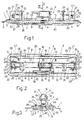
- Number 1 in Figures 1 and 3 indicates as a whole a vehicle door, the body 2 of which comprises an opening 3 through which extends a device 4 for operating an electric lock (not shown) of door 1.
- Device 4 comprises a respective elongated frame 5 having a respective longitudinal axis 6 and in turn comprising an elongated annular plate 7.
- Plate 7 comprises two longitudinal portions 8 facing each other and parallel to axis 6; and two transverse portions 9 facing each other, extending perpendicular to axis 6, and defining, together with longitudinal portions 8, a rectangular opening 10 extending along axis 6 ( Figures 2 and 3).
- Frame 5 also comprises- a bracket 12 for supporting a known pushbutton switch 13, which is oriented with an axis 14 coincident with an activating direction of switch 13, perpendicular to axis 6, and intersecting axis 6 at a point P substantially equidistant from transverse portions 9 and from longitudinal portions 8. More specifically, bracket 12 defines a click-in seat 15 for switch 13, which is clicked into seat 15 through a lateral opening 16. Inside seat 15, switch 13 is maintained in a fixed position by a pair of pins 18, which extend inside seat 15 perpendicularly to axes 6 and 14, and each engage a respective through hole 19 in switch 13.
- frame 5 also comprises, for each transverse portion 9, a pair of facing elastic walls 21 integral with respective portion 9 and extending parallel to and on opposite sides of a plane containing axes 6 and 14.
- Walls 21 in each pair define a respective seat 22 for a respective end portion 23 of an elongated body 24 made of plastic material and also comprising an elongated intermediate portion 25, which extends at opening 10 and in a raised position with respect to plate 7, and which, in use, cooperates directly with, to operate or activate, switch 13.
- Each portion 23 of body 24 is connected to the respective pair of walls 21 by a respective click-in connecting assembly 26 comprising, for each respective wall 21, a slot 27 parallel to axis 14 and facing the slot 27 in the other wall 21 in the same pair.
- the slots 27 formed in walls 21 in the same pair are engaged by respective pins 28, which are integral with respective portion 23, extend coaxially with a common axis 29 perpendicular to axes 6 and 14, and engage respective slots 27 in sliding manner in directions parallel to axis 14 and in rotary manner about common axis 29 to define, together with the respective walls, a hinge with a hinge axis movable crosswise to itself.
- Each pin 28 is defined axially by a respective inclined front surface 30, which, when fitting body 24 to frame 5, cooperates in sliding manner with a respective inclined lead-in surface internally defining respective wall 21, to enable pin 28 to click into and remain inside slot 27.
- each portion 23 carries a respective integral elastic blade 32, which projects towards switch 13, is positioned facing and parallel to portion 25, and is separated transversely from portion 25 on the same side as switch 13.
- Each blade 32 has a respective cylindrical end portion 33 contacting a respective stop surface internally defining one arm of a respective L-shaped bracket 34, the other arm of which is integral with plate 7, and extends perpendicularly to plate 7 on the same side as walls 21.
- plate 7 of frame 5 is covered partly by a hood-type seal 36 comprising an intermediate portion 37 covering the surface of plate 7 facing outwards in use, and a peripheral annular portion 38. More specifically, intermediate portion 37 extends on the opposite side of plate 7 to body 24, and comprises a pair of opposite elongated longitudinal projections 39 and 40 (Figure 3); projection 39 projects inwards of seal 36 through opening 10, loosely engages opening 10, and, in use, directly contacts portion 25 of body 24; while projection 40 projects outwards, and is defined by a cylindrical lateral surface acted on by the user to open the lock (not shown).
- Annular portion 38 of seal 36 extends between plate 7 and body 2, and is gripped between plate 7 and body 2 by means of an assembly 42 for clicking frame 5 onto body 2 ( Figure 3).
- assembly 42 comprises an elongated anchoring element 43, which is integral with plate 7, extends parallel to axis 6 through opening 3 in body 2, and is anchored to body 2; and a click-on appendix 44, which is also integral with plate 7, extends through opening 3 on the opposite side of body 24 to anchoring element 43, and terminates with a tooth clicked onto body 2.
- device 4 as described is therefore extremely straightforward to produce and quick to assemble. This is mainly due to switch 13 of device 4 being activated by a single body 24 made in one piece from plastic material and supporting integral elastic reaction elements, and by sliding body 24 along axis 6 and parallel to plate 7, so that portions 23 of body 24 slide between respective walls 21, and pins 28 click inside respective slots 27.
- body 24 Unlike known solutions, the design characteristics of body 24 and the particular way in which body 24 is connected to frame 5 also enable switch 13 to be activated by pressing any portion of projection 40. That is, if pressure is applied by the user at point P, portion 25 of body 24 simply translates parallel to itself along axis 14, by both blades 32 being subjected to the same bending moment. Conversely, if pressure is applied on or close to one of hinge axes 29, portion 25 practically only rotates about the other hinge axis 29. In all the other intermediate conditions, portion 25 rotates and translates towards switch 13.
- device 4 as described is therefore also highly reliable, which is further enhanced by the particular design of seal 36 and by permanent sealing of the frame-body connection.
Landscapes
- Lock And Its Accessories (AREA)
- Push-Button Switches (AREA)
Applications Claiming Priority (2)
| Application Number | Priority Date | Filing Date | Title |
|---|---|---|---|
| ITTO970833 | 1997-09-23 | ||
| ITTO970833 IT1294880B1 (it) | 1997-09-23 | 1997-09-23 | Dispositivo per il comando di una serratura elettrica per una porta di un veicolo. |
Publications (2)
| Publication Number | Publication Date |
|---|---|
| EP0905728A2 true EP0905728A2 (fr) | 1999-03-31 |
| EP0905728A3 EP0905728A3 (fr) | 2000-01-05 |
Family
ID=11416013
Family Applications (1)
| Application Number | Title | Priority Date | Filing Date |
|---|---|---|---|
| EP98117946A Withdrawn EP0905728A3 (fr) | 1997-09-23 | 1998-09-22 | Dispositif pour commander une serrure électrique pour portière d'un véhicule automobile |
Country Status (2)
| Country | Link |
|---|---|
| EP (1) | EP0905728A3 (fr) |
| IT (1) | IT1294880B1 (fr) |
Family Cites Families (3)
| Publication number | Priority date | Publication date | Assignee | Title |
|---|---|---|---|---|
| DE3405654C2 (de) * | 1984-02-17 | 1996-02-29 | Asea Brown Boveri | Betätigungsvorrichtung für Schalteinrichtungen |
| US5247143A (en) * | 1990-03-09 | 1993-09-21 | Canon Kabushiki Kaisha | Key switch |
| DE4443117B4 (de) * | 1994-12-02 | 2005-03-03 | Ewald Witte Gmbh & Co Kg | In eine Öffnung einer Tür, insbesondere Kraftfahrzeug-Tür einsetzbarer Griffbeschlag |
-
1997
- 1997-09-23 IT ITTO970833 patent/IT1294880B1/it active IP Right Grant
-
1998
- 1998-09-22 EP EP98117946A patent/EP0905728A3/fr not_active Withdrawn
Also Published As
| Publication number | Publication date |
|---|---|
| ITTO970833A1 (it) | 1999-03-23 |
| EP0905728A3 (fr) | 2000-01-05 |
| IT1294880B1 (it) | 1999-04-23 |
Similar Documents
| Publication | Publication Date | Title |
|---|---|---|
| EP0632529B1 (fr) | Connecteur à ressort de blocage | |
| US20200153125A9 (en) | Conductor terminal and method for mounting the same | |
| US20190237904A1 (en) | Electrical plug connection | |
| AU8055191A (en) | Improvements in or relating to electrical connectors | |
| US4684768A (en) | Resilient sectional strip for mounting to a closure edge | |
| CN116113745B (zh) | 用于处理机的防护组件的闩锁机构 | |
| US5389752A (en) | Switch control lever | |
| US20230420200A1 (en) | Module for Generating Opening Signals | |
| CN115939790A (zh) | 连接装置、连接端子和电子设备 | |
| EP1050640B1 (fr) | Poignée de porte de véhicule automobile | |
| CN100456404C (zh) | 小型开关 | |
| EP0903453A2 (fr) | Poignée de porte pour véhicules | |
| EP0905728A2 (fr) | Dispositif pour commander une serrure électrique pour portière d'un véhicule automobile | |
| US20230417087A1 (en) | Module for Generating Opening Signals | |
| EP1128002A2 (fr) | Poignée de porte pour véhicule | |
| US5642806A (en) | Rocker actuated switch assembly | |
| EP0903454A2 (fr) | Poignée pour porte de véhicule | |
| EP1137038A3 (fr) | Unité d'arbre de commande pour un interrupteur | |
| WO2004057135A3 (fr) | Commutateur presentant des moyens de retour elastique pour portes ou coffres de vehicules | |
| US20070062796A1 (en) | Electric switch | |
| US5860516A (en) | Electric switch assembly | |
| GB2308156A (en) | Microwave oven door:opening mechanism | |
| EP0736886A2 (fr) | Dispositif électronique de sécurité en particulier pour appareil de jardinage | |
| EP0999323A2 (fr) | Poignée pour le contrôle d'une serrure de véhicule électrique | |
| US5661274A (en) | Precision double-pole single-throw switch assembly |
Legal Events
| Date | Code | Title | Description |
|---|---|---|---|
| PUAI | Public reference made under article 153(3) epc to a published international application that has entered the european phase |
Free format text: ORIGINAL CODE: 0009012 |
|
| AK | Designated contracting states |
Kind code of ref document: A2 Designated state(s): DE ES FR GB |
|
| AX | Request for extension of the european patent |
Free format text: AL;LT;LV;MK;RO;SI |
|
| PUAL | Search report despatched |
Free format text: ORIGINAL CODE: 0009013 |
|
| AK | Designated contracting states |
Kind code of ref document: A3 Designated state(s): AT BE CH CY DE DK ES FI FR GB GR IE IT LI LU MC NL PT SE |
|
| AX | Request for extension of the european patent |
Free format text: AL;LT;LV;MK;RO;SI |
|
| 17P | Request for examination filed |
Effective date: 20000617 |
|
| AKX | Designation fees paid |
Free format text: DE ES FR GB |
|
| GRAP | Despatch of communication of intention to grant a patent |
Free format text: ORIGINAL CODE: EPIDOSNIGR1 |
|
| STAA | Information on the status of an ep patent application or granted ep patent |
Free format text: STATUS: THE APPLICATION IS DEEMED TO BE WITHDRAWN |
|
| 18D | Application deemed to be withdrawn |
Effective date: 20031211 |