EP0906052B1 - Optischer koppler für eine optische untersuchungsvorrichtung - Google Patents
Optischer koppler für eine optische untersuchungsvorrichtung Download PDFInfo
- Publication number
- EP0906052B1 EP0906052B1 EP96921808A EP96921808A EP0906052B1 EP 0906052 B1 EP0906052 B1 EP 0906052B1 EP 96921808 A EP96921808 A EP 96921808A EP 96921808 A EP96921808 A EP 96921808A EP 0906052 B1 EP0906052 B1 EP 0906052B1
- Authority
- EP
- European Patent Office
- Prior art keywords
- fibers
- optical
- optical coupler
- coupler device
- light
- Prior art date
- Legal status (The legal status is an assumption and is not a legal conclusion. Google has not performed a legal analysis and makes no representation as to the accuracy of the status listed.)
- Expired - Lifetime
Links
- 230000003287 optical effect Effects 0.000 title claims abstract description 91
- 239000000835 fiber Substances 0.000 claims abstract description 179
- 238000012544 monitoring process Methods 0.000 claims abstract description 10
- 210000001519 tissue Anatomy 0.000 claims description 37
- 239000013307 optical fiber Substances 0.000 claims description 30
- 210000003128 head Anatomy 0.000 claims description 24
- 230000008878 coupling Effects 0.000 claims description 23
- 238000010168 coupling process Methods 0.000 claims description 23
- 238000005859 coupling reaction Methods 0.000 claims description 23
- 210000004209 hair Anatomy 0.000 claims description 18
- 210000004556 brain Anatomy 0.000 claims description 16
- 210000000481 breast Anatomy 0.000 claims description 16
- 230000001681 protective effect Effects 0.000 claims description 12
- 239000002872 contrast media Substances 0.000 claims description 9
- 210000004761 scalp Anatomy 0.000 claims description 8
- 230000000740 bleeding effect Effects 0.000 claims description 4
- 238000001727 in vivo Methods 0.000 claims description 4
- 239000004033 plastic Substances 0.000 claims description 4
- 229920003023 plastic Polymers 0.000 claims description 4
- 210000003625 skull Anatomy 0.000 claims description 4
- 238000012546 transfer Methods 0.000 claims description 4
- 239000006096 absorbing agent Substances 0.000 claims 1
- 230000002093 peripheral effect Effects 0.000 claims 1
- 239000000523 sample Substances 0.000 description 24
- 238000001514 detection method Methods 0.000 description 16
- 238000003384 imaging method Methods 0.000 description 14
- 238000002595 magnetic resonance imaging Methods 0.000 description 13
- 206010018852 Haematoma Diseases 0.000 description 8
- 230000005540 biological transmission Effects 0.000 description 6
- FVAUCKIRQBBSSJ-UHFFFAOYSA-M sodium iodide Chemical compound [Na+].[I-] FVAUCKIRQBBSSJ-UHFFFAOYSA-M 0.000 description 6
- LRUUNMYPIBZBQH-UHFFFAOYSA-N Methazole Chemical compound O=C1N(C)C(=O)ON1C1=CC=C(Cl)C(Cl)=C1 LRUUNMYPIBZBQH-UHFFFAOYSA-N 0.000 description 5
- 230000000875 corresponding effect Effects 0.000 description 5
- 230000004060 metabolic process Effects 0.000 description 5
- 238000000034 method Methods 0.000 description 5
- 238000005481 NMR spectroscopy Methods 0.000 description 4
- 206010028980 Neoplasm Diseases 0.000 description 4
- QVGXLLKOCUKJST-UHFFFAOYSA-N atomic oxygen Chemical compound [O] QVGXLLKOCUKJST-UHFFFAOYSA-N 0.000 description 4
- 239000011248 coating agent Substances 0.000 description 4
- 238000000576 coating method Methods 0.000 description 4
- 239000003814 drug Substances 0.000 description 4
- 239000000463 material Substances 0.000 description 4
- 238000005259 measurement Methods 0.000 description 4
- 238000012634 optical imaging Methods 0.000 description 4
- 239000001301 oxygen Substances 0.000 description 4
- 229910052760 oxygen Inorganic materials 0.000 description 4
- 230000005855 radiation Effects 0.000 description 4
- 239000000126 substance Substances 0.000 description 4
- PEDCQBHIVMGVHV-UHFFFAOYSA-N Glycerine Chemical compound OCC(O)CO PEDCQBHIVMGVHV-UHFFFAOYSA-N 0.000 description 3
- 108010054147 Hemoglobins Proteins 0.000 description 3
- 102000001554 Hemoglobins Human genes 0.000 description 3
- 208000032843 Hemorrhage Diseases 0.000 description 3
- 230000005856 abnormality Effects 0.000 description 3
- 238000010521 absorption reaction Methods 0.000 description 3
- 239000008280 blood Substances 0.000 description 3
- 210000004369 blood Anatomy 0.000 description 3
- 239000013078 crystal Substances 0.000 description 3
- 230000003111 delayed effect Effects 0.000 description 3
- 230000000694 effects Effects 0.000 description 3
- 229920001971 elastomer Polymers 0.000 description 3
- 230000006870 function Effects 0.000 description 3
- 210000003780 hair follicle Anatomy 0.000 description 3
- 239000011159 matrix material Substances 0.000 description 3
- 230000002503 metabolic effect Effects 0.000 description 3
- 230000005012 migration Effects 0.000 description 3
- 238000013508 migration Methods 0.000 description 3
- 210000000056 organ Anatomy 0.000 description 3
- 239000000049 pigment Substances 0.000 description 3
- 238000012545 processing Methods 0.000 description 3
- 238000000926 separation method Methods 0.000 description 3
- 210000003491 skin Anatomy 0.000 description 3
- XUMBMVFBXHLACL-UHFFFAOYSA-N Melanin Chemical compound O=C1C(=O)C(C2=CNC3=C(C(C(=O)C4=C32)=O)C)=C2C4=CNC2=C1C XUMBMVFBXHLACL-UHFFFAOYSA-N 0.000 description 2
- 229920006328 Styrofoam Polymers 0.000 description 2
- GWEVSGVZZGPLCZ-UHFFFAOYSA-N Titan oxide Chemical compound O=[Ti]=O GWEVSGVZZGPLCZ-UHFFFAOYSA-N 0.000 description 2
- 230000002159 abnormal effect Effects 0.000 description 2
- 230000004888 barrier function Effects 0.000 description 2
- 230000008901 benefit Effects 0.000 description 2
- 230000002146 bilateral effect Effects 0.000 description 2
- 238000005253 cladding Methods 0.000 description 2
- 238000002591 computed tomography Methods 0.000 description 2
- 238000010276 construction Methods 0.000 description 2
- 229910000365 copper sulfate Inorganic materials 0.000 description 2
- ARUVKPQLZAKDPS-UHFFFAOYSA-L copper(II) sulfate Chemical compound [Cu+2].[O-][S+2]([O-])([O-])[O-] ARUVKPQLZAKDPS-UHFFFAOYSA-L 0.000 description 2
- 230000002596 correlated effect Effects 0.000 description 2
- 238000013461 design Methods 0.000 description 2
- 238000003745 diagnosis Methods 0.000 description 2
- 229940079593 drug Drugs 0.000 description 2
- 239000012530 fluid Substances 0.000 description 2
- 230000031700 light absorption Effects 0.000 description 2
- 239000003973 paint Substances 0.000 description 2
- 210000003455 parietal bone Anatomy 0.000 description 2
- 230000001179 pupillary effect Effects 0.000 description 2
- 235000009518 sodium iodide Nutrition 0.000 description 2
- 239000008261 styrofoam Substances 0.000 description 2
- 238000012360 testing method Methods 0.000 description 2
- 210000001550 testis Anatomy 0.000 description 2
- 206010048962 Brain oedema Diseases 0.000 description 1
- 206010006187 Breast cancer Diseases 0.000 description 1
- 208000026310 Breast neoplasm Diseases 0.000 description 1
- FBPFZTCFMRRESA-KVTDHHQDSA-N D-Mannitol Chemical compound OC[C@@H](O)[C@@H](O)[C@H](O)[C@H](O)CO FBPFZTCFMRRESA-KVTDHHQDSA-N 0.000 description 1
- WQZGKKKJIJFFOK-GASJEMHNSA-N Glucose Natural products OC[C@H]1OC(O)[C@H](O)[C@@H](O)[C@@H]1O WQZGKKKJIJFFOK-GASJEMHNSA-N 0.000 description 1
- DGAQECJNVWCQMB-PUAWFVPOSA-M Ilexoside XXIX Chemical compound C[C@@H]1CC[C@@]2(CC[C@@]3(C(=CC[C@H]4[C@]3(CC[C@@H]5[C@@]4(CC[C@@H](C5(C)C)OS(=O)(=O)[O-])C)C)[C@@H]2[C@]1(C)O)C)C(=O)O[C@H]6[C@@H]([C@H]([C@@H]([C@H](O6)CO)O)O)O.[Na+] DGAQECJNVWCQMB-PUAWFVPOSA-M 0.000 description 1
- 229930195725 Mannitol Natural products 0.000 description 1
- 108010064719 Oxyhemoglobins Proteins 0.000 description 1
- ZLMJMSJWJFRBEC-UHFFFAOYSA-N Potassium Chemical compound [K] ZLMJMSJWJFRBEC-UHFFFAOYSA-N 0.000 description 1
- 201000004681 Psoriasis Diseases 0.000 description 1
- 239000004809 Teflon Substances 0.000 description 1
- 229920006362 Teflon® Polymers 0.000 description 1
- 208000026062 Tissue disease Diseases 0.000 description 1
- 238000000862 absorption spectrum Methods 0.000 description 1
- 230000009471 action Effects 0.000 description 1
- 230000003213 activating effect Effects 0.000 description 1
- 238000004458 analytical method Methods 0.000 description 1
- 239000007864 aqueous solution Substances 0.000 description 1
- 238000000149 argon plasma sintering Methods 0.000 description 1
- 208000034158 bleeding Diseases 0.000 description 1
- 210000004204 blood vessel Anatomy 0.000 description 1
- 210000000746 body region Anatomy 0.000 description 1
- 210000005013 brain tissue Anatomy 0.000 description 1
- 238000004364 calculation method Methods 0.000 description 1
- 239000000969 carrier Substances 0.000 description 1
- 230000008859 change Effects 0.000 description 1
- 238000004140 cleaning Methods 0.000 description 1
- 230000000052 comparative effect Effects 0.000 description 1
- 206010010121 compartment syndrome Diseases 0.000 description 1
- 239000002131 composite material Substances 0.000 description 1
- 230000006835 compression Effects 0.000 description 1
- 238000007906 compression Methods 0.000 description 1
- 238000001816 cooling Methods 0.000 description 1
- 210000000806 cranial fontanelle Anatomy 0.000 description 1
- 230000007850 degeneration Effects 0.000 description 1
- 238000010586 diagram Methods 0.000 description 1
- 238000009792 diffusion process Methods 0.000 description 1
- 230000009977 dual effect Effects 0.000 description 1
- 230000002500 effect on skin Effects 0.000 description 1
- 239000000806 elastomer Substances 0.000 description 1
- 230000005284 excitation Effects 0.000 description 1
- 230000001747 exhibiting effect Effects 0.000 description 1
- 239000002657 fibrous material Substances 0.000 description 1
- 239000007789 gas Substances 0.000 description 1
- 239000011521 glass Substances 0.000 description 1
- 239000008103 glucose Substances 0.000 description 1
- 230000006872 improvement Effects 0.000 description 1
- 238000011065 in-situ storage Methods 0.000 description 1
- 210000005061 intracellular organelle Anatomy 0.000 description 1
- 238000007917 intracranial administration Methods 0.000 description 1
- 230000003447 ipsilateral effect Effects 0.000 description 1
- 230000007794 irritation Effects 0.000 description 1
- 230000004807 localization Effects 0.000 description 1
- 239000000594 mannitol Substances 0.000 description 1
- 235000010355 mannitol Nutrition 0.000 description 1
- 238000004519 manufacturing process Methods 0.000 description 1
- 238000002844 melting Methods 0.000 description 1
- 230000008018 melting Effects 0.000 description 1
- 238000012806 monitoring device Methods 0.000 description 1
- 210000003205 muscle Anatomy 0.000 description 1
- 238000002610 neuroimaging Methods 0.000 description 1
- 210000000103 occipital bone Anatomy 0.000 description 1
- 239000002357 osmotic agent Substances 0.000 description 1
- 239000005022 packaging material Substances 0.000 description 1
- 238000010422 painting Methods 0.000 description 1
- 230000001575 pathological effect Effects 0.000 description 1
- 230000000149 penetrating effect Effects 0.000 description 1
- 230000035699 permeability Effects 0.000 description 1
- 238000005375 photometry Methods 0.000 description 1
- 229910052700 potassium Inorganic materials 0.000 description 1
- 239000011591 potassium Substances 0.000 description 1
- 230000002028 premature Effects 0.000 description 1
- 230000035755 proliferation Effects 0.000 description 1
- 230000001012 protector Effects 0.000 description 1
- 230000000306 recurrent effect Effects 0.000 description 1
- 230000003252 repetitive effect Effects 0.000 description 1
- 229910052594 sapphire Inorganic materials 0.000 description 1
- 239000010980 sapphire Substances 0.000 description 1
- 230000035945 sensitivity Effects 0.000 description 1
- 229910052708 sodium Inorganic materials 0.000 description 1
- 239000011734 sodium Substances 0.000 description 1
- 239000007787 solid Substances 0.000 description 1
- 239000000243 solution Substances 0.000 description 1
- 238000001228 spectrum Methods 0.000 description 1
- 230000001954 sterilising effect Effects 0.000 description 1
- 238000004659 sterilization and disinfection Methods 0.000 description 1
- 210000003582 temporal bone Anatomy 0.000 description 1
- 230000001225 therapeutic effect Effects 0.000 description 1
- 238000002560 therapeutic procedure Methods 0.000 description 1
- 229920001169 thermoplastic Polymers 0.000 description 1
- 239000004416 thermosoftening plastic Substances 0.000 description 1
- 239000010936 titanium Substances 0.000 description 1
- 239000004408 titanium dioxide Substances 0.000 description 1
- 230000002792 vascular Effects 0.000 description 1
- 230000004862 vasculogenesis Effects 0.000 description 1
- 229910000859 α-Fe Inorganic materials 0.000 description 1
Images





Classifications
-
- A—HUMAN NECESSITIES
- A61—MEDICAL OR VETERINARY SCIENCE; HYGIENE
- A61B—DIAGNOSIS; SURGERY; IDENTIFICATION
- A61B5/00—Measuring for diagnostic purposes; Identification of persons
- A61B5/68—Arrangements of detecting, measuring or recording means, e.g. sensors, in relation to patient
- A61B5/6801—Arrangements of detecting, measuring or recording means, e.g. sensors, in relation to patient specially adapted to be attached to or worn on the body surface
- A61B5/6813—Specially adapted to be attached to a specific body part
- A61B5/6814—Head
-
- A—HUMAN NECESSITIES
- A61—MEDICAL OR VETERINARY SCIENCE; HYGIENE
- A61B—DIAGNOSIS; SURGERY; IDENTIFICATION
- A61B5/00—Measuring for diagnostic purposes; Identification of persons
- A61B5/0033—Features or image-related aspects of imaging apparatus, e.g. for MRI, optical tomography or impedance tomography apparatus; Arrangements of imaging apparatus in a room
- A61B5/004—Features or image-related aspects of imaging apparatus, e.g. for MRI, optical tomography or impedance tomography apparatus; Arrangements of imaging apparatus in a room adapted for image acquisition of a particular organ or body part
- A61B5/0042—Features or image-related aspects of imaging apparatus, e.g. for MRI, optical tomography or impedance tomography apparatus; Arrangements of imaging apparatus in a room adapted for image acquisition of a particular organ or body part for the brain
-
- A—HUMAN NECESSITIES
- A61—MEDICAL OR VETERINARY SCIENCE; HYGIENE
- A61B—DIAGNOSIS; SURGERY; IDENTIFICATION
- A61B5/00—Measuring for diagnostic purposes; Identification of persons
- A61B5/0059—Measuring for diagnostic purposes; Identification of persons using light, e.g. diagnosis by transillumination, diascopy, fluorescence
- A61B5/0077—Devices for viewing the surface of the body, e.g. camera, magnifying lens
-
- A—HUMAN NECESSITIES
- A61—MEDICAL OR VETERINARY SCIENCE; HYGIENE
- A61B—DIAGNOSIS; SURGERY; IDENTIFICATION
- A61B5/00—Measuring for diagnostic purposes; Identification of persons
- A61B5/0059—Measuring for diagnostic purposes; Identification of persons using light, e.g. diagnosis by transillumination, diascopy, fluorescence
- A61B5/0082—Measuring for diagnostic purposes; Identification of persons using light, e.g. diagnosis by transillumination, diascopy, fluorescence adapted for particular medical purposes
- A61B5/0091—Measuring for diagnostic purposes; Identification of persons using light, e.g. diagnosis by transillumination, diascopy, fluorescence adapted for particular medical purposes for mammography
-
- A—HUMAN NECESSITIES
- A61—MEDICAL OR VETERINARY SCIENCE; HYGIENE
- A61B—DIAGNOSIS; SURGERY; IDENTIFICATION
- A61B5/00—Measuring for diagnostic purposes; Identification of persons
- A61B5/145—Measuring characteristics of blood in vivo, e.g. gas concentration or pH-value ; Measuring characteristics of body fluids or tissues, e.g. interstitial fluid or cerebral tissue
- A61B5/1455—Measuring characteristics of blood in vivo, e.g. gas concentration or pH-value ; Measuring characteristics of body fluids or tissues, e.g. interstitial fluid or cerebral tissue using optical sensors, e.g. spectral photometrical oximeters
-
- A—HUMAN NECESSITIES
- A61—MEDICAL OR VETERINARY SCIENCE; HYGIENE
- A61B—DIAGNOSIS; SURGERY; IDENTIFICATION
- A61B5/00—Measuring for diagnostic purposes; Identification of persons
- A61B5/145—Measuring characteristics of blood in vivo, e.g. gas concentration or pH-value ; Measuring characteristics of body fluids or tissues, e.g. interstitial fluid or cerebral tissue
- A61B5/1455—Measuring characteristics of blood in vivo, e.g. gas concentration or pH-value ; Measuring characteristics of body fluids or tissues, e.g. interstitial fluid or cerebral tissue using optical sensors, e.g. spectral photometrical oximeters
- A61B5/14551—Measuring characteristics of blood in vivo, e.g. gas concentration or pH-value ; Measuring characteristics of body fluids or tissues, e.g. interstitial fluid or cerebral tissue using optical sensors, e.g. spectral photometrical oximeters for measuring blood gases
-
- A—HUMAN NECESSITIES
- A61—MEDICAL OR VETERINARY SCIENCE; HYGIENE
- A61B—DIAGNOSIS; SURGERY; IDENTIFICATION
- A61B5/00—Measuring for diagnostic purposes; Identification of persons
- A61B5/145—Measuring characteristics of blood in vivo, e.g. gas concentration or pH-value ; Measuring characteristics of body fluids or tissues, e.g. interstitial fluid or cerebral tissue
- A61B5/1455—Measuring characteristics of blood in vivo, e.g. gas concentration or pH-value ; Measuring characteristics of body fluids or tissues, e.g. interstitial fluid or cerebral tissue using optical sensors, e.g. spectral photometrical oximeters
- A61B5/14551—Measuring characteristics of blood in vivo, e.g. gas concentration or pH-value ; Measuring characteristics of body fluids or tissues, e.g. interstitial fluid or cerebral tissue using optical sensors, e.g. spectral photometrical oximeters for measuring blood gases
- A61B5/14552—Details of sensors specially adapted therefor
-
- A—HUMAN NECESSITIES
- A61—MEDICAL OR VETERINARY SCIENCE; HYGIENE
- A61B—DIAGNOSIS; SURGERY; IDENTIFICATION
- A61B5/00—Measuring for diagnostic purposes; Identification of persons
- A61B5/145—Measuring characteristics of blood in vivo, e.g. gas concentration or pH-value ; Measuring characteristics of body fluids or tissues, e.g. interstitial fluid or cerebral tissue
- A61B5/1455—Measuring characteristics of blood in vivo, e.g. gas concentration or pH-value ; Measuring characteristics of body fluids or tissues, e.g. interstitial fluid or cerebral tissue using optical sensors, e.g. spectral photometrical oximeters
- A61B5/14551—Measuring characteristics of blood in vivo, e.g. gas concentration or pH-value ; Measuring characteristics of body fluids or tissues, e.g. interstitial fluid or cerebral tissue using optical sensors, e.g. spectral photometrical oximeters for measuring blood gases
- A61B5/14553—Measuring characteristics of blood in vivo, e.g. gas concentration or pH-value ; Measuring characteristics of body fluids or tissues, e.g. interstitial fluid or cerebral tissue using optical sensors, e.g. spectral photometrical oximeters for measuring blood gases specially adapted for cerebral tissue
-
- A—HUMAN NECESSITIES
- A61—MEDICAL OR VETERINARY SCIENCE; HYGIENE
- A61B—DIAGNOSIS; SURGERY; IDENTIFICATION
- A61B5/00—Measuring for diagnostic purposes; Identification of persons
- A61B5/145—Measuring characteristics of blood in vivo, e.g. gas concentration or pH-value ; Measuring characteristics of body fluids or tissues, e.g. interstitial fluid or cerebral tissue
- A61B5/1455—Measuring characteristics of blood in vivo, e.g. gas concentration or pH-value ; Measuring characteristics of body fluids or tissues, e.g. interstitial fluid or cerebral tissue using optical sensors, e.g. spectral photometrical oximeters
- A61B5/1459—Measuring characteristics of blood in vivo, e.g. gas concentration or pH-value ; Measuring characteristics of body fluids or tissues, e.g. interstitial fluid or cerebral tissue using optical sensors, e.g. spectral photometrical oximeters invasive, e.g. introduced into the body by a catheter
-
- A—HUMAN NECESSITIES
- A61—MEDICAL OR VETERINARY SCIENCE; HYGIENE
- A61B—DIAGNOSIS; SURGERY; IDENTIFICATION
- A61B5/00—Measuring for diagnostic purposes; Identification of persons
- A61B5/43—Detecting, measuring or recording for evaluating the reproductive systems
- A61B5/4306—Detecting, measuring or recording for evaluating the reproductive systems for evaluating the female reproductive systems, e.g. gynaecological evaluations
- A61B5/4312—Breast evaluation or disorder diagnosis
-
- A—HUMAN NECESSITIES
- A61—MEDICAL OR VETERINARY SCIENCE; HYGIENE
- A61B—DIAGNOSIS; SURGERY; IDENTIFICATION
- A61B5/00—Measuring for diagnostic purposes; Identification of persons
- A61B5/68—Arrangements of detecting, measuring or recording means, e.g. sensors, in relation to patient
- A61B5/6846—Arrangements of detecting, measuring or recording means, e.g. sensors, in relation to patient specially adapted to be brought in contact with an internal body part, i.e. invasive
- A61B5/6847—Arrangements of detecting, measuring or recording means, e.g. sensors, in relation to patient specially adapted to be brought in contact with an internal body part, i.e. invasive mounted on an invasive device
- A61B5/6852—Catheters
- A61B5/6853—Catheters with a balloon
-
- A—HUMAN NECESSITIES
- A61—MEDICAL OR VETERINARY SCIENCE; HYGIENE
- A61B—DIAGNOSIS; SURGERY; IDENTIFICATION
- A61B2562/00—Details of sensors; Constructional details of sensor housings or probes; Accessories for sensors
- A61B2562/02—Details of sensors specially adapted for in-vivo measurements
- A61B2562/0233—Special features of optical sensors or probes classified in A61B5/00
-
- A—HUMAN NECESSITIES
- A61—MEDICAL OR VETERINARY SCIENCE; HYGIENE
- A61B—DIAGNOSIS; SURGERY; IDENTIFICATION
- A61B2562/00—Details of sensors; Constructional details of sensor housings or probes; Accessories for sensors
- A61B2562/04—Arrangements of multiple sensors of the same type
- A61B2562/046—Arrangements of multiple sensors of the same type in a matrix array
-
- A—HUMAN NECESSITIES
- A61—MEDICAL OR VETERINARY SCIENCE; HYGIENE
- A61B—DIAGNOSIS; SURGERY; IDENTIFICATION
- A61B2562/00—Details of sensors; Constructional details of sensor housings or probes; Accessories for sensors
- A61B2562/14—Coupling media or elements to improve sensor contact with skin or tissue
- A61B2562/146—Coupling media or elements to improve sensor contact with skin or tissue for optical coupling
-
- A—HUMAN NECESSITIES
- A61—MEDICAL OR VETERINARY SCIENCE; HYGIENE
- A61B—DIAGNOSIS; SURGERY; IDENTIFICATION
- A61B5/00—Measuring for diagnostic purposes; Identification of persons
- A61B5/0033—Features or image-related aspects of imaging apparatus, e.g. for MRI, optical tomography or impedance tomography apparatus; Arrangements of imaging apparatus in a room
- A61B5/0035—Features or image-related aspects of imaging apparatus, e.g. for MRI, optical tomography or impedance tomography apparatus; Arrangements of imaging apparatus in a room adapted for acquisition of images from more than one imaging mode, e.g. combining MRI and optical tomography
-
- A—HUMAN NECESSITIES
- A61—MEDICAL OR VETERINARY SCIENCE; HYGIENE
- A61B—DIAGNOSIS; SURGERY; IDENTIFICATION
- A61B5/00—Measuring for diagnostic purposes; Identification of persons
- A61B5/145—Measuring characteristics of blood in vivo, e.g. gas concentration or pH-value ; Measuring characteristics of body fluids or tissues, e.g. interstitial fluid or cerebral tissue
- A61B5/14532—Measuring characteristics of blood in vivo, e.g. gas concentration or pH-value ; Measuring characteristics of body fluids or tissues, e.g. interstitial fluid or cerebral tissue for measuring glucose, e.g. by tissue impedance measurement
Definitions
- U.S. Patent 5,190,039 discloses an apparatus and a method for non-invasively measuring oxygen partial pressure in a living body.
- the apparatus light is thrown on a living body to be measured, the oxygen saturation of the living body is obtained from the light absorption spectrum or light scattering spectrum thereof, the temperature and/or pH of the living body is obtained from a nuclear magnetic resonance signal from the living body, and the oxygen partial pressure in the living body, useful for the diagnosis thereof, is determined on the basis of not only the oxygen saturation, but also the temperature and/or pH of the living body.
- the coupler device is constructed as a handheld probe, being sized and configured to be moved and placed against the front, sides and top of the head.
- Coupler 70 includes at least one source probe 72 and at least one detection probe 75.
- Source probe 72 is made of approximately twenty optical fibers of 0.5 millimeter to 3 millimeter in diameter and at least one half centimeter in length.
- Input ports 73 i.e., irradiation tips
- a selected structure e.g., a matrix, mosaic, circular or linear structure
- Detection probe 75 includes one or more detection ports 76 and one or more light coupling ports 77.
- Detection probe 75 has a similar design as source probe 72, but may have a larger number of individual fibers in order to collect a sufficient amount of light that has migrated in the tissue.
- the detection fibers may also be bundled together to form a single light coupling port 77, which provides good coupling to a wide area detector (e.g., a diode detector, a PMT detector or a MCPD detector). Since source probe 72 and detection probe 75 have a similar construction, they may be used interchangeably.
- Several source probes and detection probes may be coupled to an optical sequencer or multiplexer constructed to transmit and receive light in a desired manner. The probes are made of cladded fibers to eliminate crosstalk.
- Detection ports 75A and 75B are spaced the same distance (e, usually 3 cm to 8 cm) from the corresponding input ports 73A and 73B.
- the spectrophotometer introduces radiation of a selected wavelength at each input port and detects radiation at each detection port.
- the spectrophotometer stores the detected data separately and correlates them together or with a stored data corresponding to the individual brain regions to identify any asymmetry in tissue properties.
- the spectrophotometer measures a differential signal directly. Normal tissue provides a substantially symmetrical signal.
- a detected asymmetry may be caused by a tissue disease, such as localized bleeding, an asymmetric stroke volume, or another pathological condition. (For example, see S.P. Gopinath et al., J. Neurosurg., 79, 1993.)
- the hairbrush optical coupler is constructed for in vivo examination of tissue using simultaneously magnetic resonance imaging (MRI) and medical optical imaging (MOI).
- the coupler includes a styrofoam cap 85 with four rows of 8 fibers extending from frontal to occipital region of the patient's head 88 located inside an MRI magnet 90.
- the optical fibers extend through the hair to the skull and may include ferrite caps.
- Each fiber is coupled at its optical coupling port to a fiber junction box 92.
- Fiber junction box 92 located outside of magnet 90, has appropriate electromechanical or electro-optical switches to time sequence the switching of a fiber conduit 91 to any one of the 32 fibers coupled to the head 88.
- the system employs any one or more fibers for transmission and any other fibers for detection.
- An MRI/MOI control center 94 includes an imaging center 95 and a computer system 96, which is constructed to create and overlay the optical and magnetic images. Coordination of the optical and MRI images is achieved by MRI/optical markers. Three-dimensional markers are formed by coating the fibers with a film exhibiting a magnetically relaxed water-like signal so that each optical fiber appears on an NMR image. This way an optical image generated by the corresponding source and detector fibers is correlated to the MRI image. Importantly, such "labeled" fibers do not interfere with the NMR examination.
- Imaging center 95 employs a TRS system described in U.S. Pat. 5,119,815 or in U.S. Pat. 5,386,827.
- the TRS system includes a Ti sapphire tunable laser that generates a series of light pulses of different wavelengths in the NIR region, sensitive to an endogenous or exogenous pigment.
- the light pulses generated as shown in a timing diagram of Fig. 2A, are transmitted via fiber conduit 91 to fiber junction box 92.
- the signals are multiplexed to the 32 fibers that transmit light to and receive light from appropriate places in the brain.
- a single optical fiber may also be connected to fiber branches which are attached to various places on the head.
- the TRS system also includes two 8 multi-anode micro-channel plate detectors. The detector output is sent to a parallel computer that generates images congruent with the MRI scan and completed in approximately the same time as the MRI data.
- the fibers are indexed in space to form an array and are encoded appropriately by an index pad that mimics the tissue positions. This identifies the position of the fibers in the array 1 through 32 relative to a master synchronizing pulse.
- the imaging sequence consists of a series of pulses transmitted through the main fiber to an identified site at selected intervals (e.g., 5 nanosecond). Each pulse generates a photon migration pattern which is received through an identified optical coupling fiber and is recognized by the central computer as originating from a certain receiving fiber or set of receiving fibers by time encoding.
- the transmitter pulse stimulates all transmit fibers in sequence. Similarly, the pattern received is a composite of all receiver positions.
- the imaging console "knows" not only the location of the fiber, but also identifies the signal received from the fiber conduit by its time sequence with respect to the synchronizing pulse.
- the transmission / reception algorithm consists of a sequence of excitation pulses followed by photon diffusion patterns detected at the particular positions selected specifically for the organ being studied.
- the system may use a generic transmission / reception algorithm designed for an average organ or a patient specific algorithm. Furthermore, different algorithms may be used for ipsilateral, contralateral, de novo or recurrent brain bleeding.
- the optical coupler can be attached to the head (or any part of the body) for longer periods of time to monitor evolution of a tissue state (e.g., brain bleeding, compartment syndrome, or changes in a stroke induced volume) during and after administration of a specific drug.
- a tissue state e.g., brain bleeding, compartment syndrome, or changes in a stroke induced volume
- the system can also monitor evolution of a stroke induced volume or changes in intracranial pressure after administration of an osmotic agent (e.g., mannitol, glycerol), texamethasone (with its effects delayed for several hours) or another drug that temporarily reduces brain oedema.
- an osmotic agent e.g., mannitol, glycerol
- texamethasone with its effects delayed for several hours
- another drug that temporarily reduces brain oedema e.g., a solute
- solute e.g., glucose
- Computer system 96 provides an overlay of the two images with contrast due to vascularity/vasculogenesis, blood vessels permeability, proliferation/degeneration of intracellular organelles, or some other tissue characteristics.
- the optical images need to have an adequate contrast.
- the desired gradient of contrast is accomplished by selecting a suitable contrast agent (i.e., an exogenous pigment) and a wavelength of the introduced light.
- the spectrophotometer may construct separate images based on the scattering coefficient or the absorption coefficient.
- imaging center 95 may employ an amplitude modulation system or a CW system rather than the TRS system to increase resolution for some types of images.
- a handheld hairbrush optical coupler 10 has two groups of fibers 16 and 18 protruding from the under surface of the lower portion of the hairbrush 14.
- one group leads to a single light source and the other group leads to a single detector.
- a barrier 20 of conformable substance adapted to engage the surface and prevent travel of light directly along the surface from source to detector.
- the groupings of fibers having length 1 of approximately 2 cm and a width w of 1 cm.
- the overall hairbrush has a length of about 10 cm and a width about 6 cm in the case where l 1 is 6 cm.
- Figs. 3 and 3A can be scaled for examination of tissue at different depths keeping in mind that the photon migration path of the scattering light from source to detector follows a banana-like probability configuration in which the mean depth is about one-half the source-to-detector spacing.
- the distance l 1 between the centers of the source and detector groupings of fibers is approximately 6 cm.
- the distance l 1 is shortened.
- the fiber groupings 16 and 18 are made laterally adjustable along the length of the hairbrush handle, whereas in other instances different sizes of hairbrushes are employed for different l 1 spacings.
- the hairbrush shown in Figures 3 and 3A also has capability in other modes of spectrophotometric examination.
- the invention proceeds from the realization that while brushed hair introduces irregularities hair follicles at the scalp are relatively evenly distributed symmetrically relative to the forward to back centerplane of the head.
- the unbalancing factor of mode of hairbrushing or amount of hair present is eliminated and the spectrophotometric results are regularized.
- the melanin in the hair follicles still has influence upon the amount of light transferred but comparison of left to right or reference readings reduces the effect of that variable and produces a more useful examination.
- the device of Fig. 3 and 3A is therefore useful in particular for lateral comparative reading as will be described further on.
- a hairbrush presents an array of fibers in known position across the under surface of the hairbrush.
- individual fibers can be advantageously employed both as source fibers for delivering light to the tissue and at a later time as detector fibers while other fibers deliver light to the tissue, in some cases it is preferred to have special purpose fibers. That is the arrangement shown in Figs. 4 and 4A.
- Light delivering or source fibers are indicated at 36a and detector fibers at 36b.
- a known location of the fibers is important, and a regular pattern is usually convenient, a regular pattern is not required. In fact to some extent there is a degree of irregularity in the pattern shown in Figure 3A.
- the controller and processor for this array system can be employed in known ways.
- a common way is to illuminate a single fiber or single local group of fibers that act as a single fiber at any one time, and to proceed through the array on that basis, while taking readings from all of the detector fibers or groups of detector fibers that act as a single detection fiber.
- the resulting data in digital form is assembled as a matrix and suitably processed. By examination of the matrix after scanning through the entire array, it is possible to generate a back projection image of the area examined. Use of such a hairbrush with PM or TRS (pulse) techniques can enhance the image produced.
- the freely extending end portions of the fibers of the hairbrush are constructed to extend through the depth of hair that is present for the particular application. Typically this depth may range in length from between 1 and 2.5 cm, dictating a freely extending fiber portion of similar or somewhat greater length.
- the particular stiffness of the freely extending fiber portions is determined based upon factors such as the sensitivity of the patient (e.g., a different stiffness being appropriate for adults than for young children), as well as taking into account the particular modulus of elasticity of the fiber material, (e.g., the modulus being different between glass and plastics), and the diameter and lengths of the fibers, and whether the fibers receive lateral support. These considerations determine the columnar properties of the individual fibers. Where the fibers are closely packed, and in particular, in the case of fine fibers, the degree of mutual support offered by neighboring fibers is taken into account in the selection of the parameters.
- the length/diameter ratio of the freely extending portions of the fibers from the hairbrush support 34 or handle range between 5 and 200.
- a preferred range is between 20 and 150, and in a presently most preferred range, between about 50 and 125.
- the optical fibers have diameter of the order of 0.1 to 3 mm and in certain preferred conditions have a length between about 0.5 to 3 cm. In a particularly preferred region of selection, chosen for comfort, the fibers have a diameter of 0.2 to 0.5 mm and a length of about 1 to 2.5 cm.
- the fibers serving as source and the fibers serving as detection fibers are grouped to provide a four by four array resulting in 16 groupings of source and 16 groupings of detector fibers.
- Each group of source fibers is activated in turn for a period for example 16 seconds by the respective light source, which may be a conventional flashlight bulb.
- the controller and processor employed with this device have a memory and the hairbrush device itself is applied to a reference source.
- a suitable reference is a symmetrical portion on the other side of the body, and another, a previous reading at an earlier time from the identical location on the body now being examined.
- a difference between measurement and reference indicates an abnormality that suggests either therapy or more accurate, more expensive imaging procedures such as an MRI examination.
- Such devices as shown in Figures 3 and 4 can serve to screen when to use more expensive MRI imaging techniques.
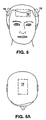
- FIG. 5 three locations for the hairbrush of Fig. 3 are shown.
- the hairbrush placed on the left side may be used to produce reference data for the hairbrush placed on the right side of the head and vice versa.
- the hairbrush may simply be moved over the object of interest to observe differences that may have been caused by abnormalities, e.g., to monitor recurrence of hematoma.
- the helmet has cutouts that are shaped as shown in 6B to receive the hairbrush 30, the cutout 44 being bounded by rigid sides 45 that serve as guides to precisely locate the hairbrush and guide it into engagement with the head, with the probes penetrating the free hair 42.
- Figure 6A shows guiding the hairbrush into the precisely known position on the sides and the top of the head.
- Figure 6 pictures diagrametrically a helmet or supporting structure with a chin strap that ensures the same position of the helmet from use to use.
- a disposable, inflatable innerliner that adapts the helmet to different sizes and shapes of heads and locates the head in the helmet in a predetermined way.
- Such liners may be disposable after each use.
- Freely extending fiber end portions 57 extend freely from the lower surface of the hairbrush, to penetrate the hair with the advantages that have been described.
- the fibers are shown to extend through the hairbrush at the top but in practice the fibers are gathered and taken by cable to the respective device such as the hematoma monitor, tumor detector or imager as described above. While the fibers are shown to be distributed uniformly, as would be the case with the imaging hairbrush shown in Figures 4 and 4A, they can be grouped in accordance with Figure 3 or put in other arrangements as may be desired.
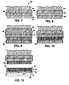
- Figures 7 through 11 The purpose of Figures 7 through 11 is to illustrate in a general way the concept that protective covers may be applied to fibers and then removed and replaced from patient to patient. Likewise the hairbrush itself may be constructed to be sterilized as in a gas autoclave.
- the ends of the fiber portions 57 extend below the hairbrush for a length suitable to penetrate the hair and reach the scalp.
- the length of the free end portions of the fibers is selected to perform that function.
- Figure 8 is a first step in the sequence to apply protectors to the ends of the fibers.
- the lower portion 64 of the hairbrush handle is lowered to the ends of the fibers, sliding on guides 66 permanently mounted on the upper portion 62 of the hairbrush.
- a sleeve dispenser also pictured at the lower part of Figure 11, is then brought into registry with suitable guides on the hairbrush such that its dispensing surface is aligned with the lower surface of the hairbrush and protector-carrying cavities within the dispenser are precisely aligned with the fibers. This is made possible by guides 67 on the dispenser that engage appropriate grooves on the brush.
- the dispenser 65 is comprised of a main body which, in the magnified views of Figures 9A through 11A, is seen to define cavities 59' in which protective sleeves 59 are placed. As shown in Figure 9, the dispensing face of the dispenser is brought face to face with the lower surface of the handle portion 64.
- the fibers 57 align precisely with the hollow spaces of the sleeves 59, the fiber ends 57 being shown flush with the lower part of handle 64 in Figure 9A.
- the length of the sleeves is for instance of the order of five times the diameter of the fibers.
- the particular length depends upon how much length of the fibers is desired to be covered, which also may depend e.g., upon other means of cleaning or sterilization to be employed.
- the end sleeves extend the full length of the fibers and are integral with cover portions that cover the bottom of the hairbrush.
- the dispenser is effective in that case to apply the entire cover to the hairbrush.
- the dispenser in the position shown, the dispenser is engaged with the hairbrush while the hairbrush lower part is spaced away the from upper part.
- the position is determined by a stop provided by slide 66 protruding from the top portion of the hairbrush, that limits the travel of the lower portion to achieve a flush or slightly withdrawn condition.
- the upper portion of handle 62 is moved downwardly to engage the lower portion of the handle to the position shown in Figure 11. Since the upper portion of the handle is fixed to the fibers, the fibers are thus carried forward, sliding in the lower portion of the handle, and the free ends of the fibers emerge from the lower part of the handle and enter the sleeves in the dispenser as depicted in Figure 10.
- tubular guides are employed between the upper and lower handle portions, one for each fiber, to prevent columnar collapse of the fibers and to ensure the sliding action just described.
- the lower portion of the dispenser comprises an activating bar 63 that is connected to a set of ejector pins, one associated with each of the sleeves within the dispenser.
- Compression springs 69 maintain the ejector bar in its lower position as shown in Figures 9 and 10.
- the ejector pins engage the ends of the fibers and their sleeves and effectively push the protected end portions out of the dispenser to the position shown in Figure 9.
- the ejector bar 63 collapsed against the lower portion of the dispenser, as shown in Figure 11 is released with the springs 69 returning to the dotted line position shown in Figure 11.
- the hairbrush as shown in Figure 9 has freely extending fiber end portions housed in protective sleeves 59 and arranged to enter the head of hair or otherwise serve the functions that have been described.
- the sleeves are translucent teflon suitable to match with the substance of the skin to transfer light from source fibers to the head and detector fibers to transfer the light to the detector.
- FIGs 12, 13, and 14 illustrate alternate preferred forms of protective sleeves for the optical fibers.
- a socket S is provided in the substance of the protective cover 59a into which a suitably shaped contrast element can be inserted.
- a contrast element vial V contains aqueous copper sulfate solution 112, which is a suitable contrast agent for MRI.
- the vial is of flexible material and can be deformed and inserted into the socket S shown in Figure 12.
- sponge rubber ball R" is shown, suitable as a contrast agent for acoustic imaging.
- An insert of solid sodium iodide crystals is appropriate for xray.
- Different protective sleeves can be provided having different contrast agents, to enable dual mode examination, for instance with MRI or acoustic imaging. Other contrast agents for other modes of examination can be used.
- annular end portion E of the sleeve which protrudes below the crossing plate that closes the bottom of the protective cavity formed by sleeve 59a.
- the optical fiber 57 is intended to extend the full length of that cavity and engage the bottom of the cavity, to be immersed in an optional optical matching fluid having the same refractive index as the fiber and the sleeve, to avoid a change of refractive index that can occasion light loss.
- the annular end portion E serves as a light dam or barrier.
- an outer black coating or other means of achieving opacity is provided about the end tips.
- the substance of the tubular sleeve 59b is an opaque elastomer.
- the ends E' serve the function of the ends E in Figure 12 and the cross member shown but not labeled in Figure 13 serves to form the bottom cap and protect the fiber from contaminating conditions.
- the outer wall of the sleeve 59b is provided with a recess R' into which a contrast ring shown in Figure 13A can be inserted.
- Figure 13B illustrates a cross section of such a contrast ring, element R, of sponge rubber to serve as a contrast agent for acoustic imaging.
- the ring is hollow and has copper sulfate in aqueous solution contained by fluid impermeable walls 110 of the ring.
- the ring can contain sodium iodide crystals.
- a lens L is employed for the advantage of collecting additional light for transmission up the fiber.
- the terminal end of the fiber is enlarged to provide sufficient area contact to provide comfort to the patient.
- the form is particularly useful with small or stiff fibers which have a tendency to produce pain.
- the fibers instead of a separable element, the fibers themselves are configured to have enlarged end portions, for instance balls formed by melting the ends for achieving comfort. In such cases, the fibers are advantageously provided with an outer coating e.g. titanium dioxide paint or other pigment to achieve a diffusing condition to facilitate the transfer of light.
- a breast examination system employing brushes 150, 160 and 150' and 160'.
- the brushes are defined by a comfortable mass of free ended fibers that conform to the breast and transmit light in a desirable way. As shown the fibers extend across the entire base of the brush, however fibers arranged as in Figures 3 and 3a may also be employed.
- the signals from the relative symmetrical left and right inner breast surfaces are taken to bilateral comparator 162 whereas the similar signals from the outer surfaces of the left and right breasts, from detectors 150, 150', are taken to bilateral comparator 152.
- the results of the two comparisons may be also correlated to further elaborate the examination.
- a comfortable brassier like breast examination device is shown.
- the brassier-like device is applied in the same way each time and enables the position from measurement to measurement to be accurately known so that comparison to a base-line condition can be made. Even without such reference, the examination is useful to determine presence of an inhomogene to identify a condition that requires further diagnosis.
- contrast agent is not suggested for use in this examination of breast tissue. In the event monitoring suggests a problem, a contrast agent may be administered to more effectively examine the tissue spectrophotometrically, or examination by another modality, though much more costly, may then be indicated.
- thermoplastic that softens at comfortable temperature, about the object to be examined, and when cooling, to use that form either directly as a guide to bring a hairbrush or other monitoring device into position for repetitive readings.
Landscapes
- Health & Medical Sciences (AREA)
- Life Sciences & Earth Sciences (AREA)
- Physics & Mathematics (AREA)
- Surgery (AREA)
- General Health & Medical Sciences (AREA)
- Biophysics (AREA)
- Pathology (AREA)
- Engineering & Computer Science (AREA)
- Biomedical Technology (AREA)
- Heart & Thoracic Surgery (AREA)
- Medical Informatics (AREA)
- Molecular Biology (AREA)
- Veterinary Medicine (AREA)
- Animal Behavior & Ethology (AREA)
- Public Health (AREA)
- Optics & Photonics (AREA)
- Spectroscopy & Molecular Physics (AREA)
- Neurology (AREA)
- Nuclear Medicine, Radiotherapy & Molecular Imaging (AREA)
- Radiology & Medical Imaging (AREA)
- Gynecology & Obstetrics (AREA)
- Reproductive Health (AREA)
- Measurement Of The Respiration, Hearing Ability, Form, And Blood Characteristics Of Living Organisms (AREA)
- Investigating Or Analysing Materials By Optical Means (AREA)
- Investigating, Analyzing Materials By Fluorescence Or Luminescence (AREA)
Claims (26)
- Eine optische Eingangs- und Ausgangskopplervorrichtung (30, 150, 160, 170) zur Verwendung mit einer optischen Untersuchungsvorrichtung für in vivo Untersuchung biologischen Gewebes wobei die optische Kopplervorrichtung konstruiert ist, um Photonen zwischen einer optischen Quelle oder einem Detektor und biologischem Gewebe des Gehirns oder eines anderen geeigneten Körperteils, der untersucht wird, zu übertragen, wobei die optische Kopplervorrichtung eine Anordnung von Glasfasern bzw. Lichtleitfasern (36, 36a, 36b) ist, wobei Endteilen davon frei als freitragende Arme von einer Halterung (34) in der Art und Weise von Borsten einer Haarbürste herausragen, wobei die Endteile der Fasern bemessen und verteilt sind, um sich frei erstreckendes Haar (42) auf dem Kopf oder einer anderen Oberfläche einer Versuchperson zu durchdringen, um optischen Kontakt direkt über eine Anordnung von Punkten mit der Oberfläche der Kopfhaut oder Haut unterhalb der freien Haare herzustellen, wobei ein Satz von Fasern (36a) in der Lage ist, Licht zu dem untersuchten biologischen Gewebe von der optischen Quelle zu übertragen und wobei der Satz von Fasern (36b) in der Lage ist, Licht aufzunehmen, das in das untersuchte biologische Gewebe migriert ist.
- Die optische Kopplervorrichtung gemäß Anspruch 1, wobei die vorragenden Endteile der Fasern derart bemessen sind, um eine Länge und einen Durchmesser zu besitzen, um ausgewählte säulenartige Eigenschaften zum Liefern des Kontakts zu besitzen.
- Die optische Kopplervorrichtung gemäß Anspruch 1 oder 2, wobei die Glasfasern bzw. Lichtleitfasern seitlich elastisch flexibel_sind, so dass sie sich biegen und sich die Muster der Faserspitzen den Variationen in der Form des Schädels, der Brust oder anderer Körperteile anpassen.
- Die optische Kopplervorrichtung gemäß Anspruch 1 oder 2, wobei die Lichtleitfasern proximale Enden aufweisen, die proximal zu den Kontakt liefernden Endteilen gelegen sind, wobei die proximalen Enden optisch an einen Faserselektor bzw. Faserwähler (92) gekoppelt sind, um optische Kopplung an die optische Quelle oder den optischen Detektor zu liefern.
- Die optische Kopplervorrichtung gemäß Anspruch 4, wobei mit der optischen Quelle Quellenfasern (36a) verbunden sind.
- Die optische Kopplervorrichtung gemäß Anspruch 4, wobei mit dem optischen Detektor Detektorfasern (36b) verbunden sind.
- Die optische Kopplervorrichtung gemäß Anspruch 5 oder 6, wobei die Quellenfasern oder die Detektorfasern durch Verwenden des Faserwählers auswählbar sind.
- Die optische Kopplervorrichtung gemäß einem der vorhergehenden Ansprüche, wobei der Vorrichtung Mittel zum Leiten des Lichts in die Faser zugeordnet sind.
- Die optische Kopplervorrichtung gemäß einem der vorhergehenden Ansprüche, wobei die sich frei erstreckenden Endteile der Fasern ein Längen-zu-Durchmesser-Verhältnis von zwischen 5 und 200 besitzen.
- Die optische Kopplervorrichtung gemäß Anspruch 9, wobei das Verhältnis zwischen ungefähr 20 und 150 liegt.
- Die optische Kopplervorrichtung gemäß Anspruch 10, wobei das Verhältnis zwischen ungefähr 50 und 125 liegt.
- Die optische Kopplervorrichtung gemäß einem der vorhergehenden Ansprüche, wobei die freien Endteile der Lichtleitfasern einen Durchmesser in der Größenordnung von 0,1 Millimeter bis 3,0 Millimeter und eine Länge zwischen ungefähr 0,5 cm bis 3 cm besitzen.
- Die optische Kopplervorrichtung gemäß Anspruch 12, in wobei die freien Endteile der Lichtleitfasern einen Durchmesser von ungefähr 0,2 bis 0,5 Millimeter und eine Länge zwischen ungefähr 1 und 2,5 cm besitzen.
- Die optische Kopplervorrichtung gemäß einem der vorhergehenden Ansprüche, wobei die Lichtleitfasern Einzelmodusfasern sind.
- Die optische Kopplervorrichtung gemäß einem der vorhergehenden Ansprüche, wobei die Lichtleitfasern glatte, vergrößerte Spitzen besitzen, die komfortabel in Eingriff mit der Haut oder Kopfhaut stehen.
- Die optische Kopplervorrichtung gemäß einem der Ansprüche 1 bis 5, die angeordnet und verbunden ist, um das Gehirn abzubilden.
- Die optische Kopplervorrichtung gemäß einem der Ansprüche 1 bis 5, die angeordnet und verbunden ist, um die Brust abzubilden.
- Die optische Kopplervorrichtung gemäß einem der vorhergehenden Ansprüche, die eine Endhülse aufweist, die sich über das Ende des sich frei erstreckenden Faserteils erstreckt und angeordnet ist, um in Eingriff mit dem Gewebe zu stehen, um die Lichtübertragung entlang der Oberfläche des in Eingriff stehenden Gewebes zu verhindern.
- Die optische Kopplervorrichtung gemäß Anspruch 18, wobei die Endhülse flexibel ist und konstruiert wurde, um sich dem Gewebe anzupassen.
- Die optische Kopplervorrichtung gemäß Anspruch 18 oder 19, wobei Umfangsteile der Endhülse einen Lichtabsorber beinhalten.
- Die optische Kopplervorrichtung gemäß einem der vorhergehenden Ansprüche zur Verwendung mit einem Kunststoffreferenzglied (40), das gemäß der Kontur der Versuchsperson geformt bzw. gegossen ist.
- Die optische Kopplervorrichtung gemäß Anspruch 7, wobei der Faserwähler optisch mit einem Spektrophotometer gekoppelt ist, um Veränderungen im Gehirn zu überwachen.
- Die optische Kopplervorrichtung gemäß Anspruch 7, wobei der Faserwähler optisch mit einem Spektrophotometer gekoppelt ist, um Gehirnblutung zu überwachen.
- Die optische Kopplervorrichtung gemäß einem der vorhergehenden Ansprüche, die ferner ein Einwegschutzelement aufweist, das zumindest einige der Endteile für den Eingriff mit der Versuchsperson umgibt.
- Die optische Kopplervorrichtung gemäß Anspruch 24, wobei das Einwegschutzelement einen Endbecher oder eine Hülse aufweist.
- Die optische Kopplervorrichtung gemäß Anspruch 25, in der ein Endbereich des Bechers oder der Hülse ein Kontrastmedium trägt.
Applications Claiming Priority (8)
| Application Number | Priority Date | Filing Date | Title |
|---|---|---|---|
| US08/367,939 US5596987A (en) | 1988-11-02 | 1995-01-03 | Optical coupler for in vivo examination of biological tissue |
| PCT/US1995/015694 WO1996016596A1 (en) | 1994-12-02 | 1995-12-04 | Optical techniques for examination of biological tissue |
| WOPCT/US95/15694 | 1995-12-04 | ||
| PCT/US1995/015666 WO1996016592A1 (en) | 1994-12-02 | 1995-12-04 | Monitoring one or more solutes in a biological system using optical techniques |
| WOPCT/US95/15666 | 1995-12-04 | ||
| WOPCT/US96/00235 | 1996-01-02 | ||
| PCT/US1996/000235 WO1996020638A1 (en) | 1995-01-03 | 1996-01-02 | Optical coupler for in vivo examination of biological tissue |
| PCT/US1996/011630 WO1997020494A1 (en) | 1995-01-03 | 1996-07-12 | Optical examination device, system and method |
Publications (3)
| Publication Number | Publication Date |
|---|---|
| EP0906052A1 EP0906052A1 (de) | 1999-04-07 |
| EP0906052A4 EP0906052A4 (de) | 1999-04-07 |
| EP0906052B1 true EP0906052B1 (de) | 2006-05-10 |
Family
ID=23449241
Family Applications (2)
| Application Number | Title | Priority Date | Filing Date |
|---|---|---|---|
| EP96902117A Expired - Lifetime EP0808124B1 (de) | 1995-01-03 | 1996-01-02 | Optische koppelvorrichtung zur in-vivo untersuchung von biologischen geweben |
| EP96921808A Expired - Lifetime EP0906052B1 (de) | 1995-01-03 | 1996-07-12 | Optischer koppler für eine optische untersuchungsvorrichtung |
Family Applications Before (1)
| Application Number | Title | Priority Date | Filing Date |
|---|---|---|---|
| EP96902117A Expired - Lifetime EP0808124B1 (de) | 1995-01-03 | 1996-01-02 | Optische koppelvorrichtung zur in-vivo untersuchung von biologischen geweben |
Country Status (7)
| Country | Link |
|---|---|
| US (5) | US5987351A (de) |
| EP (2) | EP0808124B1 (de) |
| JP (1) | JP3725156B2 (de) |
| CN (1) | CN1230118C (de) |
| CA (1) | CA2209240C (de) |
| DE (1) | DE69627477T2 (de) |
| WO (2) | WO1996020638A1 (de) |
Families Citing this family (186)
| Publication number | Priority date | Publication date | Assignee | Title |
|---|---|---|---|---|
| US5353799A (en) | 1991-01-22 | 1994-10-11 | Non Invasive Technology, Inc. | Examination of subjects using photon migration with high directionality techniques |
| US6397099B1 (en) | 1992-05-18 | 2002-05-28 | Non-Invasive Technology, Inc. | Non-invasive imaging of biological tissue |
| US5853370A (en) | 1996-09-13 | 1998-12-29 | Non-Invasive Technology, Inc. | Optical system and method for non-invasive imaging of biological tissue |
| US5987346A (en) * | 1993-02-26 | 1999-11-16 | Benaron; David A. | Device and method for classification of tissue |
| US5803909A (en) * | 1994-10-06 | 1998-09-08 | Hitachi, Ltd. | Optical system for measuring metabolism in a body and imaging method |
| US20050043596A1 (en) * | 1996-07-12 | 2005-02-24 | Non-Invasive Technology, Inc., A Delaware Corporation | Optical examination device, system and method |
| JP3725156B2 (ja) * | 1995-01-03 | 2005-12-07 | ノン−インヴェイシヴ テクノロジイ,インク. | 生物組織の生体内検査用の光学カプラ |
| US6618614B1 (en) | 1995-01-03 | 2003-09-09 | Non-Invasive Technology, Inc. | Optical examination device, system and method |
| US6152876A (en) * | 1997-04-18 | 2000-11-28 | Rio Grande Medical Technologies, Inc. | Method for non-invasive blood analyte measurement with improved optical interface |
| US6240309B1 (en) * | 1995-10-06 | 2001-05-29 | Hitachi, Ltd. | Optical measurement instrument for living body |
| US20060184047A1 (en) * | 1995-11-17 | 2006-08-17 | Yuichi Yamashita | Optical measurement instrument for living body |
| WO1998044839A1 (en) * | 1997-04-03 | 1998-10-15 | National Research Council Of Canada | Method of assessing tissue viability using near-infrared spectroscopy |
| DE69825244T2 (de) | 1997-05-09 | 2005-07-21 | Koninklijke Philips Electronics N.V. | Vorrichtung zur auffindung eines körpers in einem trüben medium |
| US6675035B1 (en) * | 1997-06-20 | 2004-01-06 | Imaging Diagnostic Systems, Inc. | Phantom for optical and magnetic resonance imaging quality control |
| DE69934482T2 (de) | 1998-02-11 | 2007-09-27 | Non-Invasive Technology, Inc. | Nachweis, abbildung und kennzeichnung von brustumoren |
| WO1999040841A1 (en) | 1998-02-11 | 1999-08-19 | Non-Invasive Technology, Inc. | Imaging and characterization of brain tissue |
| WO1999040842A1 (en) | 1998-02-13 | 1999-08-19 | Non-Invasive Technology, Inc. | Transabdominal examination, monitoring and imaging of tissue |
| JP4006826B2 (ja) | 1998-04-28 | 2007-11-14 | 株式会社日立製作所 | 生体光計測装置 |
| US6592847B1 (en) * | 1998-05-14 | 2003-07-15 | The General Hospital Corporation | Intramolecularly-quenched near infrared flourescent probes |
| WO1999065387A1 (en) * | 1998-06-19 | 1999-12-23 | Uab Research Foundation | Oximetric tonometer with intracranial pressure monitoring capability |
| CA2337871A1 (en) * | 1998-07-30 | 2000-02-10 | Yissum Research Development Company Of The Hebrew University Of Jerusalem | Optical mammography |
| US6949081B1 (en) | 1998-08-26 | 2005-09-27 | Non-Invasive Technology, Inc. | Sensing and interactive drug delivery |
| US6741884B1 (en) | 1998-09-03 | 2004-05-25 | Hypermed, Inc. | Infrared endoscopic balloon probes |
| US8024027B2 (en) | 1998-09-03 | 2011-09-20 | Hyperspectral Imaging, Inc. | Infrared endoscopic balloon probes |
| AU5908699A (en) * | 1998-09-03 | 2000-03-27 | Hypermed Imaging, Inc. | Infrared endoscopic balloon probes |
| USRE45607E1 (en) * | 1998-10-13 | 2015-07-14 | Covidien Lp | Multi-channel non-invasive tissue oximeter |
| EP1008925B1 (de) | 1998-12-07 | 2006-01-11 | Hitachi, Ltd. | Vorrichtung zur Steuerung von Anlagen mit Hilfe von Körpersignalen |
| US7047054B2 (en) * | 1999-03-12 | 2006-05-16 | Cas Medical Systems, Inc. | Laser diode optical transducer assembly for non-invasive spectrophotometric blood oxygenation monitoring |
| JP4482238B2 (ja) | 1999-03-23 | 2010-06-16 | コーニンクレッカ フィリップス エレクトロニクス エヌ ヴィ | 濁り媒体中の対象物の場所を限定する装置 |
| JP4484373B2 (ja) * | 1999-03-29 | 2010-06-16 | 株式会社日立メディコ | 生体光計測装置 |
| IL129398A (en) * | 1999-04-12 | 2005-05-17 | Israel Atomic Energy Comm | Metabolism monitoring or body organs |
| US6167297A (en) * | 1999-05-05 | 2000-12-26 | Benaron; David A. | Detecting, localizing, and targeting internal sites in vivo using optical contrast agents |
| DE69943188D1 (de) * | 1999-06-03 | 2011-03-24 | Hamamatsu Photonics Kk | Optische ct-vorrichtung und verfahren zur wiederherstellung von bildern |
| US7840257B2 (en) | 2003-01-04 | 2010-11-23 | Non Invasive Technology, Inc. | Examination of biological tissue using non-contact optical probes |
| US7904139B2 (en) | 1999-08-26 | 2011-03-08 | Non-Invasive Technology Inc. | Optical examination of biological tissue using non-contact irradiation and detection |
| DE60031551T2 (de) * | 1999-08-31 | 2007-08-23 | Nir Diagnostics Inc., Waterloo | Vorrichtung zur überprüfung der genauigkeit eines spektralanalysators |
| AU7579300A (en) * | 1999-09-14 | 2001-04-17 | Research Foundation of State University of New York, Technology Transfer Office, The | Method and system for imaging the dynamics of scattering medium |
| US7280866B1 (en) | 1999-10-06 | 2007-10-09 | National Research Council Of Canada | Non-invasive screening of skin diseases by visible/near-infrared spectroscopy |
| DE19954756A1 (de) * | 1999-11-17 | 2001-05-31 | Odim Gmbh | Gerät und Verfahren zur Untersuchung von biologischem Gewebe |
| US7006676B1 (en) | 2000-01-21 | 2006-02-28 | Medical Optical Imaging, Inc. | Method and apparatus for detecting an abnormality within a host medium utilizing frequency-swept modulation diffusion tomography |
| WO2001054580A1 (en) | 2000-01-27 | 2001-08-02 | National Research Council Of Canada | Visible-near infrared spectroscopy in burn injury assessment |
| DE10004989B4 (de) * | 2000-02-04 | 2006-11-02 | Siemens Ag | Verfahren und Vorrichtung für die Arthritis-Diagnose |
| US6587703B2 (en) | 2000-09-18 | 2003-07-01 | Photonify Technologies, Inc. | System and method for measuring absolute oxygen saturation |
| US6516209B2 (en) | 2000-08-04 | 2003-02-04 | Photonify Technologies, Inc. | Self-calibrating optical imaging system |
| US6801648B2 (en) | 2000-08-04 | 2004-10-05 | Xuefeng Cheng | Optical imaging system with symmetric optical probe |
| US6597931B1 (en) | 2000-09-18 | 2003-07-22 | Photonify Technologies, Inc. | System and method for absolute oxygen saturation |
| US6719686B2 (en) * | 2000-08-30 | 2004-04-13 | Mallinckrodt, Inc. | Fetal probe having an optical imaging device |
| US7383076B2 (en) * | 2000-11-27 | 2008-06-03 | The General Hospital Corporation | Fluorescence-mediated molecular tomography |
| US6826424B1 (en) * | 2000-12-19 | 2004-11-30 | Haishan Zeng | Methods and apparatus for fluorescence and reflectance imaging and spectroscopy and for contemporaneous measurements of electromagnetic radiation with multiple measuring devices |
| US20030044353A1 (en) * | 2001-01-05 | 2003-03-06 | Ralph Weissleder | Activatable imaging probes |
| DE10109539A1 (de) * | 2001-02-28 | 2002-09-12 | Siemens Ag | Vorrichtung zur Untersuchung von Gewebe mit Licht |
| WO2002097404A1 (en) * | 2001-05-30 | 2002-12-05 | Sciperio, Inc. | System, method, and apparatus for non-intrusively determining concentration of a solute in a solution |
| US6659941B2 (en) * | 2001-06-19 | 2003-12-09 | Mallinckrodt, Inc. | Balloon assisted endoscope for viewing a fetus during delivery |
| US7047057B2 (en) * | 2001-07-16 | 2006-05-16 | Art. Advanced Research Technologies Inc. | Simultaneous multiwavelength TPSF-based optical imaging |
| US20030062485A1 (en) * | 2001-09-28 | 2003-04-03 | Fernandez Salvador M. | Compact multiwavelength phase fluorometer |
| US20050107709A1 (en) * | 2002-04-02 | 2005-05-19 | Technische Universitat Dresden | Method and arrangement for optically measuring swelling of the nose |
| EP1514093B1 (de) | 2002-06-04 | 2021-04-28 | Visen Medical, Inc. | Abbildung von volumen mit beliebigen geometrien in nichtberührenden tomographie |
| JP4465271B2 (ja) | 2002-07-26 | 2010-05-19 | シーエーエス・メディカル・システムズ・インコーポレイテッド | 対象組織内の血液酸素飽和度を非侵襲的に決定する装置 |
| US7087075B2 (en) | 2002-09-30 | 2006-08-08 | Medtronic Emergency Response Systems, Inc. | Feedback system for rapid induction of mild hypothermia |
| US7179279B2 (en) | 2002-09-30 | 2007-02-20 | Medtronic Physio Control Corp. | Rapid induction of mild hypothermia |
| DE60334007D1 (de) | 2002-10-01 | 2010-10-14 | Nellcor Puritan Bennett Inc | Verwendung eines Kopfbandes zur Spannungsanzeige und System aus Oxymeter und Kopfband |
| US7698909B2 (en) | 2002-10-01 | 2010-04-20 | Nellcor Puritan Bennett Llc | Headband with tension indicator |
| US7056282B2 (en) | 2002-12-23 | 2006-06-06 | Medtronic Emergency Response Systems, Inc. | Coolant control for rapid induction of mild hypothermia |
| AU2003203069A1 (en) * | 2003-01-22 | 2004-08-13 | Art, Advanced Research Technologies, Inc. | Simultaneous acquisition of different time-gates in tpsf-based optical imaging |
| US7647091B2 (en) * | 2003-02-05 | 2010-01-12 | The General Hospital Corporation | Method and system for free space optical tomography of diffuse media |
| CN100557420C (zh) * | 2003-02-06 | 2009-11-04 | 皇家飞利浦电子股份有限公司 | 用于血液分析的装置和方法 |
| US7047056B2 (en) * | 2003-06-25 | 2006-05-16 | Nellcor Puritan Bennett Incorporated | Hat-based oximeter sensor |
| US6949072B2 (en) * | 2003-09-22 | 2005-09-27 | Infraredx, Inc. | Devices for vulnerable plaque detection |
| US8412297B2 (en) | 2003-10-01 | 2013-04-02 | Covidien Lp | Forehead sensor placement |
| KR100561857B1 (ko) * | 2004-01-12 | 2006-03-16 | 삼성전자주식회사 | 경혈점 검출 장치 및 방법 |
| US7491169B2 (en) | 2004-03-22 | 2009-02-17 | The United States Of America As Represented By The Administrator Of The National Aeronautics And Space Administration | Ultrasonic apparatus and method to assess compartment syndrome |
| US8060172B2 (en) * | 2004-03-29 | 2011-11-15 | Olympus Corporation | In-vivo information measurement apparatus |
| US7570979B2 (en) * | 2004-03-30 | 2009-08-04 | Philip George Cooper | Methods and apparatus for patient monitoring |
| US7313425B2 (en) * | 2004-07-08 | 2007-12-25 | Orsense Ltd. | Device and method for non-invasive optical measurements |
| US7381186B2 (en) * | 2004-08-02 | 2008-06-03 | The United States Of America As Represented By The Administrator Of The National Aeronautics And Space Administration | Method and apparatus to assess compartment syndrome |
| US20060094940A1 (en) * | 2004-09-21 | 2006-05-04 | Art, Advanced Research Technologies, Inc. | Method for selecting wavelengths for optical data acquisition |
| US8062224B2 (en) * | 2004-10-28 | 2011-11-22 | Uab Vittamed | Method and apparatus for non-invasive continuous monitoring of cerebrovascular autoregulation state |
| US7298009B2 (en) * | 2005-02-01 | 2007-11-20 | Infineon Technologies Ag | Semiconductor method and device with mixed orientation substrate |
| US8060189B2 (en) | 2005-05-06 | 2011-11-15 | Infrascan, Inc. | System and method for detection of hematoma |
| WO2006124696A1 (en) * | 2005-05-13 | 2006-11-23 | Children's Hospital Medical Center | Multi-wavelength spatial domain near infrared oximeter to detect cerebral hypoxia-ischemia |
| US7736382B2 (en) | 2005-09-09 | 2010-06-15 | Lockheed Martin Corporation | Apparatus for optical stimulation of nerves and other animal tissue |
| US20070093708A1 (en) * | 2005-10-20 | 2007-04-26 | Benaron David A | Ultra-high-specificity device and methods for the screening of in-vivo tumors |
| US8956396B1 (en) | 2005-10-24 | 2015-02-17 | Lockheed Martin Corporation | Eye-tracking visual prosthetic and method |
| US8475506B1 (en) | 2007-08-13 | 2013-07-02 | Lockheed Martin Corporation | VCSEL array stimulator apparatus and method for light stimulation of bodily tissues |
| US8012189B1 (en) | 2007-01-11 | 2011-09-06 | Lockheed Martin Corporation | Method and vestibular implant using optical stimulation of nerves |
| US7802690B2 (en) * | 2005-10-24 | 2010-09-28 | Portola Packaging, Inc. | Closure having expanded peripheral surface |
| US8945197B1 (en) | 2005-10-24 | 2015-02-03 | Lockheed Martin Corporation | Sight-restoring visual prosthetic and method using infrared nerve-stimulation light |
| US8709078B1 (en) | 2011-08-03 | 2014-04-29 | Lockheed Martin Corporation | Ocular implant with substantially constant retinal spacing for transmission of nerve-stimulation light |
| US8792978B2 (en) | 2010-05-28 | 2014-07-29 | Lockheed Martin Corporation | Laser-based nerve stimulators for, E.G., hearing restoration in cochlear prostheses and method |
| US20080077200A1 (en) * | 2006-09-21 | 2008-03-27 | Aculight Corporation | Apparatus and method for stimulation of nerves and automated control of surgical instruments |
| CN101312682B (zh) * | 2005-11-23 | 2011-05-25 | 皇家飞利浦电子股份有限公司 | 用于对混浊介质进行光学成像的方法和装置 |
| US7559945B2 (en) | 2006-01-13 | 2009-07-14 | Clarimedix Inc. | Multi-spectral photon therapy device and methods of use |
| WO2007087560A2 (en) * | 2006-01-26 | 2007-08-02 | The Board Of Trustees Of The University Of Illinois | Stroke inducing and monitoring system and method for using the same |
| WO2007109124A2 (en) * | 2006-03-16 | 2007-09-27 | The Trustees Of Boston University | Electro-optical sensor for peripheral nerves |
| US20070282404A1 (en) * | 2006-04-10 | 2007-12-06 | University Of Rochester | Side-firing linear optic array for interstitial optical therapy and monitoring using compact helical geometry |
| CN101511263B (zh) * | 2006-09-07 | 2011-11-23 | 皇家飞利浦电子股份有限公司 | 使用容纳体积的合适边沿的光学层析x射线照相术测量 |
| US8996131B1 (en) | 2006-09-28 | 2015-03-31 | Lockheed Martin Corporation | Apparatus and method for managing chronic pain with infrared light sources and heat |
| US8498699B2 (en) | 2008-10-03 | 2013-07-30 | Lockheed Martin Company | Method and nerve stimulator using simultaneous electrical and optical signals |
| US8116852B2 (en) | 2006-09-29 | 2012-02-14 | Nellcor Puritan Bennett Llc | System and method for detection of skin wounds and compartment syndromes |
| EP2088921A1 (de) * | 2006-10-30 | 2009-08-19 | Koninklijke Philips Electronics N.V. | Abbildung eines trüben mediums |
| CN101534703A (zh) * | 2006-11-17 | 2009-09-16 | 皇家飞利浦电子股份有限公司 | 用于对混浊介质的内部进行成像的设备 |
| US7936459B1 (en) * | 2006-11-21 | 2011-05-03 | David Coombs | Apparatus with probe |
| US7983740B2 (en) * | 2006-12-22 | 2011-07-19 | Washington University | High performance imaging system for diffuse optical tomography and associated method of use |
| US7883536B1 (en) | 2007-01-19 | 2011-02-08 | Lockheed Martin Corporation | Hybrid optical-electrical probes |
| US8100834B2 (en) | 2007-02-27 | 2012-01-24 | J&M Shuler, Inc. | Method and system for monitoring oxygenation levels of a compartment for detecting conditions of a compartment syndrome |
| US8639309B2 (en) | 2007-07-31 | 2014-01-28 | J&M Shuler, Inc. | Method and system for monitoring oxygenation levels of compartments and tissue |
| US20080228053A1 (en) * | 2007-03-15 | 2008-09-18 | Shih-Ping Wang | Method and system for cerebral oxygenation level monitoring |
| US9226731B2 (en) * | 2007-05-21 | 2016-01-05 | The Board Of Regents Of The University Of Texas System | Optically guided needle biopsy system using multi-modal spectroscopy in combination with a transrectal ultrasound probe |
| ATE548637T1 (de) * | 2007-09-24 | 2012-03-15 | Univ Potsdam | Messanordnung für ein optisches spektrometer |
| WO2009050633A1 (en) * | 2007-10-19 | 2009-04-23 | Koninklijke Philips Electronics N.V. | Device for imaging the interior of an optically turbid medium and receptacle unit for such a device |
| JP5420163B2 (ja) * | 2007-10-24 | 2014-02-19 | 浜松ホトニクス株式会社 | 生体計測装置 |
| US9011508B2 (en) | 2007-11-30 | 2015-04-21 | Lockheed Martin Corporation | Broad wavelength profile to homogenize the absorption profile in optical stimulation of nerves |
| US8380272B2 (en) * | 2007-12-21 | 2013-02-19 | Covidien Lp | Physiological sensor |
| US8815214B2 (en) * | 2008-01-18 | 2014-08-26 | Visen Medical, Inc. | Fluorescent imaging agents |
| DE102008011013B4 (de) * | 2008-02-25 | 2014-11-13 | Mevitec Gmbh | Verfahren und Einrichtung zur komplexen Stoffwechselanalyse |
| US8243071B2 (en) * | 2008-02-29 | 2012-08-14 | Microsoft Corporation | Modeling and rendering of heterogeneous translucent materials using the diffusion equation |
| US20090234245A1 (en) * | 2008-03-17 | 2009-09-17 | O2 Medtech, Inc. | Non-invasive monitoring of intracranial pressure |
| US9480425B2 (en) * | 2008-04-17 | 2016-11-01 | Washington University | Task-less optical mapping of dynamic brain function using resting state functional connectivity |
| CA3162577C (en) | 2008-05-20 | 2023-09-26 | University Health Network | Device and method for fluorescence-based imaging and monitoring |
| US20100004518A1 (en) | 2008-07-03 | 2010-01-07 | Masimo Laboratories, Inc. | Heat sink for noninvasive medical sensor |
| US20100016731A1 (en) * | 2008-07-15 | 2010-01-21 | Cardiox Corporation | Hemodynamic Detection of Circulatory Anomalies |
| US8353833B2 (en) | 2008-07-18 | 2013-01-15 | University Of Rochester | Low-cost device for C-scan photoacoustic imaging |
| DE102008050109B4 (de) * | 2008-07-21 | 2010-06-17 | Ancosys Gmbh | Optischer Sensor |
| US8630691B2 (en) * | 2008-08-04 | 2014-01-14 | Cercacor Laboratories, Inc. | Multi-stream sensor front ends for noninvasive measurement of blood constituents |
| JP5771525B2 (ja) * | 2008-09-18 | 2015-09-02 | セダーズ−シナイ メディカル センター | アルツハイマー病を検出するための光学的方法 |
| US8364220B2 (en) | 2008-09-25 | 2013-01-29 | Covidien Lp | Medical sensor and technique for using the same |
| US8257274B2 (en) | 2008-09-25 | 2012-09-04 | Nellcor Puritan Bennett Llc | Medical sensor and technique for using the same |
| CN102164534B (zh) * | 2008-09-26 | 2014-07-23 | 皇家飞利浦电子股份有限公司 | 具有可变容积的检测室 |
| WO2010058339A2 (en) * | 2008-11-21 | 2010-05-27 | Koninklijke Philips Electronics N.V. | Imaging a turbid medium |
| WO2010061339A1 (en) * | 2008-11-26 | 2010-06-03 | Koninklijke Philips Electronics N.V. | Device and method for optically examining the interior of a turbid medium |
| US8515515B2 (en) | 2009-03-25 | 2013-08-20 | Covidien Lp | Medical sensor with compressible light barrier and technique for using the same |
| US8781548B2 (en) | 2009-03-31 | 2014-07-15 | Covidien Lp | Medical sensor with flexible components and technique for using the same |
| US20120095305A1 (en) * | 2009-06-15 | 2012-04-19 | O2 Medtech, Inc. | Spectrophotometric Monitoring Of Multiple Layer Tissue Structures |
| WO2011006159A1 (en) * | 2009-07-10 | 2011-01-13 | Cas Medical Systems, Inc. | Method for spectrophotometric blood oxygenation monitoring of the lower gastrointesinal tract |
| US8688183B2 (en) | 2009-09-03 | 2014-04-01 | Ceracor Laboratories, Inc. | Emitter driver for noninvasive patient monitor |
| FR2950431B1 (fr) | 2009-09-24 | 2011-12-09 | Commissariat Energie Atomique | Dispositif et procede de reconstruction spatiale d'une cartographie de fluorescence |
| FR2951283B1 (fr) * | 2009-10-08 | 2013-02-15 | Commissariat Energie Atomique | Procede et dispositif pour l'excitation diffuse en imagerie |
| CN102883658B (zh) * | 2009-11-19 | 2016-06-22 | 调节成像公司 | 用于使用结构化照明经由单元件检测来分析浑浊介质的方法和设备 |
| DE102010014702A1 (de) * | 2010-04-12 | 2011-10-13 | Mbr Optikal Systems Gmbh & Co. Kg | Messanordnung zur Aufzeichnung eines Spektrums, insbesondere auf vitalem Gewebe |
| US10314650B2 (en) | 2010-06-16 | 2019-06-11 | Biosense Webster (Israel) Ltd. | Spectral sensing of ablation |
| US11490957B2 (en) | 2010-06-16 | 2022-11-08 | Biosense Webster (Israel) Ltd. | Spectral sensing of ablation |
| DE102010026068B4 (de) * | 2010-07-05 | 2017-09-28 | Emz-Hanauer Gmbh & Co. Kgaa | Optischer Sensor, insbesondere zum Einbau in eine Waschmaschine oder eine Geschirrspülmaschine der Haushaltsausstattung |
| US8648321B2 (en) | 2010-07-05 | 2014-02-11 | Emz-Hanauer Gmbh & Co. Kgaa | Optical sensor for use in a domestic washing machine or dishwasher |
| WO2012032413A2 (en) * | 2010-09-07 | 2012-03-15 | Cnsystems Medizintechnik Ag | Disposable and detachable sensor for continuous non-invasive arterial blood pressure monitoring |
| US9775545B2 (en) | 2010-09-28 | 2017-10-03 | Masimo Corporation | Magnetic electrical connector for patient monitors |
| WO2012050847A2 (en) | 2010-09-28 | 2012-04-19 | Masimo Corporation | Depth of consciousness monitor including oximeter |
| CN103282764A (zh) * | 2010-10-29 | 2013-09-04 | 尼尔科学公司 | 用于分析物检测的方法和装置 |
| WO2012061584A2 (en) | 2010-11-03 | 2012-05-10 | University Of Washington Through Its Center For Commercialization | Deternimation of tissue oxygenation in vivo |
| FR2968921B1 (fr) | 2010-12-15 | 2013-01-11 | Commissariat Energie Atomique | Procede de localisation d'un marqueur optique dans un milieu diffusant |
| CN102551736A (zh) * | 2012-01-19 | 2012-07-11 | 西北工业大学 | 一种光传感系统 |
| WO2013127819A1 (en) * | 2012-02-27 | 2013-09-06 | Apd Advanced Perfusion Diagnostics | Apparatus and method for measuring blood flow within the gastrointestinal tract |
| US10034647B2 (en) * | 2012-03-16 | 2018-07-31 | Xidian University | System and method for endoscopic X-ray luminescence computed tomographic imaging |
| EP2861132B1 (de) | 2012-06-13 | 2020-11-18 | Dean Nahman | Vorrichtung zur erkennung von inneren blutungen und blutergüssen |
| US20140046170A1 (en) * | 2012-08-07 | 2014-02-13 | Chia-Wei Sun | Brain volumetric measuring method and system using the same |
| US20140051975A1 (en) * | 2012-08-15 | 2014-02-20 | Aspect Imaging Ltd. | Multiple heterogeneous imaging systems for clinical and preclinical diagnosis |
| BR112015010459B1 (pt) | 2012-11-07 | 2021-01-26 | Modulated Imaging, Inc. | método para a medição de uma amostra turva |
| US9256963B2 (en) | 2013-04-09 | 2016-02-09 | Elc Management Llc | Skin diagnostic and image processing systems, apparatus and articles |
| US9101320B2 (en) | 2013-04-09 | 2015-08-11 | Elc Management Llc | Skin diagnostic and image processing methods |
| ES2939603T3 (es) * | 2013-05-22 | 2023-04-25 | Luciole Medical AG | Sistema y procedimiento de medición para la medición de parámetros en un tejido corporal |
| DE102013010611A1 (de) * | 2013-06-25 | 2015-01-08 | Sms Swiss Medical Sensor Ag | Messvorrichtung und Messverfahren zum Messen von Rohdaten zur Bestimmung eines Blutparameters, insbesondere zur nichtinvasiven Bestimmung der D-Glucose-Konzentration |
| WO2015010709A1 (en) * | 2013-07-22 | 2015-01-29 | Sentec Ag | Sensor for detection of gas and method for detection of gas |
| USD763938S1 (en) | 2014-04-02 | 2016-08-16 | Cephalogics, LLC | Optical sensor array |
| USD763939S1 (en) | 2014-04-02 | 2016-08-16 | Cephalogics, LLC | Optical sensor array liner with optical sensor array pad |
| DE102014107342B4 (de) | 2014-05-24 | 2023-05-04 | Frank Braun | Vorrichtung und Verfahren zur Erkennung von Krebstumoren und anderen Gewebeveränderungen |
| WO2016011534A1 (en) | 2014-07-24 | 2016-01-28 | University Health Network | Collection and analysis of data for diagnostic purposes |
| US10154815B2 (en) | 2014-10-07 | 2018-12-18 | Masimo Corporation | Modular physiological sensors |
| JP6555503B2 (ja) * | 2015-01-13 | 2019-08-07 | 株式会社リコー | 光学センサ、光学検査装置、及び光学特性検出方法 |
| US10499838B2 (en) | 2015-04-24 | 2019-12-10 | Drexel University | Non-invasive brain water monitoring device for cerebral edema and cerebral autoregulation monitoring system and method |
| ES2588017B1 (es) * | 2015-04-27 | 2017-08-02 | Universidad Miguel Hernández De Elche | Un equipo apto para la captación de datos en un registro de la actividad neuronal |
| US10448871B2 (en) | 2015-07-02 | 2019-10-22 | Masimo Corporation | Advanced pulse oximetry sensor |
| WO2018071854A1 (en) * | 2016-10-13 | 2018-04-19 | Photon Migration Technologies Corp. | Method for representations of network-dependent features of the hemoglobin signal in living tissues for detection of breast cancer and other applications |
| DE102017116308A1 (de) * | 2017-07-19 | 2019-01-24 | Osram Opto Semiconductors Gmbh | Optoelektronischer Sensor |
| WO2019051223A1 (en) * | 2017-09-07 | 2019-03-14 | Arizona Board Of Regents On Behalf Of The University Of Arizona | ELECTRIC IMAGING CURRENT PATTERNS GENERATED BY A MEDICAL DEVICE |
| EP3473172A1 (de) * | 2017-10-20 | 2019-04-24 | Universität Zürich | Vorrichtung zur messung optischer parameter in streuungsmedien |
| WO2019231443A1 (en) * | 2018-05-30 | 2019-12-05 | Chi-Hua Foundation | Marker and method for evaluating cognitive dysfunction |
| PL3823525T4 (pl) | 2018-07-16 | 2025-06-23 | Bbi Medical Innovations, Llc | Pomiar perfuzji i natleniania |
| CN109106376B (zh) * | 2018-09-20 | 2022-04-19 | 京东方科技集团股份有限公司 | 一种血液中总血红蛋白浓度的检测方法及装置 |
| KR20220129033A (ko) | 2020-01-13 | 2022-09-22 | 마시모 코오퍼레이션 | 생리학적 파라미터 모니터링 기능이 있는 웨어러블 디바이스 |
| US11865270B2 (en) * | 2020-01-16 | 2024-01-09 | Starling Medical, Inc. | Bodily fluid management system |
| WO2022026192A1 (en) * | 2020-07-31 | 2022-02-03 | Edwards Lifesciences Corporation | Apparatus and method for non-invasively measuring venous blood analytes |
| AU2021404854B2 (en) * | 2021-04-11 | 2023-02-02 | Alio, Inc. | Systems and methods for measuring biological metrics and blood vessel geometry using a multiple optical path photoplethysmography device |
| EP4370022A1 (de) | 2021-07-13 | 2024-05-22 | Masimo Corporation | Tragbare vorrichtung mit überwachung physiologischer parameter |
| US12533199B2 (en) * | 2022-07-05 | 2026-01-27 | Martin Lyubomirov TOMOV | Dental robot helmet |
| EP4393376B1 (de) * | 2022-12-30 | 2025-05-21 | Nanjing Kingfar Health Technology Inc. | Multimodale gehirnfunktionssignalerfassungsvorrichtung und verfahren |
| WO2025104732A1 (en) * | 2023-11-15 | 2025-05-22 | Hadasit Medical Research Services And Development Ltd. | Systems for applying functional near infra-red spectroscopy (fnirs) to a head of a subject |
| EP4706520A1 (de) * | 2024-09-05 | 2026-03-11 | Koninklijke Philips N.V. | Verfahren, vorrichtung und system zur bestimmung von lebenszeicheninformationen einer person |
Family Cites Families (56)
| Publication number | Priority date | Publication date | Assignee | Title |
|---|---|---|---|---|
| US3068742A (en) * | 1959-06-15 | 1962-12-18 | American Optical Corp | Means for performing colorimetry |
| US3412729A (en) * | 1965-08-30 | 1968-11-26 | Nasa Usa | Method and apparatus for continuously monitoring blood oxygenation, blood pressure, pulse rate and the pressure pulse curve utilizing an ear oximeter as transducer |
| US3461856A (en) * | 1965-10-23 | 1969-08-19 | American Optical Corp | Oximeters |
| US3638640A (en) * | 1967-11-01 | 1972-02-01 | Robert F Shaw | Oximeter and method for in vivo determination of oxygen saturation in blood using three or more different wavelengths |
| US3709612A (en) * | 1971-03-10 | 1973-01-09 | Miles Lab | Apparatus for measuring reflected light under stabilized light source conditions |
| US3866599A (en) * | 1972-01-21 | 1975-02-18 | Univ Washington | Fiberoptic catheter |
| CH581836A5 (de) * | 1974-08-20 | 1976-11-15 | Contraves Ag | |
| JPS5725217B2 (de) * | 1974-10-14 | 1982-05-28 | ||
| CA1037285A (en) * | 1975-04-30 | 1978-08-29 | Glenfield Warner | Ear oximetry process and apparatus |
| US4119406A (en) * | 1976-05-06 | 1978-10-10 | Miles Laboratories, Inc. | Calibration apparatus |
| US4167331A (en) * | 1976-12-20 | 1979-09-11 | Hewlett-Packard Company | Multi-wavelength incremental absorbence oximeter |
| US4086652A (en) * | 1977-01-19 | 1978-04-25 | Block Engineering, Inc. | Method and apparatus for analyzing a time-dependent phenomenon |
| US4281645A (en) * | 1977-06-28 | 1981-08-04 | Duke University, Inc. | Method and apparatus for monitoring metabolism in body organs |
| US4162405A (en) * | 1978-05-23 | 1979-07-24 | Britton Chance | Flying spot fluoro-meter for oxidized flavoprotein and reduced pyridine nucleotide |
| US4416285A (en) * | 1978-11-29 | 1983-11-22 | Oximetrix, Inc. | Improved optical catheter and method for making same |
| US4515165A (en) * | 1980-02-04 | 1985-05-07 | Energy Conversion Devices, Inc. | Apparatus and method for detecting tumors |
| US4485820A (en) * | 1982-05-10 | 1984-12-04 | The Johns Hopkins University | Method and apparatus for the continuous monitoring of hemoglobin saturation in the blood of premature infants |
| DE3323365C2 (de) * | 1982-09-04 | 1994-10-20 | Gsf Forschungszentrum Umwelt | Verfahren und Vorrichtung zur Ausleuchtung von Hohlräumen |
| US4570638A (en) * | 1983-10-14 | 1986-02-18 | Somanetics Corporation | Method and apparatus for spectral transmissibility examination and analysis |
| IT1206462B (it) * | 1984-08-07 | 1989-04-27 | Anic Spa | Fotometro a luce impulsata a lunghezza d'onda multipla per monitoraggio non-invasivo. |
| DD227044B1 (de) * | 1984-10-11 | 1990-10-10 | Akad Wissenschaften Ddr | Vorrichtung zur erfassung des stoffwechselzustandes von lebenden organen |
| US5106387A (en) * | 1985-03-22 | 1992-04-21 | Massachusetts Institute Of Technology | Method for spectroscopic diagnosis of tissue |
| US4824242A (en) * | 1986-09-26 | 1989-04-25 | Sensormedics Corporation | Non-invasive oximeter and method |
| DK168849B1 (da) * | 1987-02-23 | 1994-06-27 | Sumitomo Electric Industries | Apparat til måling af metabolisme i væv |
| GB8709406D0 (en) * | 1987-04-21 | 1987-05-28 | Aberdeen University Of Univers | Examining body of living tissues |
| JPS63277039A (ja) * | 1987-05-08 | 1988-11-15 | Hamamatsu Photonics Kk | 診断装置 |
| US4805623A (en) * | 1987-09-04 | 1989-02-21 | Vander Corporation | Spectrophotometric method for quantitatively determining the concentration of a dilute component in a light- or other radiation-scattering environment |
| US4846183A (en) * | 1987-12-02 | 1989-07-11 | The Boc Group, Inc. | Blood parameter monitoring apparatus and methods |
| US4800885A (en) * | 1987-12-02 | 1989-01-31 | The Boc Group, Inc. | Blood constituent monitoring apparatus and methods with frequency division multiplexing |
| JP2882797B2 (ja) * | 1988-02-24 | 1999-04-12 | コーリン電子株式会社 | 末梢抵抗検査出装置 |
| US5402778A (en) * | 1993-01-19 | 1995-04-04 | Nim Incorporated | Spectrophotometric examination of tissue of small dimension |
| US5596987A (en) * | 1988-11-02 | 1997-01-28 | Noninvasive Technology, Inc. | Optical coupler for in vivo examination of biological tissue |
| US4972331A (en) * | 1989-02-06 | 1990-11-20 | Nim, Inc. | Phase modulated spectrophotometry |
| US5386827A (en) | 1993-03-30 | 1995-02-07 | Nim Incorporated | Quantitative and qualitative in vivo tissue examination using time resolved spectroscopy |
| US5187672A (en) * | 1989-02-06 | 1993-02-16 | Nim Incorporated | Phase modulation spectroscopic system |
| US5555885A (en) * | 1988-12-21 | 1996-09-17 | Non-Invasive Technology, Inc. | Examination of breast tissue using time-resolved spectroscopy |
| US5119815A (en) | 1988-12-21 | 1992-06-09 | Nim, Incorporated | Apparatus for determining the concentration of a tissue pigment of known absorbance, in vivo, using the decay characteristics of scintered electromagnetic radiation |
| US5090415A (en) * | 1989-02-14 | 1992-02-25 | Hamamatsu Photonics Kabushiki Kaisha | Examination apparatus |
| US4945239A (en) * | 1989-03-29 | 1990-07-31 | Center For Innovative Technology | Early detection of breast cancer using transillumination |
| JP2798450B2 (ja) * | 1989-12-08 | 1998-09-17 | 株式会社日立製作所 | 生体計測装置 |
| EP0497021A1 (de) * | 1991-01-31 | 1992-08-05 | Hamamatsu Photonics K.K. | Oximeter mit Anzeige |
| US5300097A (en) * | 1991-02-13 | 1994-04-05 | Lerner Ethan A | Fiber optic psoriasis treatment device |
| JP3720046B2 (ja) * | 1991-05-16 | 2005-11-24 | ノン−インヴェイシヴ テクノロジイ,インク. | 被験者の代謝状態測定用ヘモグロビン計等の計器 |
| US5398685A (en) * | 1992-01-10 | 1995-03-21 | Wilk; Peter J. | Endoscopic diagnostic system and associated method |
| US6397099B1 (en) * | 1992-05-18 | 2002-05-28 | Non-Invasive Technology, Inc. | Non-invasive imaging of biological tissue |
| JP2556433Y2 (ja) * | 1992-05-29 | 1997-12-03 | 株式会社島津製作所 | 生体測光装置 |
| US5355880A (en) * | 1992-07-06 | 1994-10-18 | Sandia Corporation | Reliable noninvasive measurement of blood gases |
| US5408093A (en) * | 1992-08-31 | 1995-04-18 | Hitachi, Ltd. | Optical computed tomography equipment having image inverting optical device |
| US5420607A (en) * | 1992-09-02 | 1995-05-30 | Miller; Robert F. | Electronic paintbrush and color palette |
| IL107396A (en) * | 1992-11-09 | 1997-02-18 | Boehringer Mannheim Gmbh | Method and apparatus for analytical determination of glucose in a biological matrix |
| US5358503A (en) * | 1994-01-25 | 1994-10-25 | Bertwell Dale E | Photo-thermal therapeutic device and method |
| DE4410888A1 (de) * | 1994-03-29 | 1995-10-05 | Zeiss Carl Jena Gmbh | Anordnung zur Durchstrahlung von menschlichem Gewebe |
| US5625458A (en) * | 1994-11-10 | 1997-04-29 | Research Foundation Of City College Of New York | Method and system for imaging objects in turbid media using diffusive fermat photons |
| US5706821A (en) * | 1994-12-30 | 1998-01-13 | Hamamatsu Photonics K.K. | Spectroscopic method for quantitatively determining the change of concentration of a light or other radiation absorbing compound in a medium which is interrogated through an intervening medium |
| JP3725156B2 (ja) * | 1995-01-03 | 2005-12-07 | ノン−インヴェイシヴ テクノロジイ,インク. | 生物組織の生体内検査用の光学カプラ |
| US5655530A (en) * | 1995-08-09 | 1997-08-12 | Rio Grande Medical Technologies, Inc. | Method for non-invasive blood analyte measurement with improved optical interface |
-
1996
- 1996-01-02 JP JP52124896A patent/JP3725156B2/ja not_active Expired - Lifetime
- 1996-01-02 DE DE69627477T patent/DE69627477T2/de not_active Expired - Lifetime
- 1996-01-02 CN CNB961912901A patent/CN1230118C/zh not_active Expired - Lifetime
- 1996-01-02 CA CA002209240A patent/CA2209240C/en not_active Expired - Lifetime
- 1996-01-02 WO PCT/US1996/000235 patent/WO1996020638A1/en not_active Ceased
- 1996-01-02 EP EP96902117A patent/EP0808124B1/de not_active Expired - Lifetime
- 1996-07-12 EP EP96921808A patent/EP0906052B1/de not_active Expired - Lifetime
- 1996-07-12 WO PCT/US1996/011630 patent/WO1997020494A1/en not_active Ceased
-
1997
- 1997-10-06 US US08/860,789 patent/US5987351A/en not_active Expired - Lifetime
-
1999
- 1999-11-16 US US09/440,922 patent/US6526309B1/en not_active Expired - Lifetime
-
2003
- 2003-02-24 US US10/373,665 patent/US20040054290A1/en not_active Abandoned
-
2006
- 2006-05-18 US US11/437,766 patent/US20060241502A1/en not_active Abandoned
-
2008
- 2008-02-29 US US12/082,344 patent/US20090030327A1/en not_active Abandoned
Also Published As
| Publication number | Publication date |
|---|---|
| EP0808124A4 (de) | 1998-08-19 |
| WO1996020638A1 (en) | 1996-07-11 |
| JP3725156B2 (ja) | 2005-12-07 |
| DE69627477T2 (de) | 2004-03-18 |
| US5987351A (en) | 1999-11-16 |
| EP0906052A1 (de) | 1999-04-07 |
| EP0808124A1 (de) | 1997-11-26 |
| EP0808124B1 (de) | 2003-04-16 |
| EP0906052A4 (de) | 1999-04-07 |
| US20060241502A1 (en) | 2006-10-26 |
| CN1230118C (zh) | 2005-12-07 |
| WO1997020494A1 (en) | 1997-06-12 |
| DE69627477D1 (de) | 2003-05-22 |
| US20040054290A1 (en) | 2004-03-18 |
| CA2209240A1 (en) | 1996-07-11 |
| CN1169665A (zh) | 1998-01-07 |
| CA2209240C (en) | 2009-07-21 |
| US6526309B1 (en) | 2003-02-25 |
| US20090030327A1 (en) | 2009-01-29 |
| JPH10511875A (ja) | 1998-11-17 |
Similar Documents
| Publication | Publication Date | Title |
|---|---|---|
| EP0906052B1 (de) | Optischer koppler für eine optische untersuchungsvorrichtung | |
| US6618614B1 (en) | Optical examination device, system and method | |
| US20100249608A1 (en) | Optical examination device, system and method | |
| Maki et al. | Spatial and temporal analysis of human motor activity using noninvasive NIR topography | |
| CA2319456C (en) | Imaging and characterization of brain tissue | |
| AU655570B2 (en) | Device for monitoring body functions | |
| ES2427546T3 (es) | Mediciones no invasivas en el cuerpo de un humano | |
| US20030073910A1 (en) | Transabdominal examination, monitoring and imaging of tissue | |
| EP1374778A1 (de) | Biophotometer | |
| US20070167704A1 (en) | Transabdominal examination, monitoring and imaging of tissue | |
| CN112336309A (zh) | 一种光纤式舌下微循环连续监测装置 | |
| US6904302B2 (en) | Optical system for measuring metabolism in a body | |
| US20080045822A1 (en) | Optical Fibre Catheter Pulse Oximeter | |
| CA2239552C (en) | Optical examination device, system and method | |
| CN1197518C (zh) | 光学检测装置的光耦合器装置和检测被测对象的方法 | |
| CN112353379A (zh) | 具有挂钩式传感器结构的探测体及舌底微循环探测装置 | |
| DE69636129T2 (de) | Optischer koppler für eine optische untersuchungsvorrichtung | |
| Mazdeyasna et al. | Noninvasive noncontact 3D optical imaging of blood flow distributions in animals and humans | |
| Cysewska-Sobusiak et al. | Examples of transillumination techniques used in medical measurements and imaging | |
| Chen | Design and test of an optical headpiece for functional brain imaging |
Legal Events
| Date | Code | Title | Description |
|---|---|---|---|
| PUAI | Public reference made under article 153(3) epc to a published international application that has entered the european phase |
Free format text: ORIGINAL CODE: 0009012 |
|
| 17P | Request for examination filed |
Effective date: 19980706 |
|
| A4 | Supplementary search report drawn up and despatched |
Effective date: 19990215 |
|
| AK | Designated contracting states |
Kind code of ref document: A4 Designated state(s): BE CH DE DK FR GB IE IT LI NL SE Kind code of ref document: A1 Designated state(s): BE CH DE DK FR GB IE IT LI NL SE |
|
| 17Q | First examination report despatched |
Effective date: 20021029 |
|
| GRAP | Despatch of communication of intention to grant a patent |
Free format text: ORIGINAL CODE: EPIDOSNIGR1 |
|
| RTI1 | Title (correction) |
Free format text: OPTICAL COUPLER FOR AN OPTICAL EXAMINATION DEVICE |
|
| GRAS | Grant fee paid |
Free format text: ORIGINAL CODE: EPIDOSNIGR3 |
|
| GRAA | (expected) grant |
Free format text: ORIGINAL CODE: 0009210 |
|
| AK | Designated contracting states |
Kind code of ref document: B1 Designated state(s): BE CH DE DK FR GB IE IT LI NL SE |
|
| PG25 | Lapsed in a contracting state [announced via postgrant information from national office to epo] |
Ref country code: NL Free format text: LAPSE BECAUSE OF FAILURE TO SUBMIT A TRANSLATION OF THE DESCRIPTION OR TO PAY THE FEE WITHIN THE PRESCRIBED TIME-LIMIT Effective date: 20060510 Ref country code: LI Free format text: LAPSE BECAUSE OF FAILURE TO SUBMIT A TRANSLATION OF THE DESCRIPTION OR TO PAY THE FEE WITHIN THE PRESCRIBED TIME-LIMIT Effective date: 20060510 Ref country code: IT Free format text: LAPSE BECAUSE OF FAILURE TO SUBMIT A TRANSLATION OF THE DESCRIPTION OR TO PAY THE FEE WITHIN THE PRE;WARNING: LAPSES OF ITALIAN PATENTS WITH EFFECTIVE DATE BEFORE 2007 MAY HAVE OCCURRED AT ANY TIME BEFORE 2007. THE CORRECT EFFECTIVE DATE MAY BE DIFFERENT FROM THE ONE RECORDED.SCRIBED TIME-LIMIT Effective date: 20060510 Ref country code: CH Free format text: LAPSE BECAUSE OF FAILURE TO SUBMIT A TRANSLATION OF THE DESCRIPTION OR TO PAY THE FEE WITHIN THE PRESCRIBED TIME-LIMIT Effective date: 20060510 Ref country code: BE Free format text: LAPSE BECAUSE OF FAILURE TO SUBMIT A TRANSLATION OF THE DESCRIPTION OR TO PAY THE FEE WITHIN THE PRESCRIBED TIME-LIMIT Effective date: 20060510 |
|
| REG | Reference to a national code |
Ref country code: GB Ref legal event code: FG4D |
|
| REG | Reference to a national code |
Ref country code: CH Ref legal event code: EP |
|
| REF | Corresponds to: |
Ref document number: 69636129 Country of ref document: DE Date of ref document: 20060614 Kind code of ref document: P |
|
| REG | Reference to a national code |
Ref country code: IE Ref legal event code: FG4D |
|
| PG25 | Lapsed in a contracting state [announced via postgrant information from national office to epo] |
Ref country code: IE Free format text: LAPSE BECAUSE OF NON-PAYMENT OF DUE FEES Effective date: 20060712 |
|
| PG25 | Lapsed in a contracting state [announced via postgrant information from national office to epo] |
Ref country code: SE Free format text: LAPSE BECAUSE OF FAILURE TO SUBMIT A TRANSLATION OF THE DESCRIPTION OR TO PAY THE FEE WITHIN THE PRESCRIBED TIME-LIMIT Effective date: 20060810 Ref country code: DK Free format text: LAPSE BECAUSE OF FAILURE TO SUBMIT A TRANSLATION OF THE DESCRIPTION OR TO PAY THE FEE WITHIN THE PRESCRIBED TIME-LIMIT Effective date: 20060810 |
|
| NLV1 | Nl: lapsed or annulled due to failure to fulfill the requirements of art. 29p and 29m of the patents act | ||
| REG | Reference to a national code |
Ref country code: CH Ref legal event code: PL |
|
| ET | Fr: translation filed | ||
| PLBE | No opposition filed within time limit |
Free format text: ORIGINAL CODE: 0009261 |
|
| STAA | Information on the status of an ep patent application or granted ep patent |
Free format text: STATUS: NO OPPOSITION FILED WITHIN TIME LIMIT |
|
| 26N | No opposition filed |
Effective date: 20070213 |
|
| REG | Reference to a national code |
Ref country code: FR Ref legal event code: ST Effective date: 20070330 |
|
| REG | Reference to a national code |
Ref country code: FR Ref legal event code: D3 |
|
| PG25 | Lapsed in a contracting state [announced via postgrant information from national office to epo] |
Ref country code: FR Free format text: LAPSE BECAUSE OF NON-PAYMENT OF DUE FEES Effective date: 20060731 |
|
| REG | Reference to a national code |
Ref country code: FR Ref legal event code: PLFP Year of fee payment: 20 |
|
| PGFP | Annual fee paid to national office [announced via postgrant information from national office to epo] |
Ref country code: DE Payment date: 20150729 Year of fee payment: 20 Ref country code: GB Payment date: 20150727 Year of fee payment: 20 |
|
| PGFP | Annual fee paid to national office [announced via postgrant information from national office to epo] |
Ref country code: FR Payment date: 20150717 Year of fee payment: 20 |
|
| REG | Reference to a national code |
Ref country code: DE Ref legal event code: R071 Ref document number: 69636129 Country of ref document: DE |
|
| REG | Reference to a national code |
Ref country code: GB Ref legal event code: PE20 Expiry date: 20160711 |
|
| PG25 | Lapsed in a contracting state [announced via postgrant information from national office to epo] |
Ref country code: GB Free format text: LAPSE BECAUSE OF EXPIRATION OF PROTECTION Effective date: 20160711 |