EP0906239B1 - Procede de commande d'un dispositif d'ensouplage croise - Google Patents
Procede de commande d'un dispositif d'ensouplage croise Download PDFInfo
- Publication number
- EP0906239B1 EP0906239B1 EP98916956A EP98916956A EP0906239B1 EP 0906239 B1 EP0906239 B1 EP 0906239B1 EP 98916956 A EP98916956 A EP 98916956A EP 98916956 A EP98916956 A EP 98916956A EP 0906239 B1 EP0906239 B1 EP 0906239B1
- Authority
- EP
- European Patent Office
- Prior art keywords
- flux
- stator
- actual
- torque
- rotor
- Prior art date
- Legal status (The legal status is an assumption and is not a legal conclusion. Google has not performed a legal analysis and makes no representation as to the accuracy of the status listed.)
- Expired - Lifetime
Links
- 238000000034 method Methods 0.000 title claims description 23
- 230000004907 flux Effects 0.000 claims description 67
- 238000004804 winding Methods 0.000 claims description 20
- 230000033001 locomotion Effects 0.000 claims description 8
- 238000011161 development Methods 0.000 description 5
- 230000018109 developmental process Effects 0.000 description 5
- 238000010586 diagram Methods 0.000 description 5
- 230000001133 acceleration Effects 0.000 description 3
- 230000005540 biological transmission Effects 0.000 description 3
- 230000001419 dependent effect Effects 0.000 description 2
- 230000005284 excitation Effects 0.000 description 2
Images

Classifications
-
- B—PERFORMING OPERATIONS; TRANSPORTING
- B65—CONVEYING; PACKING; STORING; HANDLING THIN OR FILAMENTARY MATERIAL
- B65H—HANDLING THIN OR FILAMENTARY MATERIAL, e.g. SHEETS, WEBS, CABLES
- B65H54/00—Winding, coiling, or depositing filamentary material
- B65H54/02—Winding and traversing material on to reels, bobbins, tubes, or like package cores or formers
- B65H54/28—Traversing devices; Package-shaping arrangements
- B65H54/2821—Traversing devices driven by belts or chains
-
- B—PERFORMING OPERATIONS; TRANSPORTING
- B65—CONVEYING; PACKING; STORING; HANDLING THIN OR FILAMENTARY MATERIAL
- B65H—HANDLING THIN OR FILAMENTARY MATERIAL, e.g. SHEETS, WEBS, CABLES
- B65H54/00—Winding, coiling, or depositing filamentary material
- B65H54/02—Winding and traversing material on to reels, bobbins, tubes, or like package cores or formers
- B65H54/28—Traversing devices; Package-shaping arrangements
- B65H54/2833—Traversing devices driven by electromagnetic means
-
- B—PERFORMING OPERATIONS; TRANSPORTING
- B65—CONVEYING; PACKING; STORING; HANDLING THIN OR FILAMENTARY MATERIAL
- B65H—HANDLING THIN OR FILAMENTARY MATERIAL, e.g. SHEETS, WEBS, CABLES
- B65H54/00—Winding, coiling, or depositing filamentary material
- B65H54/02—Winding and traversing material on to reels, bobbins, tubes, or like package cores or formers
- B65H54/28—Traversing devices; Package-shaping arrangements
- B65H54/2884—Microprocessor-controlled traversing devices in so far the control is not special to one of the traversing devices of groups B65H54/2803 - B65H54/325 or group B65H54/38
-
- B—PERFORMING OPERATIONS; TRANSPORTING
- B65—CONVEYING; PACKING; STORING; HANDLING THIN OR FILAMENTARY MATERIAL
- B65H—HANDLING THIN OR FILAMENTARY MATERIAL, e.g. SHEETS, WEBS, CABLES
- B65H2701/00—Handled material; Storage means
- B65H2701/30—Handled filamentary material
- B65H2701/31—Textiles threads or artificial strands of filaments
Definitions
- the invention relates to a method for controlling a Stepper motor driven traversing device according to the preamble of claim 1 and a traversing device according to the preamble of claim 11.
- a traversing thread guide becomes one Traversing device for laying a thread by a stepper motor driven. To and around the thread guide within a traverse stroke To lead here, the movement of the rotor of the stepper motor is directly transfer the thread guide. The transmission takes place via a Belt drive.
- the stepper motor is used in the Stroke reversal areas operated with a higher nominal current. Thereby the stepper motor is able to generate a higher torque.
- Such an increase in current leads to a Generation of the high acceleration and deceleration required Cadence to an overshoot of the rotor in the stepper motor what transfers directly to the traversing thread guides. This also gets the rotor from its sequence of steps.
- a current increase requires one correspondingly powerful stepper motor.
- the torque increase at however, a larger motor usually has a higher moment of inertia result in what to achieve the high acceleration and Braking times is disadvantageous.
- Another object of the invention is to guide the traversing thread in the To drive the stroke reversing area as vibration-free as possible.
- the particular advantage of the method according to the invention is that directly the field sizes generated in the stepper motor to control the Traversing device can be used. Since the process on the Stator flow of the stepper motor is oriented, is a highly dynamic Control of the drive reached.
- the principle of the stepper motor is based on the fact that a permanent magnet executed rotor itself within a stator with several windings turns. To move the rotor, they are offset from each other arranged windings supplied with current after a time sequence. Magnetic fields are generated in connection with the magnetic field of the rotor allow the movement of the rotor.
- the Stator is formed from a variety of windings, called pole pairs determine the step size of the stepper motor.
- the torque of the The stepper motor is driven by the magnetic flux in the stator (Stator flux) and the magnetic flux in the rotor (rotor flux) are determined.
- the rotor Since the rotor is designed as a permanent magnet, the rotor flux will increase do not change, so that the torque of the stepper motor in essentially by the stator flux amplitude and the angle to Rotor flux is affected.
- the method according to the invention now uses this dependence on the movement of the rotor and thus the Control the traversing thread guide.
- To control the stator flow a stator voltage generated by a flow control device given.
- the movement of the rotor is changing magnetic excitations with given magnetic Stator flow controlled in the stator windings.
- Torque generated by the stepper motor is controlled.
- Torque controller performs an actual-target comparison between one Actual torque and a predetermined target torque.
- a corresponding torque correction value is generated, which is used to control the stepper motor in the stator voltage becomes. This allows one to guide each in the traversing device of the traversing thread guide in every position of the traversing thread guide generate sufficient torque and acceleration.
- the stator voltage generated by the torque control the phase position, i.e. regulate the angular velocity of the rotor.
- the torque acting on the rotor is essentially dependent on the position of the rotor, the rotor flux and the stator flux. Since the Rotor has a constant rotor flux, can be according to one particularly advantageous development of the invention, the actual torque solely from the electrical parameters stator current and stator flux to calculate. There are two options here, the current actual stator flow of the stepper motor.
- the first possibility is that the rotor position is encoderless is determined.
- the stator voltage and the stator current continuously measured and linked in a calculation circuit in such a way that results in a stator flux dependent on the rotor position.
- the actual torque can now be determined, so that the determined actual torque is compared with a target torque can be.
- the target torque results from the law of motion of the traversing thread guide and depends on the respective Wrapping laws known.
- the torque can be removed from the position and the speed of the traversing thread guide for each position of the Determine the rotor beforehand and is given to the torque controller.
- the Angular position of the rotor detected by a sensor and in the control of the stepper motor included. Bring these location signals in Phase equilibrium with the rotor, so you have a standardized Rotor flux signal.
- These standardized rotor flux signals can be advantageously in transfer appropriate stator flow signals. So that is the stator flow known.
- the actual stator flow is continuously determined and a flow controller for actual-target comparison given up.
- a flow controller for actual-target comparison can be advantageous Correct interference immediately.
- the stepper motor can have a target stand flow profile be specified that exactly the movement of the traversing thread guide reproduces.
- stator voltages generated by the controllers can be used directly advantageous to a pulse width modulator for controlling a Abandon converter. This allows all common types of windings such as wild winding, precision winding etc. as well as traversing stroke changes be carried out with the traversing device.
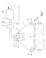
- a traversing device is shown schematically in FIG. 1.
- the traversing thread guide 8 by means of a stepping motor 4 within a Changierhubes moved back and forth.
- the transmission of the movement from Stepper motor 4 to the thread guide 8 takes place via a belt 7
- Belt 7 wraps around the pulleys 6, 9 and 11.
- the Traversing thread guide 8 is firmly connected to the endless belt 7 and is on the belt 7 between the pulleys 11 and 9 back and forth brought forth.
- the pulley 11 is rotatably mounted on an axis 12, the pulley 9 is rotatably mounted on the axis 10.
- the Pulley 6 is attached to a rotor shaft 5, which by means of a
- the rotor of the stepper motor 4 is driven with an alternating direction of rotation.
- the stepper motor 4 is controlled via a control unit 22.
- the control unit 22 has a converter 2 and one Flow control device 1.
- the flow control device 1 is with a Control line 23 and a signal line 24 with the converter 2 connected.
- the flow control device 1 is connected to a sensor 3, which senses the position of the rotor or the rotor shaft 5.
- the Flow control device also has an input for the transmission of Target values for the change.
- a winding spindle 15 is arranged below the belt drive, on the a sleeve 14 is attached.
- a coil 13 is placed on the sleeve 14 wrapped.
- a thread from the traversing thread guide 8 along the Coil surface moved back and forth.
- the flow control device 1 the stepper motor 4 for each traversing thread guide position Field sizes for influencing the rotor can be specified.
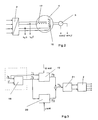
- the operation of the stepper motor can be described as follows using the schematic illustration shown in FIG. 2.
- the stepping motor 4 has at least two windings 16 and 17 arranged offset by 90 ° to one another.
- the windings 16 and 17 are alternately controlled by a converter 2 according to a predetermined time sequence.
- a magnetic field with a magnetic flux ⁇ S builds up in the windings.
- a load current (stator current) i S flows in windings.
- a rotor (not shown here) mounted in the middle of the windings will move with its permanent magnetic field.
- a sensor 3 is attached to the stepper motor to detect the position of the rotor.
- the sensor 3 is designed so that the number of steps of the sensor can be divided in whole numbers by the number of pole pairs of the step motor.
- His signal can thus be used for position control of the rotor as well as for stator flux determination.
- Particularly simple relationships result when a gearwheel is used whose number of teeth is identical to the number of pole pairs of the motor.
- a sine signal and a cosine signal are obtained by means of two field plates, which have an offset of 90 ° in relation to the tooth pitch. If you bring these signals into phase equilibrium with the rotor, you get my normalized rotor flux signal.
- the instantaneous stator current i S and the sensor signal ⁇ are then - as shown in FIG. 3 - given to a converter 18 of the flow control.
- the flow control device is shown schematically in FIG. 3. Vector sizes are indicated by an arrow.
- the converter 18 determines an actual value of the stator flux ⁇ S from the stator current and the sensor signal ⁇ .
- the actual value of the stator flux is then fed to a flux regulator 20 and at the same time to a torque regulator 19.
- a comparison is made directly at the controller input between a predetermined setpoint value of the stator flow with the instantaneous actual value of the stator flow.
- the flux controller 20 will generate a voltage signal which is applied to a pulse width modulator 21 which is connected to the converter 2.
- a comparison is made in the torque controller 19 between a predetermined target value of the torque and the actual value of the torque of the stepping motor.
- the actual torque is determined from the given values of the stator current i S and the stator flux ⁇ S. If there is a deviation, the torque controller 19 likewise generates a voltage signal which is fed to the pulse width modulator 21.
- the stator voltage u S is composed of a torque-forming component u M and a flux-forming component u ⁇ , the connection of which will be discussed in more detail later.
- the equivalent circuit diagram shown in FIG. 4 and the pointer diagram shown in FIG. 5 are also used to describe the stepping motor.
- the machine sizes are understood as space pointers in a fixed coordinate system, the ⁇ axis of the coordinate system coinciding with the winding axis of the machine and the ⁇ axis being orthogonal to the ⁇ axis.
- p is the number of pole pairs of the stepper motor
- ⁇ is the angle between the stator and rotor flux space pointer.
- the rotor flux cannot be influenced in its amplitude because of the permanent excitation. Its position only depends on the position of the rotor.
- the tip of the stator flow space pointer should be guided on a circular path. This can be achieved in that a voltage space vector uM is connected to the winding, the direction of which is orthogonal to the stator flow direction. Since the stator flux ⁇ S is essentially an integral of the stator voltage, such a voltage space pointer sets the stator flow space pointer ⁇ S in rotation. However, this voltage space pointer alone can only influence the angular velocity ⁇ , but not the amplitude of the stator flux. Therefore a further voltage space vector u ⁇ is required which points in the direction of the stator flow space vector ⁇ S.
- the stator voltage u S is thus the sum of the two components u M and u ⁇ .
- stator flux in the stepper motor can thus be determined or controlled in its amplitude and in its phase position by the stator voltage u S.
- the output signal of the stator voltage can be used directly as an input signal of a pulse width modulator after appropriate standardization. It should be noted that the voltage space pointer can only be influenced in the periods in which the converter is still clocking.
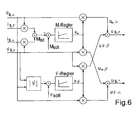
- stator flow can now be a flow controller or a Torque regulator are abandoned.
- FIG. 6 shows a block diagram of a combined control of a stator flux and the torque.
Landscapes
- Physics & Mathematics (AREA)
- Electromagnetism (AREA)
- Engineering & Computer Science (AREA)
- Microelectronics & Electronic Packaging (AREA)
- Control Of Stepping Motors (AREA)
- Winding Filamentary Materials (AREA)
- Manufacture Of Motors, Generators (AREA)
Claims (13)
- Procédé de commande d'un dispositif d'ensouplage croisé, dans lequel un guide-fil va-et-vient (8) du dispositif d'ensouplage croisé est entraíné oscillant à l'intérieur d'une course d'ensouplage par un moteur pas à pas (4) commandable et dans lequel le guide-fil va-et-vient (8) a sa position et sa vitesse déterminées par un rotor du moteur pas à pas (4), le rotor se déplaçant à l'intérieur d'un stator du moteur pas à pas (4) avec plusieurs enroulements,
caractérisé en ce qu'on produit en continu une tension statorique (uS) au moyen d'un dispositif de commande de flux et on la fournit au moteur pas à pas (4) de telle sorte que le mouvement du rotor est commandé par un flux statorique (ΨS) déterminé par la tension statorique (uS). - Procédé selon la revendication 1,
caractérisé en ce qu'on détermine en continu un couple réel (Mist) agissant sur le rotor,en ce qu'on fournit le couple réel (Mist) à un régulateur de couple,en ce que le régulateur de couple produit une valeur de correction de couple (kM) après une comparaison valeur réelle - valeur de consigne entre le couple réel (Mist) et un couple de consigne prescrit (Msoll) et en ce qu'on transforme la valeur de correction de couple (kM) en une tension statorique (uM). - Procédé selon la revendication 2,
caractérisé en ce qu'on calcule le couple réel (Mist) pour un flux rotorique constant (ΨR) à partir d'un courant statorique (iS) mesuré en continu et à partir d'un flux statorique réel (ΨS). - Procédé selon la revendication 3,
caractérisé en ce qu'on détermine le flux statorique réel (ΨS) à partir d'une tension statorique (uS) et à partir du courant statorique (iS) au moyen d'un circuit de calcul. - Procédé selon la revendication 3,
caractérisé en ce qu'on détermine le flux statorique réel (ΨS) à partir de la position angulaire (ϕ) du rotor et à partir du courant statorique (iS), la position angulaire (ϕ) du rotor étant mesurée par un capteur de position, et en ce qu'on calcule le flux statorique réel (ΨS) à partir du signal de capteur, à partir du flux rotorique (ΨR) et à partir du courant statorique (iS). - Procédé selon l'une des revendications 2 à 5,
caractérisé en ce qu'on détermine le couple de consigne (Msoll) à partir de la position et de la vitesse du guide-fil va-et-vient à l'intérieur de la course d'ensouplage. - Procédé selon la revendication 1,
caractérisé en ce qu'on fournit le flux statorique réel (ΨS) à un régulateur de flux, en ce que le régulateur de flux produit une valeur de correction de flux (kΨ) après une comparaison valeur réelle - valeur de consigne entre le flux statorique réel (ΨS) et un flux statorique de consigne (Ψsoll) et en ce qu'on transforme la valeur de correction de flux (kΨ) en une tension statorique (uΨ) pour la commande du moteur pas à pas. - Procédé selon l'une des revendications 1 à 7,
caractérisé en ce qu'on fournit le flux statorique réel (ΨS) au régulateur de flux, en ce que le régulateur de flux produit pour la commande du moteur pas à pas une valeur de correction de flux. (kΨ) après une comparaison valeur réelle - valeur de consigne entre le flux statorique réel (ΨS) et un flux statorique de consigne (Ψsoll) et en ce qu'on transforme la valeur de correction de flux (kΨ) et la valeur de correction de couple (kM) en une tension statorique (uS). - Procédé selon l'une des revendications 1 à 8,
caractérisé en ce qu'on fournit la tension statorique à un modulateur de largeur d'impulsion. - Procédé selon l'une des revendications 1 à 9,
caractérisé en ce que les régulateurs comportent chacun une composante proportionnelle et une composante intégrale. - Dispositif d'ensouplage croisé pour le déplacement d'un fil, comportant un guide-fil va-et-vient (8) se déplaçant en va-et-vient à l'intérieur d'une course d'ensouplage, un moteur pas à pas (4) entraínant le guide-fil va-et-vient (8) et une unité de commande (22) qui est reliée au moteur pas à pas (4) et qui commande le moteur pas à pas (4) de telle sorte que la position et la vitesse du guide-fil va-et-vient (4) sont déterminées par un rotor (5) du moteur pas à pas (4),
caractérisé en ce que l'unité de commande (22) comporte un dispositif de commande de flux (1) et un convertisseur (2), en ce que le dispositif de commande de flux (1) est relié au convertisseur (2) et en ce que le dispositif de commande de flux (1) peut produire une tension statorique et peut fournir la tension statorique au convertisseur (2) pour la commande du moteur pas à pas (4). - Dispositif d'ensouplage croisé selon la revendication 11,
caractérisé en ce que le dispositif de commande de flux (1) comporte un régulateur de couple (19) et/ou un régulateur de flux (20) dont les signaux de sortie sont fournis au convertisseur (2) au moyen d'un modulateur de largeur d'impulsion (21). - Dispositif d'ensouplage croisé selon la revendication 11 ou 12,
caractérisé en ce que le dispositif de commande de flux (1) est relié à un capteur de position (3) qui est agencé sur le moteur pas à pas (4) et qui détecte la position angulaire du rotor (5).
Applications Claiming Priority (3)
| Application Number | Priority Date | Filing Date | Title |
|---|---|---|---|
| DE19711546 | 1997-03-20 | ||
| DE19711546 | 1997-03-20 | ||
| PCT/EP1998/001504 WO1998042606A1 (fr) | 1997-03-20 | 1998-03-16 | Procede de commande d'un dispositif d'ensouplage croise |
Publications (2)
| Publication Number | Publication Date |
|---|---|
| EP0906239A1 EP0906239A1 (fr) | 1999-04-07 |
| EP0906239B1 true EP0906239B1 (fr) | 2000-11-02 |
Family
ID=7823960
Family Applications (1)
| Application Number | Title | Priority Date | Filing Date |
|---|---|---|---|
| EP98916956A Expired - Lifetime EP0906239B1 (fr) | 1997-03-20 | 1998-03-16 | Procede de commande d'un dispositif d'ensouplage croise |
Country Status (8)
| Country | Link |
|---|---|
| US (1) | US6008613A (fr) |
| EP (1) | EP0906239B1 (fr) |
| JP (1) | JP4647043B2 (fr) |
| CN (1) | CN1131839C (fr) |
| DE (1) | DE59800323D1 (fr) |
| TR (1) | TR199802005T1 (fr) |
| TW (1) | TW492944B (fr) |
| WO (1) | WO1998042606A1 (fr) |
Cited By (1)
| Publication number | Priority date | Publication date | Assignee | Title |
|---|---|---|---|---|
| DE102009022061A1 (de) | 2009-05-20 | 2010-11-25 | Oerlikon Textile Gmbh & Co. Kg | Changiereinrichtung |
Families Citing this family (15)
| Publication number | Priority date | Publication date | Assignee | Title |
|---|---|---|---|---|
| TR200000187T2 (tr) * | 1997-07-26 | 2000-11-21 | Barmag Ag | Bir dokuma ipliğini çaprazlamak için yöntem ve düzenek |
| DE29904699U1 (de) * | 1999-03-15 | 2000-09-28 | Münnekehoff, Gerd, Dipl.-Ing., 42857 Remscheid | Changiereinrichtung |
| IT1312588B1 (it) * | 1999-05-31 | 2002-04-22 | Sp El Srl | Procedimento e apparecchiatura per il controllo dell'avvolgimento difili e simili su supporti rotanti quali rocche di filati e simili. |
| ITMI20011851A1 (it) * | 2001-09-03 | 2003-03-03 | Sp El Srl | Dispositivo e apparecchiatura a guidafilo magnetico per l'avvolgimento di un filo su supporti cilindrici |
| JP3697583B2 (ja) * | 2002-01-29 | 2005-09-21 | 村田機械株式会社 | トラバース制御装置 |
| JP4711103B2 (ja) * | 2003-03-28 | 2011-06-29 | 村田機械株式会社 | 糸の巻き取り方法とその装置 |
| DE102005002409A1 (de) * | 2005-01-19 | 2006-07-27 | Saurer Gmbh & Co. Kg | Verfahren und Vorrichtung zum Bestimmen der Nullposition eines changierbaren Fadenführers |
| JP2006298499A (ja) * | 2005-04-15 | 2006-11-02 | Murata Mach Ltd | 糸のトラバース装置 |
| CN101513966B (zh) * | 2009-01-20 | 2012-01-11 | 常州工学院 | 线型收卷机 |
| JP5368205B2 (ja) * | 2009-07-24 | 2013-12-18 | Tmtマシナリー株式会社 | トラバース装置の制御装置 |
| JP5291058B2 (ja) * | 2010-08-26 | 2013-09-18 | 村田機械株式会社 | 糸の巻き取り方法とその装置 |
| JP2014094786A (ja) * | 2012-11-07 | 2014-05-22 | Murata Mach Ltd | 綾振装置およびこれを備えた巻取装置 |
| CZ304677B6 (cs) * | 2013-02-07 | 2014-08-27 | Rieter Cz S.R.O. | Způsob rozvádění navíjené příze a zařízení k jeho provádění |
| DE102018112802A1 (de) | 2018-05-29 | 2019-12-05 | Maschinenfabrik Rieter Ag | Verfahren zum Betreiben einer Textilmaschine sowie Textilmaschine |
| WO2020182980A1 (fr) * | 2019-03-14 | 2020-09-17 | Oerlikon Textile Gmbh & Co. Kg | Procédé de commande d'une pluralité de dispositifs de bobinage ainsi que machine textile |
Family Cites Families (14)
| Publication number | Priority date | Publication date | Assignee | Title |
|---|---|---|---|---|
| NL160125C (nl) * | 1967-10-28 | 1979-09-17 | Vdo Schindling | Stapmotor met een permanent-magnetisch rotor. |
| US3945581A (en) * | 1970-08-14 | 1976-03-23 | Barmag Barmer Maschinenfabrik Aktiengesellschaft | High-speed cross-winding device |
| DE2935800A1 (de) * | 1979-09-05 | 1981-04-02 | Ibm Deutschland Gmbh, 7000 Stuttgart | Quantisierte geschwindigkeitssteuerung eines schrittmotors |
| US4336484A (en) * | 1980-07-03 | 1982-06-22 | Textron, Inc. | Motor control |
| US4437619A (en) * | 1981-05-06 | 1984-03-20 | Hall Cary | Catenary controller |
| JPS63277495A (ja) * | 1987-05-09 | 1988-11-15 | Oki Electric Ind Co Ltd | ステッピングモ−タ駆動装置 |
| US4928050A (en) * | 1988-01-29 | 1990-05-22 | Canon Kabushiki Kaisha | Recorder |
| JP2524807B2 (ja) * | 1988-04-22 | 1996-08-14 | 帝人製機株式会社 | 糸条の巻取機におけるトラバ―ス装置 |
| JPH0798414B2 (ja) * | 1989-07-18 | 1995-10-25 | キヤノン株式会社 | 記録装置 |
| DE8915275U1 (de) * | 1989-12-30 | 1990-02-15 | Palitex Project-Company GmbH, 47804 Krefeld | Textilmaschine mit einer oder mehreren parallel liegenden Reihen von Fadenaufwickelaggregaten |
| EP0453622B1 (fr) * | 1990-04-23 | 1995-02-15 | Ssm Schärer Schweiter Mettler Ag | Procédé et dispositif pour enrouler un fil sur une bobine |
| JPH04312400A (ja) * | 1991-04-09 | 1992-11-04 | Seikosha Co Ltd | ステップモータの逆転駆動方法 |
| JP2692548B2 (ja) * | 1993-11-04 | 1997-12-17 | 村田機械株式会社 | ワインダの巻取制御方法 |
| DE29616651U1 (de) * | 1996-09-25 | 1998-01-29 | C + L Textilmaschinen GmbH, 88367 Hohentengen | Wickelmaschine |
-
1998
- 1998-03-05 TW TW087103236A patent/TW492944B/zh not_active IP Right Cessation
- 1998-03-16 JP JP54482798A patent/JP4647043B2/ja not_active Expired - Fee Related
- 1998-03-16 WO PCT/EP1998/001504 patent/WO1998042606A1/fr not_active Ceased
- 1998-03-16 EP EP98916956A patent/EP0906239B1/fr not_active Expired - Lifetime
- 1998-03-16 US US09/194,103 patent/US6008613A/en not_active Expired - Fee Related
- 1998-03-16 TR TR1998/02005T patent/TR199802005T1/xx unknown
- 1998-03-16 DE DE59800323T patent/DE59800323D1/de not_active Expired - Lifetime
- 1998-03-16 CN CN988003066A patent/CN1131839C/zh not_active Expired - Fee Related
Cited By (1)
| Publication number | Priority date | Publication date | Assignee | Title |
|---|---|---|---|---|
| DE102009022061A1 (de) | 2009-05-20 | 2010-11-25 | Oerlikon Textile Gmbh & Co. Kg | Changiereinrichtung |
Also Published As
| Publication number | Publication date |
|---|---|
| US6008613A (en) | 1999-12-28 |
| JP2001516319A (ja) | 2001-09-25 |
| WO1998042606A1 (fr) | 1998-10-01 |
| DE59800323D1 (de) | 2000-12-07 |
| TW492944B (en) | 2002-07-01 |
| TR199802005T1 (xx) | 2001-03-21 |
| JP4647043B2 (ja) | 2011-03-09 |
| CN1220641A (zh) | 1999-06-23 |
| CN1131839C (zh) | 2003-12-24 |
| EP0906239A1 (fr) | 1999-04-07 |
Similar Documents
| Publication | Publication Date | Title |
|---|---|---|
| EP0906239B1 (fr) | Procede de commande d'un dispositif d'ensouplage croise | |
| EP0453622B1 (fr) | Procédé et dispositif pour enrouler un fil sur une bobine | |
| EP0999992B1 (fr) | Procede et dispositif a va-et-vient pour la pose d'un fil | |
| EP1159216B1 (fr) | Guide-fil pour l'amenee traversante d'un fil a une bobine receptrice entrainee en rotation | |
| EP2068436B1 (fr) | Procédé et dispositif destinés à détecter les pertes de pas d'un moteur pas à pas | |
| DE10300106B4 (de) | Verfahren zur Steuerung des Antriebsmotors einer Traversierführung | |
| DE2219755C3 (de) | Vorrichtung zum Konstanthalten des Fadenzuges an Präzisionskreuzspulmaschinen | |
| DE102008027720A1 (de) | Verfahren zur sensorlosen Positionserfassung eines elektrischen Stell- oder Positionierantriebs mit einem Gleichstrommotor | |
| EP0768271A2 (fr) | Bobinoir pour un fil en déplacement continu | |
| DE2534239C2 (de) | Verfahren und Vorrichtung zur Bildstörung an einer Kreuzspuleinrichtung | |
| EP0853961A1 (fr) | Appareil de musculation | |
| DE19519542B4 (de) | Verfahren und Vorrichtung zur Vermeidung von Bildwicklungen | |
| EP0714162A2 (fr) | Circuit de commande d'une moteur commuté électroniquement | |
| DE10322533A1 (de) | Traversiervorrichtung und Traversiersteuervorrichtung | |
| EP3374304B1 (fr) | Procédé de commande d'un dispositif de pose de fil à roue à ailettes, dispositif de pose de fil à roue à ailettes et bobineuse | |
| EP3864746B1 (fr) | Procédé de détermination d'une position de rotor d'un moteur à courant continu sans balai | |
| WO2018072791A1 (fr) | Procédé et circuit pour commander un moteur pas à pas | |
| EP3074333A1 (fr) | Unité va-et-vient et procédé de commande d'une unité va-et-vient | |
| DE19835888B4 (de) | Verfahren zum Aufwickeln eines Fadens | |
| EP1684403B1 (fr) | Méthode et dispositif pour déterminer la position zéro d'un guide-fil traversant | |
| DE3621460A1 (de) | Drehkoerper-positionsregelgeraet | |
| EP1342688B1 (fr) | Procédé et dispositif pour bobiner un fil sur une machine pour fabriquer des bobines à spires croisées | |
| EP1883597B1 (fr) | Mecanisme de commande de deplacement de fil, notamment pour poste de travail d'une machine textile | |
| DE3225729C2 (de) | Vorrichtung zum Drehen eines schwenkbaren Maschinenelements zwischen zwei Rastpositionen | |
| EP0827267A1 (fr) | Procédé pour déterminer l'orientation du maximum du flux d'une machine synchrone à aimant permanent ou à excitation externe et dispositif pour la mise en oeuvre de ce procédé |
Legal Events
| Date | Code | Title | Description |
|---|---|---|---|
| PUAI | Public reference made under article 153(3) epc to a published international application that has entered the european phase |
Free format text: ORIGINAL CODE: 0009012 |
|
| 17P | Request for examination filed |
Effective date: 19990209 |
|
| AK | Designated contracting states |
Kind code of ref document: A1 Designated state(s): CH DE FR GB IT LI |
|
| GRAG | Despatch of communication of intention to grant |
Free format text: ORIGINAL CODE: EPIDOS AGRA |
|
| GRAG | Despatch of communication of intention to grant |
Free format text: ORIGINAL CODE: EPIDOS AGRA |
|
| GRAH | Despatch of communication of intention to grant a patent |
Free format text: ORIGINAL CODE: EPIDOS IGRA |
|
| 17Q | First examination report despatched |
Effective date: 20000216 |
|
| GRAH | Despatch of communication of intention to grant a patent |
Free format text: ORIGINAL CODE: EPIDOS IGRA |
|
| GRAA | (expected) grant |
Free format text: ORIGINAL CODE: 0009210 |
|
| AK | Designated contracting states |
Kind code of ref document: B1 Designated state(s): CH DE FR GB IT LI |
|
| REG | Reference to a national code |
Ref country code: CH Ref legal event code: EP |
|
| REG | Reference to a national code |
Ref country code: CH Ref legal event code: NV Representative=s name: HERMANN KAHLHOEFER |
|
| REF | Corresponds to: |
Ref document number: 59800323 Country of ref document: DE Date of ref document: 20001207 |
|
| GBT | Gb: translation of ep patent filed (gb section 77(6)(a)/1977) |
Effective date: 20001120 |
|
| ITF | It: translation for a ep patent filed | ||
| ET | Fr: translation filed | ||
| PLBE | No opposition filed within time limit |
Free format text: ORIGINAL CODE: 0009261 |
|
| STAA | Information on the status of an ep patent application or granted ep patent |
Free format text: STATUS: NO OPPOSITION FILED WITHIN TIME LIMIT |
|
| 26N | No opposition filed | ||
| REG | Reference to a national code |
Ref country code: GB Ref legal event code: IF02 |
|
| PGFP | Annual fee paid to national office [announced via postgrant information from national office to epo] |
Ref country code: GB Payment date: 20080326 Year of fee payment: 11 |
|
| PGFP | Annual fee paid to national office [announced via postgrant information from national office to epo] |
Ref country code: FR Payment date: 20080319 Year of fee payment: 11 |
|
| GBPC | Gb: european patent ceased through non-payment of renewal fee |
Effective date: 20090316 |
|
| REG | Reference to a national code |
Ref country code: FR Ref legal event code: ST Effective date: 20091130 |
|
| PG25 | Lapsed in a contracting state [announced via postgrant information from national office to epo] |
Ref country code: GB Free format text: LAPSE BECAUSE OF NON-PAYMENT OF DUE FEES Effective date: 20090316 Ref country code: FR Free format text: LAPSE BECAUSE OF NON-PAYMENT OF DUE FEES Effective date: 20091123 |
|
| PGFP | Annual fee paid to national office [announced via postgrant information from national office to epo] |
Ref country code: CH Payment date: 20160318 Year of fee payment: 19 |
|
| PGFP | Annual fee paid to national office [announced via postgrant information from national office to epo] |
Ref country code: DE Payment date: 20160331 Year of fee payment: 19 |
|
| PGFP | Annual fee paid to national office [announced via postgrant information from national office to epo] |
Ref country code: IT Payment date: 20160331 Year of fee payment: 19 |
|
| REG | Reference to a national code |
Ref country code: DE Ref legal event code: R119 Ref document number: 59800323 Country of ref document: DE |
|
| REG | Reference to a national code |
Ref country code: CH Ref legal event code: PL |
|
| PG25 | Lapsed in a contracting state [announced via postgrant information from national office to epo] |
Ref country code: DE Free format text: LAPSE BECAUSE OF NON-PAYMENT OF DUE FEES Effective date: 20171003 |
|
| PG25 | Lapsed in a contracting state [announced via postgrant information from national office to epo] |
Ref country code: CH Free format text: LAPSE BECAUSE OF NON-PAYMENT OF DUE FEES Effective date: 20170331 Ref country code: IT Free format text: LAPSE BECAUSE OF NON-PAYMENT OF DUE FEES Effective date: 20170316 Ref country code: LI Free format text: LAPSE BECAUSE OF NON-PAYMENT OF DUE FEES Effective date: 20170331 |