EP0906643B1 - Dispositif de connexion electromecanique - Google Patents
Dispositif de connexion electromecanique Download PDFInfo
- Publication number
- EP0906643B1 EP0906643B1 EP97929250A EP97929250A EP0906643B1 EP 0906643 B1 EP0906643 B1 EP 0906643B1 EP 97929250 A EP97929250 A EP 97929250A EP 97929250 A EP97929250 A EP 97929250A EP 0906643 B1 EP0906643 B1 EP 0906643B1
- Authority
- EP
- European Patent Office
- Prior art keywords
- connecting device
- switching mechanism
- electromechanical connecting
- parts
- tripping
- Prior art date
- Legal status (The legal status is an assumption and is not a legal conclusion. Google has not performed a legal analysis and makes no representation as to the accuracy of the status listed.)
- Expired - Lifetime
Links
- 239000011324 bead Substances 0.000 claims description 14
- 230000007246 mechanism Effects 0.000 claims 21
- 230000005291 magnetic effect Effects 0.000 description 7
- 230000005294 ferromagnetic effect Effects 0.000 description 4
- BGPVFRJUHWVFKM-UHFFFAOYSA-N N1=C2C=CC=CC2=[N+]([O-])C1(CC1)CCC21N=C1C=CC=CC1=[N+]2[O-] Chemical compound N1=C2C=CC=CC2=[N+]([O-])C1(CC1)CCC21N=C1C=CC=CC1=[N+]2[O-] BGPVFRJUHWVFKM-UHFFFAOYSA-N 0.000 description 3
- 238000000926 separation method Methods 0.000 description 3
- 238000010276 construction Methods 0.000 description 2
- 238000011161 development Methods 0.000 description 2
- 230000018109 developmental process Effects 0.000 description 2
- 230000003993 interaction Effects 0.000 description 2
- 230000002093 peripheral effect Effects 0.000 description 2
- 230000000295 complement effect Effects 0.000 description 1
- 230000006378 damage Effects 0.000 description 1
- 230000005611 electricity Effects 0.000 description 1
- 238000005516 engineering process Methods 0.000 description 1
- 238000007373 indentation Methods 0.000 description 1
- 230000014759 maintenance of location Effects 0.000 description 1
- 238000012806 monitoring device Methods 0.000 description 1
Images



Classifications
-
- H—ELECTRICITY
- H01—ELECTRIC ELEMENTS
- H01R—ELECTRICALLY-CONDUCTIVE CONNECTIONS; STRUCTURAL ASSOCIATIONS OF A PLURALITY OF MUTUALLY-INSULATED ELECTRICAL CONNECTING ELEMENTS; COUPLING DEVICES; CURRENT COLLECTORS
- H01R13/00—Details of coupling devices of the kinds covered by groups H01R12/70 or H01R24/00 - H01R33/00
- H01R13/62—Means for facilitating engagement or disengagement of coupling parts or for holding them in engagement
- H01R13/6205—Two-part coupling devices held in engagement by a magnet
-
- H—ELECTRICITY
- H01—ELECTRIC ELEMENTS
- H01R—ELECTRICALLY-CONDUCTIVE CONNECTIONS; STRUCTURAL ASSOCIATIONS OF A PLURALITY OF MUTUALLY-INSULATED ELECTRICAL CONNECTING ELEMENTS; COUPLING DEVICES; CURRENT COLLECTORS
- H01R13/00—Details of coupling devices of the kinds covered by groups H01R12/70 or H01R24/00 - H01R33/00
- H01R13/64—Means for preventing incorrect coupling
Definitions
- the invention relates to an electromechanical connecting device according to the preamble of claim 1 Art.
- a connecting device of this type is in EP 0 573 471 B1.
- the connection device Through this known connection device, the from a switching device, the Function of a conventional socket takes over, and a release device, the function of a with a Connected consumer takes over, is, will created a connection device that is very low Has depth and the high Meets security requirements.
- the present invention is based on the object a further improvement of the electromechanical mentioned at the beginning To achieve connection device, in particular a further increase in security or a Avoidance of incorrect switching that leads to short circuits can.
- this task is characterized by Part of claim 1 mentioned features solved.
- the centering members according to the invention ensure that the switching device and the release device only in a certain position and a certain Position of the contact elements to each other can be brought that a current flow takes place. This means that the contact elements or contact poles cannot be interchanged. This measure is special when using the electromechanical connection device for the DC area and thereby especially for the low voltage range for controls, Suitable for computers and the like, since there is no confusion between the positive and negative poles. Otherwise would be short circuits and the associated destruction of Components the result.
- centering members have at least a head start in the End face of a part are provided, in addition there is a cantilever that is superior to the lead can, which a correspondingly adapted recess or additional trough in the front of the other device assigned.
- Protrusions and indentations required for the stated purpose can be relatively flat and do not lead or only insignificantly to an increase in size.
- a very advantageous development of the centering members may be that the device as a bulging, Partial ring bead arranged in the outer region of the end face is formed in the electrical connection in a partial ring groove in terms of shape and position the other facility.
- a simple solution to the twist when loosening the Switching device from the triggering device can be that the partial ring bead with the Provide cant and the trough accordingly in the Partial ring groove is formed.
- the contact elements in the Switching device and the release device of the coded magnet separately.
- the electromechanical connection device consists of a switching device 1, the function of a conventional Socket replaced and generally at one desired location is firmly installed, and from a triggering device 2, the function of a conventional Plug replaced, which is generally with a consumer connected or which is directly to the consumer is arranged.
- the embodiment shown is particularly for the Low voltage range, e.g. 12 volts, and suitable for direct current. Of course, it is also fundamental suitable for higher voltages and also for alternating current.
- the switching device 1 and the trigger device 2 are with regard to their construction principle or their circuit coded magnets constructed similar to that in EP 0 573 471 Bl device described.
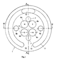
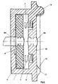
- the switching device 1 thus has a closed structural unit with a housing 3. At rest, i.e. if the triggering device 2 is not on the switching device 1 is placed, is a work slide 4 on the switching magnet 5 arranged in the form of coded magnetic parts 5a - 5d are, by a ferromagnetic retaining plate 6th held on the bottom of the housing 3.
- the coded Magnetic parts 5a - 5d in the central or inner area the switching device 1 arranged such that each on the side facing the release device 2 Adjacent north and south poles. In this way you get a coded switching magnet 5 with two north and two south poles in a particular arrangement that only in the sense of an attraction with the opposite polarized magnetic parts interact.
- Return springs 7 provide together with the ferromagnetic Retaining plate 6 for resetting the work carriage 4 after separation of the trigger device 2 from the switching device 1.
- each two coaxial contact parts 8a and 8b for the plus pole and contact parts 9a and 9b for the Negative pole provided.
- the contact parts 8a and 9a are on arranged or connected to the work carriage 4 and at the same time provide the respective contact with the leads to the switching device 1 ago.
- the Contact parts 8b and 9b are located in the switching device prepared end face 10 of the switching device 1. They are of the encoded magnetic parts 5a - 5d, however Cut.
- the switching device 1 On the end face 10 facing the triggering device the switching device 1 is located in the outer peripheral region a projection which is formed as a partial ring bead 11 can be.
- the partial ring bead 11 extends for example over 330 degrees. This means it stays corresponding free space 12 of approximately 30 degrees.
- an elevation 13 Diametrically opposite the free space 12 is in the partial ring bead 11 an elevation 13 which also extends over an angular range extends from about 30 degrees.
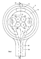
- the triggering device 2 shown in FIGS. 4 and 5 is in the same circumferential area with one to the partial ring bead 11 complementary or adapted recess, the can be designed as a partial annular groove 14 provided.
- the Partial ring groove 14 extends like the partial ring bead 11 over a range of approximately 330 degrees. There is also a Freedom 15 in a width of about 30 degrees in front. Opposite the free space 15 is in the partial ring groove 14 a deeper trough 16, which is also over extends an angular range of approximately 30 degrees.
- the release device 2 also has coded release magnets 17 with release magnet parts 17a to 17d.
- the polarities the release magnet parts 17a to 17d are selected so that when the trigger device 2 is placed on the Switching device (see Fig. 6) each north and South Poles are opposite, so a corresponding attraction is exercised on the work slide 4.
- the contact elements 18 and 19 under the bias of a spring device 22 designed such that the correspondingly resilient stored contact elements 18 and 19 from the to Switching device 1 facing end face 23 of the triggering device 2 protrude slightly.
- the release device 2 is in two parts with a cover 24 on the side facing away from the end face 23 Side.
- a cover 24 When removing the cover 24 is a Access to cables 20 and 21 and contact elements 18 and 19, as well as the trigger magnet 17 possible.
- the front end in the form of a Loop 26 resiliently over the front end face 23 in the area of a centering lug 27 of the release device 2 protrudes.
- One or more along the peripheral wall of the Tripping device arranged earth springs 25 act this way when the switching device 1 is coupled with the triggering device 2 with an earthing ring 28 Switching device 1 together (see Fig. 6).
- Fig. 6 shows the switching device 1 and the triggering device 2 in the connected state, being electricity from a power source, not shown, via the contact parts 8a, 8b and 9a, 9b on the contact elements 18 and 19 is transmitted.
- the trigger device 2 the switching device 1 is placed, the work carriage 4 by the magnetic force of the coded magnets 5 and 17 from its rest position from the ferromagnetic retention plate 6 lifted off.
- the electromechanical connecting device For the electromechanical connecting device according to the invention numerous applications are possible. Just for example computer technology should be mentioned here.
- the switching device 1 e.g. be installed in the dashboard 29 can. As can be seen, the switching device is only slightly over the front of the dashboard and the construction depth is also very small.
Landscapes
- Details Of Connecting Devices For Male And Female Coupling (AREA)
- Coupling Device And Connection With Printed Circuit (AREA)
Claims (11)
- Dispositif de connexion électromécanique avec un organe de couplage, pouvant être relié à une source de courant au moyen de contacts d'alimentation en courant, présentant des aimants de commutation munis d'éléments magnétiques codés disposés sur un chariot de travail, positionné dans un boítier en tant qu'unité de construction fermée, et qui est relié à un dispositif de déclenchement, présentant des aimants de déclenchement avec des éléments magnétiques codés, pouvant être relié de manière électrique à un utilisateur, par lequel, en reliant les deux dispositifs, les aimants de commutation sont amenés d'une position de repos à une position de travail contre une force de retenue, et ainsi la connexion électrique entre le dispositif de commutation et le dispositif de déclenchement est établie par des éléments de contact,
caractérisé en ce que
l'organe de couplage (1) et le dispositif de déclenchement (2) sont munis d'éléments de centrage sur leurs faces avant opposées (10, 23), de façon à ce que la connexion électrique entre l'organe de couplage (1) et le dispositif de déclenchement (2) ne puisse se faire constamment qu'en une position définie des éléments de contact (8, 9). - Dispositif de connexion électromécanique selon la revendication 1,
caractérisé en ce que
il est conçu pour les courants continus de basse tension. - Dispositif de connexion électromécanique selon la revendication 1 ou 2,
caractérisé en ce que
les éléments de centrage présentent au moins une saillie (11) sur la face avant (10, 23) d'une des pièces et au moins une cavité (14) adaptée à la saillie (11) sur la face avant (10, 23) de l'autre pièce. - Dispositif de connexion électromécanique selon la revendication 3,
caractérisé en ce que
le dispositif (1, 2) muni d'au moins une saillie (11) présente une surélévation (13) dépassant la saillie (11), s'adaptant à une cavité (16) adaptée à la face avant (10, 23) de l'autre dispositif (1, 2). - Dispositif de connexion électromécanique selon la revendication 3 ou 4,
caractérisé en ce que
la saillie (11) est formée par un tore partiel (11) en surépaisseur, positionné dans le secteur extérieur de l'une des faces avant (10, 23) située, lors de la connexion électrique, dans une rainure partielle d'un anneau (14), adaptée à l'autre dispositif (1, 2) dans sa forme et sa position. - Dispositif de connexion électromécanique selon les revendications 4 et 5,
caractérisé en ce que
le tore partiel (11) est muni de la surélévation (13), et en ce que la cavité (16) est logée dans la rainure partielle de l'anneau (14). - Dispositif de connexion électromécanique selon l'une des revendications 1 à 6,
caractérisé en ce que
les aimants codés (5) composés de plusieurs éléments magnétiques avec des polarités différentes sont disposés respectivement dans la partie centrale du dispositif de connexion (1) ou du dispositif de déclenchement (2). - Dispositif de connexion électromécanique selon l'une des revendications 1 à 7,
caractérisé en ce que
les éléments de contact du dispositif de déclenchement (18, 19) sont précontraints par des dispositifs à ressorts (22) dans la direction d'une connexion électrique avec le dispositif de connexion (2). - Dispositif de connexion électromécanique selon l'une des revendications 1 à 8,
caractérisé en ce que
les éléments de contact (8, 9) du dispositif de connexion (1) présentent chacun deux éléments de contact coaxiaux (8, 9), situés l'un derrière l'autre, pour le pole positif et le pole négatif, c'est-à-dire que les premiers éléments de contact (8a, 9a) sont reliés à l'alimentation en courant et disposés sur le chariot de travail (4), et les seconds éléments de contact (8b, 9b) sont disposés dans ou sur la paroi avant (23) dirigée vers le dispositif de déclenchement (2). - Dispositif de connexion électromécanique selon l'une des revendications 1 à 9,
caractérisé en ce que
le dispositif de déclenchement est relié à sa périphérie avec au moins un ressort de masse (25), qui dépasse de la face avant (10) dirigée vers le dispositif de connexion (2), et qui agit conjointement avec un anneau de masse (28) dans le dispositif de connexion (2). - Dispositif de connexion électromécanique selon l'une des revendications 1 à 10,
caractérisé en ce que
les éléments de contact (8a, 8b, 9a, 9b et 18, 19) sont séparés des aimants codés (5, 17).
Applications Claiming Priority (3)
| Application Number | Priority Date | Filing Date | Title |
|---|---|---|---|
| DE29610996U DE29610996U1 (de) | 1996-06-22 | 1996-06-22 | Elektromechanische Verbindungsvorrichtung |
| DE29610996U | 1996-06-22 | ||
| PCT/EP1997/003262 WO1997050152A1 (fr) | 1996-06-22 | 1997-06-21 | Dispositif de connexion electromecanique |
Publications (2)
| Publication Number | Publication Date |
|---|---|
| EP0906643A1 EP0906643A1 (fr) | 1999-04-07 |
| EP0906643B1 true EP0906643B1 (fr) | 2000-04-26 |
Family
ID=8025569
Family Applications (1)
| Application Number | Title | Priority Date | Filing Date |
|---|---|---|---|
| EP97929250A Expired - Lifetime EP0906643B1 (fr) | 1996-06-22 | 1997-06-21 | Dispositif de connexion electromecanique |
Country Status (6)
| Country | Link |
|---|---|
| US (1) | US6966781B1 (fr) |
| EP (1) | EP0906643B1 (fr) |
| AU (1) | AU3342597A (fr) |
| DE (2) | DE29610996U1 (fr) |
| ES (1) | ES2147675T3 (fr) |
| WO (1) | WO1997050152A1 (fr) |
Cited By (1)
| Publication number | Priority date | Publication date | Assignee | Title |
|---|---|---|---|---|
| DE102014209877A1 (de) * | 2014-05-23 | 2015-11-26 | Siemens Aktiengesellschaft | Magnetisch codierter elektrischer Schaltkontakt |
Families Citing this family (63)
| Publication number | Priority date | Publication date | Assignee | Title |
|---|---|---|---|---|
| DE19930642A1 (de) * | 1999-07-02 | 2001-01-04 | Magcode Ag | Elektromechanische Verbindungsvorrichtung |
| DE10135461A1 (de) * | 2001-07-20 | 2003-02-06 | Magcode Ag | Elektromechanische Verbindungsvorrichtung |
| US7600301B2 (en) | 2002-06-19 | 2009-10-13 | Telezygology, Inc. | Fixing and release systems and fastener networks |
| DE10242664B4 (de) * | 2002-09-13 | 2012-04-19 | Rosenberger Hochfrequenztechnik Gmbh & Co. Kg | Elektrisches Verbindungssystem |
| DE102004004016A1 (de) * | 2004-01-20 | 2005-08-04 | E.G.O. Elektro-Gerätebau GmbH | Magnetisch aktivierte Kontaktiereinrichtung |
| DE102005018275A1 (de) * | 2005-04-14 | 2006-10-19 | E.G.O. Elektro-Gerätebau GmbH | Bedienvorrichtung |
| US7025597B1 (en) * | 2005-06-21 | 2006-04-11 | Chienti Enterprise Co., Ltd. | Battery conducting device for motorized scooter |
| US7351066B2 (en) * | 2005-09-26 | 2008-04-01 | Apple Computer, Inc. | Electromagnetic connector for electronic device |
| US7311526B2 (en) * | 2005-09-26 | 2007-12-25 | Apple Inc. | Magnetic connector for electronic device |
| US7467948B2 (en) * | 2006-06-08 | 2008-12-23 | Nokia Corporation | Magnetic connector for mobile electronic devices |
| DE102006045735A1 (de) * | 2006-09-18 | 2008-03-27 | E.G.O. Elektro-Gerätebau GmbH | Bedienvorrichtung für ein Elektrogerät und Bedienverfahren |
| US7431603B1 (en) * | 2006-12-01 | 2008-10-07 | Ryan Joseph Szmidt | Electrical wire connector |
| TW200840160A (en) * | 2007-03-21 | 2008-10-01 | Asustek Comp Inc | Electrical connection mechanism between a body and a base of an electronic device |
| US7762817B2 (en) * | 2008-01-04 | 2010-07-27 | Apple Inc. | System for coupling interfacing parts |
| US7931472B2 (en) * | 2008-01-07 | 2011-04-26 | Arnon Haim David | Apparatus for transferring electric power from a mobile unit placed in various orientation on a stationary unit |
| US7771202B2 (en) * | 2008-01-07 | 2010-08-10 | Einam Yitzhak Amotz | Apparatus for transferring alternating current electrical power |
| US7841776B2 (en) | 2008-09-30 | 2010-11-30 | Apple Inc. | Magnetic connector with optical signal path |
| US9791634B2 (en) | 2008-09-30 | 2017-10-17 | Apple Inc. | Magnetic connector with optical signal path |
| DE102008051183A1 (de) * | 2008-10-14 | 2010-04-15 | Rosenberger Hochfrequenztechnik Gmbh & Co. Kg | Elektromechanisches Verbindungssystem |
| EP2207241A3 (fr) * | 2008-12-23 | 2013-04-03 | Einam Yizhak Amotz | Appareil et procédé de transfert d'alimentation d'une unité stationnaire vers une unité mobile |
| US7736151B1 (en) * | 2009-03-19 | 2010-06-15 | Hamilton Beach Brands, Inc. | Electrical connector for a kitchen appliance |
| US7871272B2 (en) * | 2009-03-20 | 2011-01-18 | Casco Products Corporation | Sliding window magnetic electrical connector |
| TW201037913A (en) * | 2009-04-03 | 2010-10-16 | Compal Electronics Inc | Electronic apparatus and connector thereof |
| DE102009048494A1 (de) * | 2009-09-25 | 2011-04-07 | E.G.O. Elektro-Gerätebau GmbH | Verfahren und Vorrichtung zur Bedienung eines Elektrogerätes |
| US8535088B2 (en) | 2009-10-20 | 2013-09-17 | Apple Inc. | Magnetic connector having a unitary housing |
| US8348678B2 (en) * | 2010-01-11 | 2013-01-08 | Automotive Industrial Marketing Corp. | Magnetic cable connector systems |
| US9300081B2 (en) | 2010-02-02 | 2016-03-29 | Charles Albert Rudisill | Interposer connectors with magnetic components |
| GB2477987B (en) * | 2010-02-22 | 2014-01-08 | Itt Mfg Entpr Llc | Electrical connector |
| DE102010028791A1 (de) * | 2010-05-10 | 2011-11-10 | Rosenberger Hochfrequenztechnik Gmbh & Co. Kg | Elektrisches Verbindungssystem |
| US8272876B2 (en) | 2010-07-20 | 2012-09-25 | Magnetic Innovations, L.L.C. | Magnetically enhanced electrical signal conduction apparatus and methods |
| DE102011006867A1 (de) | 2011-04-06 | 2012-10-11 | Robert Bosch Gmbh | Steckverbinder zur Direktkontaktierung auf einer Leiterplatte |
| CN102810777B (zh) * | 2011-06-01 | 2015-02-04 | 富泰华工业(深圳)有限公司 | 电源插头及与该电源插头配合使用的电源插座 |
| US8888500B2 (en) | 2011-06-30 | 2014-11-18 | Apple Inc. | Robust magnetic connector |
| US9065205B2 (en) | 2011-08-11 | 2015-06-23 | Apple Inc. | Connector insert having a cable crimp portion with protrusions and a receptacle having label in the front |
| ES2405530B2 (es) * | 2011-10-28 | 2015-02-16 | Smilics Technologies, S.L. | Sistema de conexión compacto para aparamenta de red eléctrica. |
| US9190782B2 (en) * | 2012-04-30 | 2015-11-17 | Club Car, Llc | Power connection system |
| US9225126B2 (en) * | 2013-04-09 | 2015-12-29 | Magno Plug Products Inc. | Magnetically actuated AC power connector |
| US8608502B2 (en) | 2012-05-08 | 2013-12-17 | Otter Products, Llc | Connection mechanism |
| DE102012105463A1 (de) * | 2012-06-22 | 2013-12-24 | Endress + Hauser Gmbh + Co. Kg | Kopplungssystem zum Einsatz in der Automatisierungstechnik |
| TWI479756B (zh) * | 2012-08-24 | 2015-04-01 | Hon Hai Prec Ind Co Ltd | 電源適配器及電連接器 |
| GB2509924A (en) | 2013-01-17 | 2014-07-23 | Itt Mfg Entpr Llc | Breakaway electrical connector |
| US20150201723A1 (en) | 2013-02-01 | 2015-07-23 | Treefrog Developments, Inc. | Encasements for an electronic device having a biometric scanner |
| US10680383B2 (en) | 2013-03-14 | 2020-06-09 | Apex Technologies, Inc. | Linear electrode systems for module attachment with non-uniform axial spacing |
| JP5783387B2 (ja) * | 2013-04-25 | 2015-09-24 | Smk株式会社 | 磁気接合式コネクタ |
| US20150000952A1 (en) | 2013-06-28 | 2015-01-01 | Magnetic Innovations Llc | Magnetically Enhanced Electrical Signal Conduction Cables and Methods |
| US9244211B2 (en) | 2013-07-26 | 2016-01-26 | Scott William Campbell | Illuminated garment and accessories |
| WO2015168221A1 (fr) * | 2014-04-29 | 2015-11-05 | Bretford Manufacturing, Inc. | Système d'alimentation renfoncé |
| US9570843B2 (en) * | 2014-06-13 | 2017-02-14 | Htc Corporation | Conductive structure and electronic assembly |
| DE102014216389A1 (de) * | 2014-08-19 | 2016-02-25 | BSH Hausgeräte GmbH | Bedienvorrichtung für ein Haushaltsgerät mit stabil positioniertem ringförmigen Bedienelement-Vorderteil und Haushaltsgerät mit einer derartigen Bedienvorrichtung |
| GB2531020C (en) | 2014-10-07 | 2020-09-30 | Itt Mfg Enterprises Llc | Electrical connector |
| JP6537819B2 (ja) | 2014-12-18 | 2019-07-03 | 日本航空電子工業株式会社 | コネクタ対 |
| DE102015203706B4 (de) | 2015-03-02 | 2020-03-26 | Volkswagen Aktiengesellschaft | Anordnung zur lösbaren Befestigung einer Fußmatte an einem Boden oder Bodenbelag eines Fahrzeugs |
| JP6422386B2 (ja) * | 2015-03-31 | 2018-11-14 | ニッタ株式会社 | コネクタ装置 |
| US9819099B2 (en) | 2015-08-13 | 2017-11-14 | Itt Manufacturing Enterprises Llc | Multi-part contact having a front contact portion and a rear crimp contact portion joined together at an angle by a threaded connector |
| CZ2015747A3 (cs) * | 2015-10-23 | 2016-12-28 | Petr Cuber | Magnetický spojovací člen, zejména pro příruby potrubí |
| US10056713B2 (en) * | 2016-01-22 | 2018-08-21 | Method Lights, LLC | Charger extension for elevated devices |
| CN205790773U (zh) * | 2016-05-24 | 2016-12-07 | 京东方科技集团股份有限公司 | 一种插座 |
| US10312640B2 (en) * | 2017-01-20 | 2019-06-04 | Philip Giampi | Magnetically activated power socket and plug combination |
| EP4324742A3 (fr) * | 2017-08-23 | 2024-04-17 | Amphenol Phitek Limited | Connecteur électrique |
| US10522943B1 (en) * | 2018-09-21 | 2019-12-31 | Calista A. Termini | Magnetically securing detachable electronic cable assembly and method |
| WO2020113508A1 (fr) * | 2018-12-06 | 2020-06-11 | Microsoft Technology Licensing, Llc | Fiche magnétique |
| FR3096184B1 (fr) * | 2019-05-15 | 2021-07-30 | Gulplug | Système de connexion électrique triphasée |
| US11424573B2 (en) | 2020-09-24 | 2022-08-23 | Apple Inc. | Magnetic connectors with self-centering floating contacts |
Family Cites Families (13)
| Publication number | Priority date | Publication date | Assignee | Title |
|---|---|---|---|---|
| US2573920A (en) * | 1949-04-25 | 1951-11-06 | Mcleod William | Coupling actuated magnetic switch |
| US3261944A (en) * | 1965-04-12 | 1966-07-19 | John F Sherwood | Magnetic switch |
| US3521216A (en) * | 1968-06-19 | 1970-07-21 | Manuel Jerair Tolegian | Magnetic plug and socket assembly |
| US4004298A (en) * | 1975-03-31 | 1977-01-25 | Sinai Hospital Of Detroit | Magnetically aligned releasable connector |
| DE2643031A1 (de) | 1976-09-24 | 1978-03-30 | Ante Raguz | Sicherheits-steckvorrichtung |
| US4317969A (en) * | 1978-09-01 | 1982-03-02 | Hannes Riegler | Electrical line-connector |
| DE3577024D1 (de) * | 1984-02-08 | 1990-05-10 | Tzivanidis Pavlos | Elektrische sicherheitssteckverbindung. |
| DE3517830A1 (de) * | 1985-05-17 | 1986-11-20 | Geka-Werk Reinhold Klein KG, 3573 Gemünden | Anschlussgeraet fuer ein schnurloses elektrogeraet |
| CH681121A5 (en) | 1990-10-10 | 1993-01-15 | Erwin Meister | Low current electrical connector e.g. for recording-playback system - has base with circuit plate and contacts retained against plug section by field generated by permanent |
| WO1992016002A1 (fr) | 1991-02-27 | 1992-09-17 | Eberhard Beck | Dispositif de connexion electromecanique |
| DE19512335C1 (de) * | 1995-04-01 | 1996-08-29 | Fritsch Klaus Dieter | Elektromechanische Verbindungsvorrichtung |
| DE19512334C1 (de) * | 1995-04-01 | 1996-08-29 | Fritsch Klaus Dieter | Elektromechanische Verbindungsvorrichtung |
| DE29516069U1 (de) | 1995-10-06 | 1995-12-14 | Bullinger, Achim, 89542 Herbrechtingen | Aufnahmevorrichtung für eine elektrische Lichtquelle |
-
1996
- 1996-06-22 DE DE29610996U patent/DE29610996U1/de not_active Expired - Lifetime
-
1997
- 1997-06-21 WO PCT/EP1997/003262 patent/WO1997050152A1/fr not_active Ceased
- 1997-06-21 ES ES97929250T patent/ES2147675T3/es not_active Expired - Lifetime
- 1997-06-21 US US09/214,034 patent/US6966781B1/en not_active Expired - Lifetime
- 1997-06-21 AU AU33425/97A patent/AU3342597A/en not_active Abandoned
- 1997-06-21 EP EP97929250A patent/EP0906643B1/fr not_active Expired - Lifetime
- 1997-06-21 DE DE59701522T patent/DE59701522D1/de not_active Expired - Lifetime
Cited By (1)
| Publication number | Priority date | Publication date | Assignee | Title |
|---|---|---|---|---|
| DE102014209877A1 (de) * | 2014-05-23 | 2015-11-26 | Siemens Aktiengesellschaft | Magnetisch codierter elektrischer Schaltkontakt |
Also Published As
| Publication number | Publication date |
|---|---|
| DE59701522D1 (de) | 2000-05-31 |
| WO1997050152A1 (fr) | 1997-12-31 |
| DE29610996U1 (de) | 1996-09-12 |
| ES2147675T3 (es) | 2000-09-16 |
| US6966781B1 (en) | 2005-11-22 |
| AU3342597A (en) | 1998-01-14 |
| EP0906643A1 (fr) | 1999-04-07 |
Similar Documents
| Publication | Publication Date | Title |
|---|---|---|
| EP0906643B1 (fr) | Dispositif de connexion electromecanique | |
| EP0819326B1 (fr) | Dispositif de connexion electromecanique | |
| EP0819327B1 (fr) | Dispositif de connexion electromecanique | |
| EP1342295B1 (fr) | Dispositif de raccordement electromecanique | |
| DE69021995T2 (de) | Gleichstromschaltgerät. | |
| EP1194983B1 (fr) | Dispositif de connexion electromecanique | |
| EP0922315B1 (fr) | Dispositif de connexion electromecanique | |
| EP0573471B1 (fr) | Dispositif de connexion electromecanique | |
| DE2246538A1 (de) | Einrastteil zur polunverwechselbaren kodierung von steckverbindern | |
| EP2338210B1 (fr) | Système de liaison électromécanique | |
| DE2052040C3 (de) | Druckfest geschützte Sicherung | |
| DE10152684A1 (de) | Elektrischer Akkumulator | |
| DE19740490C1 (de) | Trennschalter | |
| DE19738074C2 (de) | Notabschaltvorrichtung, insbesondere bei Elektro-Flurförderzeugen zum Trennen der Verbindung zwischen Motor oder dessen Steuereinheit und den Antriebsbatterien für diesen | |
| DE102005017902A1 (de) | Lasttrennschalter sowie Schaltanlage mit Lasttrennschalter | |
| DE102006004254B3 (de) | Mehrpoliges Schaltgerät mit Zusatzgehäuse | |
| DE3013985C2 (fr) | ||
| DE2323386B2 (de) | Ringkabelstationsschalter | |
| DE29818195U1 (de) | Schalter zur wahlweisen Parallel- oder Reihenschaltung | |
| DE7015186U (de) | Sicherheitssteckdose. | |
| DD290743A5 (de) | Elektroschalter, insbesondere fuer waschmaschinen | |
| DE8910427U1 (de) | Schalter mit funkengeschützter Lastumschaltung | |
| DE7420795U (fr) | ||
| DE2418930A1 (de) | Gleichstrombetaetigter elektromagnetischer schalter | |
| DE1073063B (de) | Druckknopfschalter, insbesondere Einbaudruckknopfschalter |
Legal Events
| Date | Code | Title | Description |
|---|---|---|---|
| PUAI | Public reference made under article 153(3) epc to a published international application that has entered the european phase |
Free format text: ORIGINAL CODE: 0009012 |
|
| 17P | Request for examination filed |
Effective date: 19990113 |
|
| AK | Designated contracting states |
Kind code of ref document: A1 Designated state(s): DE ES FR GB IT DE ES FR GB IT |
|
| RIN1 | Information on inventor provided before grant (corrected) |
Inventor name: NEIDLEIN, HERMANN Inventor name: FRITSCH, KLAUS-DIETER Inventor name: BULLINGER, ACHIM; C/O FRAU RUTH BULLINGER |
|
| GRAG | Despatch of communication of intention to grant |
Free format text: ORIGINAL CODE: EPIDOS AGRA |
|
| 17Q | First examination report despatched |
Effective date: 19990629 |
|
| GRAG | Despatch of communication of intention to grant |
Free format text: ORIGINAL CODE: EPIDOS AGRA |
|
| GRAH | Despatch of communication of intention to grant a patent |
Free format text: ORIGINAL CODE: EPIDOS IGRA |
|
| GRAH | Despatch of communication of intention to grant a patent |
Free format text: ORIGINAL CODE: EPIDOS IGRA |
|
| GRAA | (expected) grant |
Free format text: ORIGINAL CODE: 0009210 |
|
| AK | Designated contracting states |
Kind code of ref document: B1 Designated state(s): DE ES FR GB IT |
|
| REF | Corresponds to: |
Ref document number: 59701522 Country of ref document: DE Date of ref document: 20000531 |
|
| ITF | It: translation for a ep patent filed | ||
| GBT | Gb: translation of ep patent filed (gb section 77(6)(a)/1977) |
Effective date: 20000707 |
|
| ET | Fr: translation filed | ||
| REG | Reference to a national code |
Ref country code: ES Ref legal event code: FG2A Ref document number: 2147675 Country of ref document: ES Kind code of ref document: T3 |
|
| PLBE | No opposition filed within time limit |
Free format text: ORIGINAL CODE: 0009261 |
|
| STAA | Information on the status of an ep patent application or granted ep patent |
Free format text: STATUS: NO OPPOSITION FILED WITHIN TIME LIMIT |
|
| 26N | No opposition filed | ||
| REG | Reference to a national code |
Ref country code: GB Ref legal event code: IF02 |
|
| REG | Reference to a national code |
Ref country code: FR Ref legal event code: PLFP Year of fee payment: 20 |
|
| PGFP | Annual fee paid to national office [announced via postgrant information from national office to epo] |
Ref country code: ES Payment date: 20160617 Year of fee payment: 20 Ref country code: GB Payment date: 20160627 Year of fee payment: 20 |
|
| PGFP | Annual fee paid to national office [announced via postgrant information from national office to epo] |
Ref country code: IT Payment date: 20160427 Year of fee payment: 20 Ref country code: FR Payment date: 20160623 Year of fee payment: 20 |
|
| PGFP | Annual fee paid to national office [announced via postgrant information from national office to epo] |
Ref country code: DE Payment date: 20160707 Year of fee payment: 20 |
|
| REG | Reference to a national code |
Ref country code: DE Ref legal event code: R071 Ref document number: 59701522 Country of ref document: DE |
|
| REG | Reference to a national code |
Ref country code: GB Ref legal event code: PE20 Expiry date: 20170620 |
|
| PG25 | Lapsed in a contracting state [announced via postgrant information from national office to epo] |
Ref country code: GB Free format text: LAPSE BECAUSE OF EXPIRATION OF PROTECTION Effective date: 20170620 |
|
| REG | Reference to a national code |
Ref country code: ES Ref legal event code: FD2A Effective date: 20180508 |
|
| PG25 | Lapsed in a contracting state [announced via postgrant information from national office to epo] |
Ref country code: ES Free format text: LAPSE BECAUSE OF EXPIRATION OF PROTECTION Effective date: 20170622 |