EP0906800B1 - Méthode et dispositif pour la fabrication des arbres creux ayant des bosses radiales par le procédé de formage par pression interne - Google Patents
Méthode et dispositif pour la fabrication des arbres creux ayant des bosses radiales par le procédé de formage par pression interne Download PDFInfo
- Publication number
- EP0906800B1 EP0906800B1 EP98116383A EP98116383A EP0906800B1 EP 0906800 B1 EP0906800 B1 EP 0906800B1 EP 98116383 A EP98116383 A EP 98116383A EP 98116383 A EP98116383 A EP 98116383A EP 0906800 B1 EP0906800 B1 EP 0906800B1
- Authority
- EP
- European Patent Office
- Prior art keywords
- semi
- finished product
- tool
- protrusions
- axial
- Prior art date
- Legal status (The legal status is an assumption and is not a legal conclusion. Google has not performed a legal analysis and makes no representation as to the accuracy of the status listed.)
- Expired - Lifetime
Links
- 238000000034 method Methods 0.000 title claims abstract description 22
- 239000011265 semifinished product Substances 0.000 claims abstract description 47
- 230000008569 process Effects 0.000 claims abstract description 12
- 239000000463 material Substances 0.000 claims abstract description 10
- 238000007493 shaping process Methods 0.000 claims abstract description 3
- 238000007789 sealing Methods 0.000 claims description 15
- 239000011324 bead Substances 0.000 claims description 6
- 239000000047 product Substances 0.000 claims description 6
- 230000007246 mechanism Effects 0.000 claims description 4
- 230000007480 spreading Effects 0.000 claims description 3
- 238000003892 spreading Methods 0.000 claims description 3
- 238000003825 pressing Methods 0.000 claims description 2
- 238000004519 manufacturing process Methods 0.000 description 6
- 230000035508 accumulation Effects 0.000 description 5
- 238000009825 accumulation Methods 0.000 description 5
- 239000012530 fluid Substances 0.000 description 2
- RYGMFSIKBFXOCR-UHFFFAOYSA-N Copper Chemical compound [Cu] RYGMFSIKBFXOCR-UHFFFAOYSA-N 0.000 description 1
- 241001295925 Gegenes Species 0.000 description 1
- 229910000831 Steel Inorganic materials 0.000 description 1
- 230000005540 biological transmission Effects 0.000 description 1
- 229910052802 copper Inorganic materials 0.000 description 1
- 239000010949 copper Substances 0.000 description 1
- 238000000227 grinding Methods 0.000 description 1
- 238000010438 heat treatment Methods 0.000 description 1
- 238000003384 imaging method Methods 0.000 description 1
- 238000004898 kneading Methods 0.000 description 1
- 238000003801 milling Methods 0.000 description 1
- 238000000465 moulding Methods 0.000 description 1
- 238000012805 post-processing Methods 0.000 description 1
- 239000010959 steel Substances 0.000 description 1
Images

Classifications
-
- B—PERFORMING OPERATIONS; TRANSPORTING
- B21—MECHANICAL METAL-WORKING WITHOUT ESSENTIALLY REMOVING MATERIAL; PUNCHING METAL
- B21D—WORKING OR PROCESSING OF SHEET METAL OR METAL TUBES, RODS OR PROFILES WITHOUT ESSENTIALLY REMOVING MATERIAL; PUNCHING METAL
- B21D26/00—Shaping without cutting otherwise than using rigid devices or tools or yieldable or resilient pads, i.e. applying fluid pressure or magnetic forces
- B21D26/02—Shaping without cutting otherwise than using rigid devices or tools or yieldable or resilient pads, i.e. applying fluid pressure or magnetic forces by applying fluid pressure
- B21D26/033—Deforming tubular bodies
- B21D26/047—Mould construction
-
- B—PERFORMING OPERATIONS; TRANSPORTING
- B21—MECHANICAL METAL-WORKING WITHOUT ESSENTIALLY REMOVING MATERIAL; PUNCHING METAL
- B21D—WORKING OR PROCESSING OF SHEET METAL OR METAL TUBES, RODS OR PROFILES WITHOUT ESSENTIALLY REMOVING MATERIAL; PUNCHING METAL
- B21D15/00—Corrugating tubes
- B21D15/04—Corrugating tubes transversely, e.g. helically
- B21D15/10—Corrugating tubes transversely, e.g. helically by applying fluid pressure
-
- B—PERFORMING OPERATIONS; TRANSPORTING
- B21—MECHANICAL METAL-WORKING WITHOUT ESSENTIALLY REMOVING MATERIAL; PUNCHING METAL
- B21D—WORKING OR PROCESSING OF SHEET METAL OR METAL TUBES, RODS OR PROFILES WITHOUT ESSENTIALLY REMOVING MATERIAL; PUNCHING METAL
- B21D53/00—Making other particular articles
- B21D53/84—Making other particular articles other parts for engines, e.g. connecting-rods
- B21D53/845—Making camshafts
Definitions
- the invention relates to a method and a device for producing a hollow shaft with outer radial elevations, in particular camshaft, from a preformed Semi-finished product according to the hydroforming process, whereby during the internal high pressure forming with the tool closed Transport of material into the forming zone, the preformed elevations or Constriction beads of the semi-finished product are axially applied.
- the pipe section After closing the ends of the pipe section through the forming plunger, the pipe section with the help of a suitable Pressurized medium with high internal pressure and at the same time pressurized with axial pressure (through the forming plunger) on the pipe wall reshaped.
- the axial pressure and the internal pressure cause the pipe section to the inner contour or wall having the final shape of the hollow body of the forming tool.
- the material is used for hydroforming placed in the plastic state during the entire forming process taking into account material hardening and any tool forces is maintained.
- the invention has for its object a method and an apparatus to create the kind mentioned at the outset, with which the preformed Semi-finished products with targeted contour and shape of the mass accumulations achieve and thus elaborate post-processing, z.
- This object is achieved in that a Collection of the semi-finished product is completely included before the next one Surveys are finished.
- the invention is based on the finding that due to the internal high pressure forming of these semi-finished products Geometry difficult elongation situation with an over the uniform elongation lying circumferential expansion in the area of mass accumulation, which is a special Consideration of the material flow requires, then coped with when the Pressurization to feed the material no longer as with Internal high-pressure forming process usually takes place from the end faces of the semi-finished product, but directly via the already existing, preformed surveys or Constriction beads themselves. It can then be done gradually Finished forming by shaping the elevations in groups and thus on a section that is much smaller in relation to the total length of the semi-finished product enable so that the longitudinal expansion can be significantly reduced.
- An embodiment of the method according to the invention provides that the open Ends of the semi-finished product inserted into the tool from both sides in the hollow shaft retracting closure means, at least one of which has a feed for the pressure medium is formed, sealed, the entire semi-finished product during the introduction of the print medium over to adjacent surveys facing each other axially engaging tool means and after the hydroforming of this section the Tool means are solved, then the semi-finished product to the finished product one further step, determined by the distance between the surveys, into the Tool fed in and after the respective closing of the tool means media is introduced again.
- the surveys can thus be Pressure build-up by pushing the axial blocks to their finished contour in steps Form individual production of the recorded group of surveys.
- the semi-finished product is simultaneously with the Feed rotated into the tool. This can be done for example by means of a step-by-step workpiece feed already available manipulator achieve, the turning especially when offset over the circumference Surveys are required, as in the case of camshaft manufacture.
- a device for performing the method provides that the tool a divided one, depicting the geometry of a group of elevations on the inside Block consists in which of two axially opposite axial blocks of the first axial block on the one hand with one of the basic geometry of the elevations corresponding recess completely includes a survey and on the other hand with its end face facing the second axial block from the outside to the creates the next survey and applies it during the second Axialblock is the outside elevation adjacent to the next elevation acted upon, one arranged between the two axial blocks, the Axial blocks slidably supporting center block the semi-finished product between the two charged surveys.
- the example in Dovetail guides carried by the center block in the parting plane also subdivided axial blocks correspondingly lifted and after the handling process be closed again.
- sealing lances engage in the open ends of the semi-finished product one, at least one of which is connected to a pressure medium source Has pressure medium supply. It is recommended that the sealing lances with one pressing a sealing ring against the inner wall of the semi-finished product Spreading mechanism are formed.
- the sealing lances positioned thus close or chamber the pressure medium introduced via the feed into its effective space and limit it essentially to the respective group the surveys or constrictions to be formed.
- the sealing ring with a tie rod engaging behind an anchor, the advantageously made of an elastic plastic material radially widen and press against the inner contour of the semi-finished product. With increasing The seal supports the internal pressure in the effective space of the pressure medium supplied also yourself.
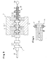
- the internal high-pressure forming machine shown is from one shown in FIG Semi-finished product 1, which is distributed over its length on the outside with several radial Surveys 2 to 9 is provided; the semifinished product 1 according to the embodiment serves as a preliminary product for a camshaft to be manufactured.
- the semifinished product 1 is at least one free end 10 by means of a manipulator (not shown) into the - different from its functional position shown in FIG. 2 - completely opened tool 11, the one divided and the geometry of a group 2, 3 or 4, 5 or 6, 7 or 8.9 of the radial elevations 2 to 9 imaging block consists of a center block 12 and two opposite, in upper and lower Slideways 13 and 14 of the center block 12 arranged, i.e. of this supported axial blocks 15, 16.
- the horizontal parting plane of the - thus two-part - Blocks 12 and 15, 16 and the vertical parting planes of the center block 12 in Reference to the axial blocks 15, 16 guided in it is the partially open one 3 according to the tool.
- the center block 12 becomes more vertical Direction and the axial blocks 15 and 16 are acted upon in the axial direction.
- the Axial blocks 15, 16 lie with their inner end faces 17 and 18 on the Outside of the - in the embodiment of FIG. 2 - group of two of the two radial elevations 8, 9. So that during hydroforming the radial elevations 8, 9 - and in the step sequence of group-wise subsequent conveying the elevations 6, 7 or 4, 5 or 2, 3 - with a local characteristic to cam 19 (cf. FIG. 3), the end faces 17, 18 of the axial blocks 15, 16 corresponding cutouts 20, which can be seen in more detail in FIG.
- the gradual group forming first axial block 16 also has one of the Basic geometry of the elevations 2 to 9 corresponding recess 21 (see FIG. 3) in its two sub-blocks, with the first one being processed Group following survey 7 or 5 or in the penultimate step survey 3 completely includes; forming the last group, i.e. of the two neighboring ones Elevations 2, 3, the recess 21 remains free.
- the one during the forming process required transport of material in the forming zone is consequently via the charged surveys 8, 9 - or in the case of inner beads, not shown Semi-finished products about this - achieved by yourself.
- Sealing lances 22 serve to seal the semifinished product 1 during the forming or 23, the retracted from the two open sides of the semi-finished product 1 and with a sealing head 24 shown in Fig. 4 to the inner contour or wall of the Semi-finished product 1 are pressed.
- This can - as for example according to FIG. 4 - by means of a cantilever projecting out of an anchor piece 25
- plastic sealing ring 27 is radially widened (see the arrows in Fig. 4).
- To introduce the pressure medium into the cam 19 to form it serving effective space according to FIG. 3 is at least one sealing lance 23 with a Pressure medium supply 28 formed, which is connected to a pressure medium source 29 is.
- the mode of operation for the hydroforming of elevations 2 to 9 - or any other number of elevations or inner beads, depending on desired finished product - through group-specific production to cam 19 one Camshaft is accordingly such that when the tool 11 is completely open, by means of the Handling manipulator, the semi-finished product 1 axially fed and thus the first Group of the elevations to be formed is fed into the tool 11. Then the center block 12 is closed, using the example of FIGS. 2 and 3 (see Fig. 3) and then the two two-part axial blocks 15, 16 to the plant the center block 12 (see FIG. 2) moved together, due to the Shape or the cutouts 20 locally shape the cams 19; the finished Cams 19 can be seen on the right in FIG. 3.
- the Lances 23 from the effective space of the introduced pressure medium.
- the blocks 12 and 14, 15 of the tool 11 move in reverse Sequence apart, whereupon the camshaft or the semifinished product 1 transported and unhindered by the manipulator at the same time can be rotated so that the tool 11 or its blocks 12 and 14, 15 in can form another cam group in the same position and in the same cycle.
Landscapes
- Engineering & Computer Science (AREA)
- Mechanical Engineering (AREA)
- Physics & Mathematics (AREA)
- Fluid Mechanics (AREA)
- Shaping Metal By Deep-Drawing, Or The Like (AREA)
- Valve-Gear Or Valve Arrangements (AREA)
- Shafts, Cranks, Connecting Bars, And Related Bearings (AREA)
- Forging (AREA)
Claims (7)
- Procédé pour la fabrication de pièces selon le procédé de formage à haute pression interne à partir d'un produit semi-fini (1) préformé, de type à arbre creux, qui présente des bosses (2 à 9) radiales extérieures ou des rétrécissements en forme de bourrelets en saillie à intérieur de l'arbre creux, les bosses (2 à 9) ou les bourrelets de rétrécissement préformés du produit semi-fini étant sollicités axialement pour le transport de la matière nécessaire dans la zone de formage pendant le formage à haute pression interne avec un outil (11) fermé, caractérisé en ce qu'une bosse (2 à 9) du produit semi-fini (1) est complètement incorporé avant que les bosses consécutives soient soumises à un formage final.
- Procédé selon la revendication 1, caractérisé en ce que les extrémités ouvertes du produit semi-fini (1) placé dans l'outil (11) sont fermées des deux côtés par des moyens de fermeture (22, 23) pénétrant dans l'arbre creux, dont au moins un est exécuté avec une alimentation (28) pour l'agent sous pression, en ce que la totalité du produit semi-fini (1), pendant l'introduction de l'agent sous pression, est déplacé axialement via des parties d'outil (15, 16) se faisant face s'agrippant à chaque fois à l'extérieur à des bosses voisines (2, 3 ; 4, 5 ; 6, 7 ; 8, 9) et en ce qu'après le formage à haute pression interne de cette section partielle, les parties d'outil (15, 16) sont lâchées, en ce que le produit semi-fini (1) est avancé, jusqu'à l'obtention du produit fini, d'un pas supplémentaire déterminé par la distance des bosses dans l'outil (11) et en ce qu'après à chaque fois la fermeture des outils (12; 15, 16), on introduit à nouveau de l'agent sous pression.
- Procédé selon la revendication 1 ou 2, en particulier pour la fabrication d'un arbre à cames à partir d'un produit semi-fini présentant des bosses radiales extérieures, caractérisé en ce que le produit semi-fini est tourné dans l'outil en même temps qu'il est avancé.
- Dispositif pour la production de pièces selon le procédé de formage à haute pression interne à partir d'un produit semi-fini préformé, de type à arbre creux, en particulier pour réaliser le procédé selon la revendication 1 ou 2, caractérisé en ce que l'outil (11) est constitué d'un bloc (12, 14, 15) présentant à l'intérieur la géométrie d'un groupe (2, 3 ou 4, 5 ou 6, 7 ou 8, 9) des bosses (2 à 9), dont, parmi deux blocs (15, 16) axiaux se faisant face, le premier bloc (16) axial entoure d'une part complètement, avec un évidement (21) correspondant à la géométrie de base des bosses (2 à 9), une bosse (7 ou 5 ou 3) et se place d'autre part avec sa face (18) dirigée vers le deuxième bloc axial (15) de l'extérieur contre la bosse suivante (8) et sollicite celle-ci, alors que le deuxième bloc axial (15) sollicite la bosse (9) voisine de la bosse suivante (8) de l'extérieur, un bloc central (12) disposé entre les deux blocs axiaux voisins (15, 16), supportant avec un mouvement de glissement les blocs axiaux (15, 16) entourant le produit semi-fini (1) entre les deux bosses sollicitées (8, 9 ou 6, 7 ou 4,5 ou 2,3).
- Dispositif selon la revendication 4, caractérisé en ce que les faces (17, 18) des blocs axiaux (15, 16) dirigés vers les bosses sollicitées (8, 9 ou 6, 7 ou 4, 5 ou 2, 3) sont formées, pour la réalisation de cames (19) d'un arbre à cames, avec une section de face (20) limitant le formage local des bosses (2 à 9).
- Dispositif selon la revendication 4 ou 5, caractérisé par des lances d'étanchéité (22, 23) s'agrippant dans les extrémités ouvertes du produit semi-fini (1), dont au moins une (23) présente une alimentation (28) en agent sous pression raccordée à une source (29) d'agent sous pression.
- Dispositif selon la revendication 6, caractérisé en ce que les lances d'étanchéité (22, 23) sont exécutées avec un mécanisme d'écartement (25, 26) comprimant un joint annulaire d'étanchéité (27) contre la paroi interne du tuyau du produit semi-fini
Applications Claiming Priority (2)
| Application Number | Priority Date | Filing Date | Title |
|---|---|---|---|
| DE19743863 | 1997-10-04 | ||
| DE19743863A DE19743863A1 (de) | 1997-10-04 | 1997-10-04 | Verfahren und Vorrichtung zum Herstellen einer Hohlwelle mit äußeren radialen Erhebungen durch Innenhochdruck-Umformung |
Publications (2)
| Publication Number | Publication Date |
|---|---|
| EP0906800A1 EP0906800A1 (fr) | 1999-04-07 |
| EP0906800B1 true EP0906800B1 (fr) | 2002-04-03 |
Family
ID=7844576
Family Applications (1)
| Application Number | Title | Priority Date | Filing Date |
|---|---|---|---|
| EP98116383A Expired - Lifetime EP0906800B1 (fr) | 1997-10-04 | 1998-08-29 | Méthode et dispositif pour la fabrication des arbres creux ayant des bosses radiales par le procédé de formage par pression interne |
Country Status (4)
| Country | Link |
|---|---|
| EP (1) | EP0906800B1 (fr) |
| AT (1) | ATE215412T1 (fr) |
| DE (2) | DE19743863A1 (fr) |
| ES (1) | ES2175576T3 (fr) |
Cited By (1)
| Publication number | Priority date | Publication date | Assignee | Title |
|---|---|---|---|---|
| DE102004030545B3 (de) * | 2004-06-24 | 2006-01-05 | Sebring Technology Gmbh | Verfahren und Vorrichtung zum Innenhochdruckformen eines Hohlprofils |
Families Citing this family (5)
| Publication number | Priority date | Publication date | Assignee | Title |
|---|---|---|---|---|
| DE102004054324A1 (de) * | 2004-11-10 | 2006-05-24 | Joachim Hermann Schondelmaier | Verfahren und Vorrichtung zum Verformen von Werkstücken |
| PL1801250T3 (pl) * | 2005-12-22 | 2018-02-28 | Viega Technology Gmbh & Co. Kg | Części konstrukcyjne ze stopu miedzi o niskiej migracji przeznaczone do instalacji mediów lub wody pitnej |
| JP4812570B2 (ja) * | 2006-09-13 | 2011-11-09 | 株式会社久保田鉄工所 | 中空異形段付軸の成形方法及びその成形装置 |
| DE102010051997A1 (de) * | 2010-11-19 | 2012-05-24 | Fraunhofer-Gesellschaft zur Förderung der angewandten Forschung e.V. | Verfahren und Vorrichtung zur Herstellung eines hohlen Bauteils und ein hohles Bauteil |
| EP2745951B1 (fr) * | 2012-12-20 | 2014-11-19 | C.R.F. Società Consortile per Azioni | Procédé pour produire un arbre à cames pour un moteur à combustion interne |
Family Cites Families (7)
| Publication number | Priority date | Publication date | Assignee | Title |
|---|---|---|---|---|
| US3015354A (en) * | 1956-12-11 | 1962-01-02 | Standard Thomson Corp | Flexible tube forming machine |
| US3704983A (en) * | 1970-12-04 | 1972-12-05 | Establissements Butin Gillet | Method of and apparatus for the formation of tubular articles |
| JPS5976634A (ja) * | 1982-10-26 | 1984-05-01 | Toshiba Corp | クランクシヤフトの製法 |
| JPS59120326A (ja) * | 1982-12-28 | 1984-07-11 | Toshiba Corp | 圧縮機等のクランクシヤフト成形方法 |
| JP2661981B2 (ja) * | 1988-09-09 | 1997-10-08 | 正信 中村 | 突起付きパイプの製造方法 |
| DE4427201C2 (de) * | 1993-11-26 | 1996-09-12 | Ges Innenhochdruckverfahren | Verfahren zur Herstellung von hohlen Nockenwellen |
| DE19622372B4 (de) * | 1996-06-04 | 2006-06-01 | Htm Härtetechnik & Metallbearbeitung Gmbh | Verfahren und Vorrichtung zum Herstellen von Nockenwellen |
-
1997
- 1997-10-04 DE DE19743863A patent/DE19743863A1/de not_active Withdrawn
-
1998
- 1998-08-29 EP EP98116383A patent/EP0906800B1/fr not_active Expired - Lifetime
- 1998-08-29 DE DE59803596T patent/DE59803596D1/de not_active Expired - Fee Related
- 1998-08-29 AT AT98116383T patent/ATE215412T1/de not_active IP Right Cessation
- 1998-08-29 ES ES98116383T patent/ES2175576T3/es not_active Expired - Lifetime
Cited By (2)
| Publication number | Priority date | Publication date | Assignee | Title |
|---|---|---|---|---|
| DE102004030545B3 (de) * | 2004-06-24 | 2006-01-05 | Sebring Technology Gmbh | Verfahren und Vorrichtung zum Innenhochdruckformen eines Hohlprofils |
| EP1609545A3 (fr) * | 2004-06-24 | 2006-12-20 | Sebring Technology GmbH | Méthode et dispositif pur le formage à haute pression interne d'un profilé creux |
Also Published As
| Publication number | Publication date |
|---|---|
| ES2175576T3 (es) | 2002-11-16 |
| DE59803596D1 (de) | 2002-05-08 |
| ATE215412T1 (de) | 2002-04-15 |
| DE19743863A1 (de) | 1999-04-15 |
| EP0906800A1 (fr) | 1999-04-07 |
Similar Documents
| Publication | Publication Date | Title |
|---|---|---|
| DE19530055B4 (de) | Verfahren zum Herstellen von doppelwandigen Durchbrechungen in Bauteilen nach dem Innenhochdruck-Umformverfahren | |
| WO1992013653A1 (fr) | Procede et dispositif de formage hydrostatique de corps creux en metal deformable a froid | |
| DE102008027807A1 (de) | Verfahren zum Herstellen von Stahlrohren | |
| DE19622372B4 (de) | Verfahren und Vorrichtung zum Herstellen von Nockenwellen | |
| EP2344288A2 (fr) | Procédé et dispositif pour réaliser un filetage extérieur sans enlèvement de matière sur des pièces creuses en métal | |
| DE19810422C1 (de) | Verfahren und Vorrichtung zur Herstellung eines rohrförmigen Hohlkörpers mit im Abstand angeordneten Ausbauchungen | |
| DE19833006A1 (de) | Verfahren und Vorrichtung zur Herstellung rohrförmiger gebogener Hohlkörper durch Innenhochdruckumformen | |
| DE102008014213A1 (de) | Verfahren zum Herstellen von Werkstücken aus einem rohrförmigen Hohlprofilrohling durch Beaufschlagung mit einem hohen Innendruck | |
| EP0906800A1 (fr) | Méthode et dispositif pour la fabrication des arbres creux ayant des bosses radiales par le procédé de formage par pression interne | |
| DE10056610A1 (de) | Vorrichtung zur Innenhochdruck-Umformung von Hohlkörpern | |
| EP1024913B1 (fr) | Procede et dispositif pour produire un arbre a partir d'un element tubulaire | |
| DE102010027093A1 (de) | Verfahren zur Herstellung eines Hohlprofils aus Metall | |
| DE102018131967A1 (de) | Verfahren zum Kalibrieren eines gekrümmten metallischen Hohlkammerprofils | |
| EP1654080A1 (fr) | Procede pour le formage a haute pression interne de tubes coniques en metal | |
| DE2351019A1 (de) | Verfahren zum bilden einer muffe an einem rohr aus thermoplastischem material und vorrichtung zum durchfuehren dieses verfahrens | |
| DE602004003986T2 (de) | Verfahren zum Umformen von rohrförmigen Werkstücken mit einem segmentierten Werkzeug | |
| DE102005036419B4 (de) | Vorrichtung zur Herstellung ausgebauchter Hohlprofile, insbesondere von Gasgeneratorgehäusen für Airbageinrichtungen | |
| DE202008017196U1 (de) | Vorrichtung zur Rohrumformung | |
| DE102007002448A1 (de) | Verfahren zur Herstellung eines Torsionsprofils und Vorrichtung zur Durchführung des Verfahrens | |
| DE19751408A1 (de) | Verfahren und Vorrichtung zur Herstellung eines Integralgehäuses für Hydrolenkung | |
| EP4410445A1 (fr) | Procédé et dispositif de formage pour élargir un tuyau | |
| DE4320237C1 (de) | Verfahren und Vorrichtung zum Herstellen eines Hohlkörpers nach dem Innenhochdruckverfahren | |
| DE102005059664B4 (de) | Vorrichtung zum Entzundern von Werkstücken innerhalb einer Schmiedeanlage | |
| DE10150085B4 (de) | Vorrichtung zum Formen von Gewinden oder dergleichen Einformungen an Öffnungen von Behältern aus thermoplastischem Kunststoff | |
| EP1336439A1 (fr) | Procédé et dispositif pour la production de pièces par hydroformage |
Legal Events
| Date | Code | Title | Description |
|---|---|---|---|
| PUAI | Public reference made under article 153(3) epc to a published international application that has entered the european phase |
Free format text: ORIGINAL CODE: 0009012 |
|
| AK | Designated contracting states |
Kind code of ref document: A1 Designated state(s): AT BE CH DE DK ES FR GB IT LI LU NL SE |
|
| AX | Request for extension of the european patent |
Free format text: AL;LT;LV;MK;RO;SI |
|
| RAP1 | Party data changed (applicant data changed or rights of an application transferred) |
Owner name: SCHULER HYDROFORMING GMBH & CO. KG |
|
| 17P | Request for examination filed |
Effective date: 19990924 |
|
| AKX | Designation fees paid |
Free format text: AT BE CH DE DK ES FR GB IT LI LU NL SE |
|
| 17Q | First examination report despatched |
Effective date: 20000419 |
|
| GRAG | Despatch of communication of intention to grant |
Free format text: ORIGINAL CODE: EPIDOS AGRA |
|
| GRAG | Despatch of communication of intention to grant |
Free format text: ORIGINAL CODE: EPIDOS AGRA |
|
| GRAH | Despatch of communication of intention to grant a patent |
Free format text: ORIGINAL CODE: EPIDOS IGRA |
|
| GRAH | Despatch of communication of intention to grant a patent |
Free format text: ORIGINAL CODE: EPIDOS IGRA |
|
| REG | Reference to a national code |
Ref country code: GB Ref legal event code: IF02 |
|
| GRAA | (expected) grant |
Free format text: ORIGINAL CODE: 0009210 |
|
| AK | Designated contracting states |
Kind code of ref document: B1 Designated state(s): AT BE CH DE DK ES FR GB IT LI LU NL SE |
|
| REF | Corresponds to: |
Ref document number: 215412 Country of ref document: AT Date of ref document: 20020415 Kind code of ref document: T |
|
| REG | Reference to a national code |
Ref country code: CH Ref legal event code: EP |
|
| GBT | Gb: translation of ep patent filed (gb section 77(6)(a)/1977) |
Effective date: 20020404 |
|
| REF | Corresponds to: |
Ref document number: 59803596 Country of ref document: DE Date of ref document: 20020508 |
|
| PG25 | Lapsed in a contracting state [announced via postgrant information from national office to epo] |
Ref country code: DK Free format text: LAPSE BECAUSE OF FAILURE TO SUBMIT A TRANSLATION OF THE DESCRIPTION OR TO PAY THE FEE WITHIN THE PRESCRIBED TIME-LIMIT Effective date: 20020703 |
|
| REG | Reference to a national code |
Ref country code: CH Ref legal event code: NV Representative=s name: SCHMAUDER & PARTNER AG PATENTANWALTSBUERO |
|
| PGFP | Annual fee paid to national office [announced via postgrant information from national office to epo] |
Ref country code: AT Payment date: 20020722 Year of fee payment: 5 |
|
| PGFP | Annual fee paid to national office [announced via postgrant information from national office to epo] |
Ref country code: ES Payment date: 20020726 Year of fee payment: 5 |
|
| ET | Fr: translation filed | ||
| PGFP | Annual fee paid to national office [announced via postgrant information from national office to epo] |
Ref country code: SE Payment date: 20020805 Year of fee payment: 5 |
|
| PGFP | Annual fee paid to national office [announced via postgrant information from national office to epo] |
Ref country code: FR Payment date: 20020820 Year of fee payment: 5 |
|
| PGFP | Annual fee paid to national office [announced via postgrant information from national office to epo] |
Ref country code: CH Payment date: 20020822 Year of fee payment: 5 Ref country code: BE Payment date: 20020822 Year of fee payment: 5 Ref country code: GB Payment date: 20020822 Year of fee payment: 5 |
|
| PG25 | Lapsed in a contracting state [announced via postgrant information from national office to epo] |
Ref country code: LU Free format text: LAPSE BECAUSE OF NON-PAYMENT OF DUE FEES Effective date: 20020829 |
|
| PGFP | Annual fee paid to national office [announced via postgrant information from national office to epo] |
Ref country code: NL Payment date: 20020830 Year of fee payment: 5 |
|
| PGFP | Annual fee paid to national office [announced via postgrant information from national office to epo] |
Ref country code: DE Payment date: 20020920 Year of fee payment: 5 |
|
| REG | Reference to a national code |
Ref country code: ES Ref legal event code: FG2A Ref document number: 2175576 Country of ref document: ES Kind code of ref document: T3 |
|
| PLBE | No opposition filed within time limit |
Free format text: ORIGINAL CODE: 0009261 |
|
| STAA | Information on the status of an ep patent application or granted ep patent |
Free format text: STATUS: NO OPPOSITION FILED WITHIN TIME LIMIT |
|
| 26N | No opposition filed |
Effective date: 20030106 |
|
| PG25 | Lapsed in a contracting state [announced via postgrant information from national office to epo] |
Ref country code: GB Free format text: LAPSE BECAUSE OF NON-PAYMENT OF DUE FEES Effective date: 20030829 Ref country code: AT Free format text: LAPSE BECAUSE OF NON-PAYMENT OF DUE FEES Effective date: 20030829 |
|
| PG25 | Lapsed in a contracting state [announced via postgrant information from national office to epo] |
Ref country code: SE Free format text: LAPSE BECAUSE OF NON-PAYMENT OF DUE FEES Effective date: 20030830 Ref country code: ES Free format text: LAPSE BECAUSE OF NON-PAYMENT OF DUE FEES Effective date: 20030830 |
|
| PG25 | Lapsed in a contracting state [announced via postgrant information from national office to epo] |
Ref country code: LI Free format text: LAPSE BECAUSE OF NON-PAYMENT OF DUE FEES Effective date: 20030831 Ref country code: CH Free format text: LAPSE BECAUSE OF NON-PAYMENT OF DUE FEES Effective date: 20030831 Ref country code: BE Free format text: LAPSE BECAUSE OF NON-PAYMENT OF DUE FEES Effective date: 20030831 |
|
| BERE | Be: lapsed |
Owner name: *SCHULER HYDROFORMING G.M.B.H. & CO. K.G. Effective date: 20030831 |
|
| PG25 | Lapsed in a contracting state [announced via postgrant information from national office to epo] |
Ref country code: NL Free format text: LAPSE BECAUSE OF NON-PAYMENT OF DUE FEES Effective date: 20040301 |
|
| PG25 | Lapsed in a contracting state [announced via postgrant information from national office to epo] |
Ref country code: DE Free format text: LAPSE BECAUSE OF NON-PAYMENT OF DUE FEES Effective date: 20040302 |
|
| EUG | Se: european patent has lapsed | ||
| REG | Reference to a national code |
Ref country code: CH Ref legal event code: PL |
|
| GBPC | Gb: european patent ceased through non-payment of renewal fee | ||
| PG25 | Lapsed in a contracting state [announced via postgrant information from national office to epo] |
Ref country code: FR Free format text: LAPSE BECAUSE OF NON-PAYMENT OF DUE FEES Effective date: 20040430 |
|
| NLV4 | Nl: lapsed or anulled due to non-payment of the annual fee |
Effective date: 20040301 |
|
| REG | Reference to a national code |
Ref country code: FR Ref legal event code: ST |
|
| REG | Reference to a national code |
Ref country code: ES Ref legal event code: FD2A Effective date: 20030830 |
|
| PG25 | Lapsed in a contracting state [announced via postgrant information from national office to epo] |
Ref country code: IT Free format text: LAPSE BECAUSE OF NON-PAYMENT OF DUE FEES;WARNING: LAPSES OF ITALIAN PATENTS WITH EFFECTIVE DATE BEFORE 2007 MAY HAVE OCCURRED AT ANY TIME BEFORE 2007. THE CORRECT EFFECTIVE DATE MAY BE DIFFERENT FROM THE ONE RECORDED. Effective date: 20050829 |