EP0906806A2 - Werkzeugmaschine mit mehreren Bearbeitungsköpfen für die Bearbeitung von Leiterplatten - Google Patents
Werkzeugmaschine mit mehreren Bearbeitungsköpfen für die Bearbeitung von Leiterplatten Download PDFInfo
- Publication number
- EP0906806A2 EP0906806A2 EP98118599A EP98118599A EP0906806A2 EP 0906806 A2 EP0906806 A2 EP 0906806A2 EP 98118599 A EP98118599 A EP 98118599A EP 98118599 A EP98118599 A EP 98118599A EP 0906806 A2 EP0906806 A2 EP 0906806A2
- Authority
- EP
- European Patent Office
- Prior art keywords
- heads
- machine
- fixtures
- tool
- pair
- Prior art date
- Legal status (The legal status is an assumption and is not a legal conclusion. Google has not performed a legal analysis and makes no representation as to the accuracy of the status listed.)
- Granted
Links
- 238000003754 machining Methods 0.000 title claims abstract description 33
- 230000037431 insertion Effects 0.000 claims description 2
- 238000003780 insertion Methods 0.000 claims description 2
- 229910000831 Steel Inorganic materials 0.000 description 3
- 230000002441 reversible effect Effects 0.000 description 3
- 239000010959 steel Substances 0.000 description 3
- 238000004519 manufacturing process Methods 0.000 description 2
- 238000004513 sizing Methods 0.000 description 1
Images


Classifications
-
- H—ELECTRICITY
- H05—ELECTRIC TECHNIQUES NOT OTHERWISE PROVIDED FOR
- H05K—PRINTED CIRCUITS; CASINGS OR CONSTRUCTIONAL DETAILS OF ELECTRIC APPARATUS; MANUFACTURE OF ASSEMBLAGES OF ELECTRICAL COMPONENTS
- H05K3/00—Apparatus or processes for manufacturing printed circuits
- H05K3/0011—Working of insulating substrates or insulating layers
- H05K3/0044—Mechanical working of the substrate, e.g. drilling or punching
- H05K3/0047—Drilling of holes
-
- B—PERFORMING OPERATIONS; TRANSPORTING
- B23—MACHINE TOOLS; METAL-WORKING NOT OTHERWISE PROVIDED FOR
- B23Q—DETAILS, COMPONENTS, OR ACCESSORIES FOR MACHINE TOOLS, e.g. ARRANGEMENTS FOR COPYING OR CONTROLLING; MACHINE TOOLS IN GENERAL CHARACTERISED BY THE CONSTRUCTION OF PARTICULAR DETAILS OR COMPONENTS; COMBINATIONS OR ASSOCIATIONS OF METAL-WORKING MACHINES, NOT DIRECTED TO A PARTICULAR RESULT
- B23Q1/00—Members which are comprised in the general build-up of a form of machine, particularly relatively large fixed members
- B23Q1/25—Movable or adjustable work or tool supports
- B23Q1/44—Movable or adjustable work or tool supports using particular mechanisms
- B23Q1/56—Movable or adjustable work or tool supports using particular mechanisms with sliding pairs only, the sliding pairs being the first two elements of the mechanism
- B23Q1/60—Movable or adjustable work or tool supports using particular mechanisms with sliding pairs only, the sliding pairs being the first two elements of the mechanism two sliding pairs only, the sliding pairs being the first two elements of the mechanism
- B23Q1/601—Movable or adjustable work or tool supports using particular mechanisms with sliding pairs only, the sliding pairs being the first two elements of the mechanism two sliding pairs only, the sliding pairs being the first two elements of the mechanism a single sliding pair followed parallelly by a single sliding pair
-
- B—PERFORMING OPERATIONS; TRANSPORTING
- B23—MACHINE TOOLS; METAL-WORKING NOT OTHERWISE PROVIDED FOR
- B23Q—DETAILS, COMPONENTS, OR ACCESSORIES FOR MACHINE TOOLS, e.g. ARRANGEMENTS FOR COPYING OR CONTROLLING; MACHINE TOOLS IN GENERAL CHARACTERISED BY THE CONSTRUCTION OF PARTICULAR DETAILS OR COMPONENTS; COMBINATIONS OR ASSOCIATIONS OF METAL-WORKING MACHINES, NOT DIRECTED TO A PARTICULAR RESULT
- B23Q3/00—Devices holding, supporting, or positioning work or tools, of a kind normally removable from the machine
- B23Q3/155—Arrangements for automatic insertion or removal of tools, e.g. combined with manual handling
- B23Q3/1552—Arrangements for automatic insertion or removal of tools, e.g. combined with manual handling parts of devices for automatically inserting or removing tools
- B23Q3/15526—Storage devices; Drive mechanisms therefor
-
- B—PERFORMING OPERATIONS; TRANSPORTING
- B23—MACHINE TOOLS; METAL-WORKING NOT OTHERWISE PROVIDED FOR
- B23Q—DETAILS, COMPONENTS, OR ACCESSORIES FOR MACHINE TOOLS, e.g. ARRANGEMENTS FOR COPYING OR CONTROLLING; MACHINE TOOLS IN GENERAL CHARACTERISED BY THE CONSTRUCTION OF PARTICULAR DETAILS OR COMPONENTS; COMBINATIONS OR ASSOCIATIONS OF METAL-WORKING MACHINES, NOT DIRECTED TO A PARTICULAR RESULT
- B23Q3/00—Devices holding, supporting, or positioning work or tools, of a kind normally removable from the machine
- B23Q3/155—Arrangements for automatic insertion or removal of tools, e.g. combined with manual handling
- B23Q3/157—Arrangements for automatic insertion or removal of tools, e.g. combined with manual handling of rotary tools
- B23Q3/15713—Arrangements for automatic insertion or removal of tools, e.g. combined with manual handling of rotary tools a transfer device taking a single tool from a storage device and inserting it in a spindle
-
- B—PERFORMING OPERATIONS; TRANSPORTING
- B23—MACHINE TOOLS; METAL-WORKING NOT OTHERWISE PROVIDED FOR
- B23Q—DETAILS, COMPONENTS, OR ACCESSORIES FOR MACHINE TOOLS, e.g. ARRANGEMENTS FOR COPYING OR CONTROLLING; MACHINE TOOLS IN GENERAL CHARACTERISED BY THE CONSTRUCTION OF PARTICULAR DETAILS OR COMPONENTS; COMBINATIONS OR ASSOCIATIONS OF METAL-WORKING MACHINES, NOT DIRECTED TO A PARTICULAR RESULT
- B23Q39/00—Metal-working machines incorporating a plurality of sub-assemblies, each capable of performing a metal-working operation
- B23Q39/04—Metal-working machines incorporating a plurality of sub-assemblies, each capable of performing a metal-working operation the sub-assemblies being arranged to operate simultaneously at different stations, e.g. with an annular work-table moved in steps
-
- B—PERFORMING OPERATIONS; TRANSPORTING
- B23—MACHINE TOOLS; METAL-WORKING NOT OTHERWISE PROVIDED FOR
- B23Q—DETAILS, COMPONENTS, OR ACCESSORIES FOR MACHINE TOOLS, e.g. ARRANGEMENTS FOR COPYING OR CONTROLLING; MACHINE TOOLS IN GENERAL CHARACTERISED BY THE CONSTRUCTION OF PARTICULAR DETAILS OR COMPONENTS; COMBINATIONS OR ASSOCIATIONS OF METAL-WORKING MACHINES, NOT DIRECTED TO A PARTICULAR RESULT
- B23Q3/00—Devices holding, supporting, or positioning work or tools, of a kind normally removable from the machine
- B23Q3/155—Arrangements for automatic insertion or removal of tools, e.g. combined with manual handling
- B23Q3/1552—Arrangements for automatic insertion or removal of tools, e.g. combined with manual handling parts of devices for automatically inserting or removing tools
- B23Q3/15526—Storage devices; Drive mechanisms therefor
- B23Q2003/15537—Linearly moving storage devices
-
- H—ELECTRICITY
- H05—ELECTRIC TECHNIQUES NOT OTHERWISE PROVIDED FOR
- H05K—PRINTED CIRCUITS; CASINGS OR CONSTRUCTIONAL DETAILS OF ELECTRIC APPARATUS; MANUFACTURE OF ASSEMBLAGES OF ELECTRICAL COMPONENTS
- H05K3/00—Apparatus or processes for manufacturing printed circuits
- H05K3/0097—Processing two or more printed circuits simultaneously, e.g. made from a common substrate, or temporarily stacked circuit boards
-
- Y—GENERAL TAGGING OF NEW TECHNOLOGICAL DEVELOPMENTS; GENERAL TAGGING OF CROSS-SECTIONAL TECHNOLOGIES SPANNING OVER SEVERAL SECTIONS OF THE IPC; TECHNICAL SUBJECTS COVERED BY FORMER USPC CROSS-REFERENCE ART COLLECTIONS [XRACs] AND DIGESTS
- Y10—TECHNICAL SUBJECTS COVERED BY FORMER USPC
- Y10T—TECHNICAL SUBJECTS COVERED BY FORMER US CLASSIFICATION
- Y10T29/00—Metal working
- Y10T29/53—Means to assemble or disassemble
- Y10T29/5313—Means to assemble electrical device
- Y10T29/53174—Means to fasten electrical component to wiring board, base, or substrate
-
- Y—GENERAL TAGGING OF NEW TECHNOLOGICAL DEVELOPMENTS; GENERAL TAGGING OF CROSS-SECTIONAL TECHNOLOGIES SPANNING OVER SEVERAL SECTIONS OF THE IPC; TECHNICAL SUBJECTS COVERED BY FORMER USPC CROSS-REFERENCE ART COLLECTIONS [XRACs] AND DIGESTS
- Y10—TECHNICAL SUBJECTS COVERED BY FORMER USPC
- Y10T—TECHNICAL SUBJECTS COVERED BY FORMER US CLASSIFICATION
- Y10T29/00—Metal working
- Y10T29/53—Means to assemble or disassemble
- Y10T29/5313—Means to assemble electrical device
- Y10T29/53174—Means to fasten electrical component to wiring board, base, or substrate
- Y10T29/53178—Chip component
-
- Y—GENERAL TAGGING OF NEW TECHNOLOGICAL DEVELOPMENTS; GENERAL TAGGING OF CROSS-SECTIONAL TECHNOLOGIES SPANNING OVER SEVERAL SECTIONS OF THE IPC; TECHNICAL SUBJECTS COVERED BY FORMER USPC CROSS-REFERENCE ART COLLECTIONS [XRACs] AND DIGESTS
- Y10—TECHNICAL SUBJECTS COVERED BY FORMER USPC
- Y10T—TECHNICAL SUBJECTS COVERED BY FORMER US CLASSIFICATION
- Y10T29/00—Metal working
- Y10T29/53—Means to assemble or disassemble
- Y10T29/5313—Means to assemble electrical device
- Y10T29/53191—Means to apply vacuum directly to position or hold work part
-
- Y—GENERAL TAGGING OF NEW TECHNOLOGICAL DEVELOPMENTS; GENERAL TAGGING OF CROSS-SECTIONAL TECHNOLOGIES SPANNING OVER SEVERAL SECTIONS OF THE IPC; TECHNICAL SUBJECTS COVERED BY FORMER USPC CROSS-REFERENCE ART COLLECTIONS [XRACs] AND DIGESTS
- Y10—TECHNICAL SUBJECTS COVERED BY FORMER USPC
- Y10T—TECHNICAL SUBJECTS COVERED BY FORMER US CLASSIFICATION
- Y10T483/00—Tool changing
- Y10T483/15—Tool changing with means to condition or adjust tool or tool support
-
- Y—GENERAL TAGGING OF NEW TECHNOLOGICAL DEVELOPMENTS; GENERAL TAGGING OF CROSS-SECTIONAL TECHNOLOGIES SPANNING OVER SEVERAL SECTIONS OF THE IPC; TECHNICAL SUBJECTS COVERED BY FORMER USPC CROSS-REFERENCE ART COLLECTIONS [XRACs] AND DIGESTS
- Y10—TECHNICAL SUBJECTS COVERED BY FORMER USPC
- Y10T—TECHNICAL SUBJECTS COVERED BY FORMER US CLASSIFICATION
- Y10T483/00—Tool changing
- Y10T483/17—Tool changing including machine tool or component
- Y10T483/1733—Rotary spindle machine tool [e.g., milling machine, boring, machine, grinding machine, etc.]
- Y10T483/179—Direct tool exchange between spindle and matrix
- Y10T483/1793—Spindle comprises tool changer
Definitions
- the present invention relates to a machine tool featuring a number of machining heads for machining printed circuit boards.
- printed circuit boards are normally rectangular, often of standard size with a long and a short side, and are arranged in packs with locating pins.
- one known machine for machining maximum 570 x 720 mm packs has been equipped with six heads, which means a crosspiece of at least 4000 mm and a total width of about 5000 mm.
- six heads are considered the absolute limit, and invariably result in a machine of enormous weight, high production cost and poor machining precision.
- US Patent N. 5 230 685 relates to a printed circuit board machine tool featuring two rows of machining heads supported on two parallel crosspieces.
- the corresponding worktable must travel about 1500 mm, thus making the machine excessively wide.
- the table must also be accessible from the rear, thus requiring considerable extra floor space.
- a machine tool featuring a number of machining heads for machining printed circuit boards, and which comprises a worktable movable in a first direction, and two rows of machining heads movable in a second direction perpendicular to said first direction; said boards being rectangular with a short side and a long side; and the machine being characterized in that said boards are arranged on said worktable with the short side parallel to said first direction.
- each pair of heads is provided with a pair of tool-change devices and a common tool store; said store being fitted to a carriage, and being accessible from the front side of the machine.
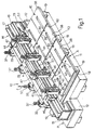
- number 10 indicates as a whole a machine tool for machining printed circuit boards 9 ( Figure 5), and which comprises a base 11 made, for example, of steel and in turn comprising two lateral appendixes 12 adjacent to the rear side P of machine 10.
- Appendixes 12 are fitted with two lateral uprights 13 in turn fitted with a steel crosspiece 14 comprising a strong horizontal plate 16 supporting two prismatic guides 15, and two strong vertical plates 17.
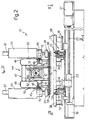
- Machine 10 also comprises a worktable 18 movable in a first direction hereinafter indicated as axis Y. More specifically, table 18 is guided by four longitudinal guides 19 fitted to base 11, and is moved along axis Y by a numerically controlled reversible electric motor 21 ( Figure 2) via a screw 22 engaging a nut screw 23 fitted to table 18.
- a numerically controlled reversible electric motor 21 Figure 2
- printed circuit boards 9 are normally rectangular with a short side or smaller dimension m and a long side or larger dimension M, and are machined - mainly drilled but also possibly milled - in packs 24, each comprising a number of boards 9, e.g. three, for machining simultaneously.
- boards 9 in each pack 24 are packed between an auxiliary bottom plate 26 and an auxiliary cover plate 27, and are connected, i.e. pinned, to one another by a pair of pins 28 and 29 located along the center line of pack 24, at two edges 31 and 32 parallel to short side m, and which project from auxiliary bottom plate 26 to define two locating pins by which to position the pack on table 18.
- boards 9 are positioned on table 18 ( Figures 1 and 2) with short side m parallel to axis Y. More specifically, machine 10 comprises two rows of machining heads 33, each row comprising four heads 33; table 18 is designed to receive two corresponding rows of four packs 24; and each machining head 33, in itself known, comprises a vertical tool spindle 34 for receiving a tool 36, and which is moved along a vertical axis Z by a numerically controlled reversible electric motor 37.
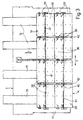
- Table 18 comprises two rows of known fixtures 38, each for aligning and locking a respective pack 24 for machining. More specifically, each fixture 38 ( Figure 3) comprises a rectangular plate with two short sides 39, and which is positioned with short sides 39 parallel to axis Y, and is screwed to table 18; a V-shaped seat 40 for receiving, for example, locating pin 28 of pack 24; and a groove 41 for receiving the other locating pin 29 of pack 24. As groove 41 receives pin 29 regardless of the distance between pins 29 and 28, each fixture 38 may therefore receive packs 24 differing in size within certain limits.
- the grooves 41 of fixtures 38 in each row are aligned along the X axis; the corresponding fixtures 38 in the two rows are so located as to minimize the distance between respective grooves 41; and the corresponding fixtures 38 in the two rows define pairs of fixtures 38, which are so spaced along the X axis as to leave gaps 42 between adjacent sides 39 ( Figure 4).
- the corresponding machining heads 33 in the two rows define pairs of heads 33, and are aligned along the Y axis; heads 33 in the two rows are so located that the distance between the axes of the two spindles 34 ( Figures 1 and 3) of each pair of heads 33 equals the distance between the axes of each pair of grooves 41; and heads 33 in each row are so located that the distance, along the X axis, between the axes of respective spindles 34 ( Figures 1 and 3) equals the distance between seats 40 of adjacent fixtures 38 in each row.
- Heads 33 are guided along the X axis by crosspiece 14. More specifically, heads 33 are supported on a common carriage 44 defined by two parallel bars 46 connected by a number of cross members 47; bars 46 are made of steel box section; and cross members 47 (Figure 2) comprise three horizontal plates 43 connected by transverse plates.
- Each box section bar 46 is reinforced by two prismatic bars 45 and 50 parallel to the X axis. More specifically, bars 45 and 50 are rectangular in section, and provide for securing heads 33 to carriage 44; each bar 45 comprises a number of shoes 48, each engaging two faces of the corresponding prismatic guide 15; and plate 16 supports a numerically controlled reversible electric motor 49 ( Figure 4) for moving carriage 44 along axis X via a screw 51 engaging a nut screw 52 fitted to a plate 43 of one of cross members 47 of carriage 44.
- the work travel of carriage 44 along axis X ( Figure 1) is 720 mm; the work travel of table 18 along axis Y is barely 570 mm; table 18 may be moved forward into the Figure 1 and 2 position to load and unload packs 24 from the front A of machine 10; and the total length of the machine may advantageously be kept within roughly 4000 mm, with a width of less than 2350 mm.
- table 18 is moved forward into the Figure 1 position allowing easy access by the operator not only to fixtures 38 in the front row, but also those in the rear row, the mid portion of which is roughly 800 mm from the front edge of table 18.
- the holes drilled into boards 9 are normally laid out, as is known, in rows and columns; and, on machine tool 10, the columns of hole locations are arranged parallel to the X axis.
- table 18 is first moved from the Figure 1 loading and unloading position to a work position in which, for example, the first column of hole locations of packs 24 in the rear row corresponds with tools 36 of machining heads 33 in the rear row, and the first column of hole locations of packs 24 in the front row corresponds with tools 36 of machining heads 33 in the front row.
- Carriage 44 is then moved to set the eight machining heads 33 over the corresponding hole locations of the eight packs 24, the eight heads 33 are operated either simultaneously or selectively, and so on for each hole location in each column.
- table 18 is moved each time along axis Y; and, once all the holes are drilled, table 18 is restored to the loading and unloading position shown in Figure 1.
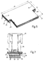
- the machining heads 33 in each pair are provided with a common store 54 for tools 36, which is fitted to a support in turn fitted to rectangular-section bars 45 of carriage 44 ( Figures 6 and 7). More specifically, for each pair of heads 33, rectangular-section bars 45 of carriage 44 are fitted with two pairs of brackets 56 (not shown in Figure 1 for the sake of simplicity) located respectively to the right and left of heads 33; each bracket 56 comprises pairs of V-section guide rollers 55; and the rollers 55 of two corresponding brackets of the two bars 45 may be fitted removably in between with a respective box 57 containing a number of tools 36 arranged in rows and columns.
- each box 57 comprises an inverted-L-section body 58 ( Figure 7) in turn comprising two wedge-shaped edges 59 engaging rollers 55; body 58 comprises a number of separating elements 61 defining a number of prismatic guides; and each prismatic guide is insertable with a clip comprising a plastic strip 62 supporting a row of fourteen, e.g. collarless, tools 36.
- each strip 62 comprises an asymmetric cavity engaging a washer 63 ( Figure 6) at the front (on the left in Figure 7) of element 61 to ensure foolproof insertion of strip 62; and the two ends of body 58 ( Figure 6) are provided with respective strengtheners 64, 66, each comprising a guard 67 for preventing the tips of tools 36 from contacting a supporting surface.
- Strengthener 66 of each box 57 comprises a grip 68, and a retaining element 69 which engages a known hand-operated release lever 71; and boxes 57 are easily inserted and removed from between rollers 55 of brackets 56 by the operator stationed at the front A of machine 10.
- Box 57 contains forty-two strips 62, making a total capacity of 588 tools 36.
- Store 54 of tools 36 of each pair of heads 33 may comprise only one box 57 of 588 tools, which may be located, for example, between the brackets to the right of heads 33, as in Figure 1. Or, if a greater number of tools 36 is required, store 54 may comprise two boxes 57 located between two pairs of brackets 56 of each pair of heads 33, making a total capacity of store 54 of 1176 tools.
- Table 18 ( Figures 2 and 3) comprises five pairs of tool-change devices 72, each comprising a pneumatically operated gripped 73, which provides for removing tool 36 both from spindle 34 and from store 54, and which is moved along the Z axis by a corresponding pneumatic piston 74.
- Three pairs of devices 72 are located in the three gaps 42 between adjacent pairs of fixtures 38; two pairs of devices 72 are located adjacent to the two outer edges 39 of the lateral pairs of fixtures 38; the devices 72 of all five pairs are arranged in two rows corresponding with the two rows of machining heads 33; and the grippers 73 of each pair of devices 72 are separated by a distance equal to that between the axes of a pair of spindles 34.
- the tools 36 in boxes 57 fitted to brackets 56 to the right of pairs of heads 33 are changed by the three pairs of devices 72 in gaps 42 and the pair of devices 72 adjacent to the outer side 39 of lateral fixtures 38 on the right; and the tools 36 in boxes 57 fitted to brackets 56 to the left of pairs of heads 33 are changed by the three pairs of devices 72 in gaps 42 and the pair adjacent to the outer side 39 of lateral fixtures 38 on the left.
- Tools 36 of all eight machining heads 33 are changed simultaneously. Firstly, table 18 is moved along the Y axis into a tool-change position in which grippers 73 are positioned in the two transverse planes containing the axes of spindles 34; and, at the same time, carriage 44 is moved along the X axis into a tool-change position in which the axes of spindles 34 correspond with respective grippers 73.
- grippers 73 are raised simultaneously by pistons 74 to engage tools 36 of respective spindles 34; as grippers 73 are closed, spindles 34 are opened, and grippers 73 are lowered to withdraw the eight worn tools 36 from spindles 34; and carriage 44 is moved along the X axis to bring the rows of boxes 57 in which to deposit the worn tools 36 withdrawn from the rear row of spindles 34 into the planes containing the axes of pairs of grippers 73.
- table 18 is moved along the Y axis to align the rear row of grippers 73 with the strips 62 into which the worn tools 36 are to be deposited by grippers 73; pistons 74 of the rear row of grippers 73 are activated to insert the worn tools 36 inside the respective seats in strips 62; and carriage 44 and table 18 are again operated to insert the worn tools 36 of the front row of grippers 73 inside the respective seats.
- carriage 44 and table 18 are again operated, a first time to withdraw, by means of the rear row of grippers 73, the new tools 36 to be inserted inside the rear row of spindles 34, and a second time to withdraw, by means of the front row of grippers 73, the new tools 36 to be inserted inside the front row of spindles 34.
- carriage 44 and table 18 are again operated to align the eight grippers 73 with the eight spindles 34, so that the eight new tools 36 are inserted simultaneously inside spindles 34.
- the machine is lightweight, compact and cheap to produce; the short length of crosspiece 14 provides for a high degree of machining precision; and the narrow width of the machine enables packs 24 of boards 9 as well as boxes 57 of tools 36 to be loaded and unloaded from front side A, thus reducing the amount of floor space required.
- using a common tool store 54 for each pair of machining heads 33 provides for simplifying the structure of the machine; and using two boxes 57 of tools 36 for each pair of heads 33 provides for doubling the number of tools 36 available by simply providing a pair of tool-change devices 72.
- each box 57 of tools 36 may be inserted in a prismatic guide as opposed to between rollers 55.
- tool store 54 may be in the form of a drum, which may be rotated selectively to select a given tool location; and the sequence of tool-change operations may be varied, so that the new tools 36 are withdrawn from store 54 by each row of devices 72 as soon as the respective worn tools 36 are inserted.
Landscapes
- Engineering & Computer Science (AREA)
- Mechanical Engineering (AREA)
- Manufacturing & Machinery (AREA)
- Microelectronics & Electronic Packaging (AREA)
- Automatic Tool Replacement In Machine Tools (AREA)
- Drilling And Boring (AREA)
- Machine Tool Units (AREA)
- Perforating, Stamping-Out Or Severing By Means Other Than Cutting (AREA)
Applications Claiming Priority (2)
| Application Number | Priority Date | Filing Date | Title |
|---|---|---|---|
| ITTO970869 | 1997-10-02 | ||
| IT97TO000869A IT1295457B1 (it) | 1997-10-02 | 1997-10-02 | Macchina utensile avente una serie di teste operatrici per la lavorazione di piastre di circuiti stampati. |
Publications (3)
| Publication Number | Publication Date |
|---|---|
| EP0906806A2 true EP0906806A2 (de) | 1999-04-07 |
| EP0906806A3 EP0906806A3 (de) | 2000-03-29 |
| EP0906806B1 EP0906806B1 (de) | 2003-08-27 |
Family
ID=11416039
Family Applications (1)
| Application Number | Title | Priority Date | Filing Date |
|---|---|---|---|
| EP98118599A Expired - Lifetime EP0906806B1 (de) | 1997-10-02 | 1998-10-01 | Werkzeugmaschine mit mehreren Bearbeitungsköpfen für die Bearbeitung von Leiterplatten |
Country Status (6)
| Country | Link |
|---|---|
| US (1) | US6098274A (de) |
| EP (1) | EP0906806B1 (de) |
| JP (1) | JPH11240000A (de) |
| DE (1) | DE69817492T2 (de) |
| IT (1) | IT1295457B1 (de) |
| TW (1) | TW442355B (de) |
Cited By (3)
| Publication number | Priority date | Publication date | Assignee | Title |
|---|---|---|---|---|
| DE10221532A1 (de) * | 2002-05-15 | 2003-11-27 | Schmoll Gmbh Maschinen | Automatisierte Werkzeugmaschine |
| EP3511123A1 (de) * | 2018-01-11 | 2019-07-17 | Paolino Bacci S.R.L. | Bearbeitungszentrum mit zwei tischen |
| IT202000021970A1 (it) * | 2020-09-17 | 2022-03-17 | Pade S R L | Centro di lavoro |
Families Citing this family (14)
| Publication number | Priority date | Publication date | Assignee | Title |
|---|---|---|---|---|
| KR100311747B1 (ko) * | 1999-08-20 | 2001-10-18 | 정문술 | 표면실장기의 인쇄회로기판 이송장치 |
| JP4367863B2 (ja) * | 2007-03-28 | 2009-11-18 | 日立ビアメカニクス株式会社 | プリント基板加工機 |
| US20100243617A1 (en) * | 2009-03-26 | 2010-09-30 | Electro Scientific Industries, Inc. | Printed circuit board via drilling stage assembly |
| KR101078011B1 (ko) | 2009-04-24 | 2011-10-31 | 주식회사 져스텍 | 이송 유니트 및 이를 구비하는 이송 장치 |
| CN101947659B (zh) * | 2010-08-31 | 2012-10-10 | 广州杰赛科技股份有限公司 | 一种钻机横向跨轴进行钻孔加工的方法 |
| US9751174B2 (en) * | 2012-06-07 | 2017-09-05 | C. R. Onsrud, Inc. | Multiple tool changer for machining center |
| JP2015193069A (ja) * | 2014-03-27 | 2015-11-05 | 三星ダイヤモンド工業株式会社 | 加工ヘッド及び溝加工装置 |
| US9504163B2 (en) * | 2014-08-28 | 2016-11-22 | Wojciech B. Kosmowski | Y axis beam positioning system for a PCB drilling machine |
| DE102014219060A1 (de) * | 2014-09-22 | 2016-03-24 | Homag Holzbearbeitungssysteme Gmbh | Bearbeitungsvorrichtung |
| IT201600074396A1 (it) * | 2016-07-15 | 2018-01-15 | Paolino Bacci Srl | Centro di lavoro |
| JP6227184B1 (ja) * | 2017-07-04 | 2017-11-08 | 明 杉山 | フレキシブル複数テーブル装置 |
| CN112170893A (zh) * | 2020-09-25 | 2021-01-05 | 肖金坚 | 一种洗地车刮板加工用具有定位结构的高效率穿孔装置 |
| CN116460335B (zh) * | 2023-05-16 | 2023-12-29 | 广东华途仕建材实业有限公司 | 一种用于金属板钻孔设备 |
| CN117564666B (zh) * | 2023-12-28 | 2026-02-27 | 大连奥托自动化设备有限公司 | 一种自动上料式双面压装装置 |
Family Cites Families (16)
| Publication number | Priority date | Publication date | Assignee | Title |
|---|---|---|---|---|
| US1060705A (en) * | 1912-06-15 | 1913-05-06 | James Charles Potter | Milling-machine. |
| US3583054A (en) * | 1968-12-05 | 1971-06-08 | Richard G Hughes | Stack drilling and pinning machine |
| DE2535973A1 (de) * | 1975-08-12 | 1977-02-17 | Siemens Ag | Mehrspindelbohrautomat, insbesondere zum bohren von leiterplatten |
| IT1165542B (it) * | 1983-02-17 | 1987-04-22 | Prt Pluritec Italia Spa | Foratrice per piastre particolarmente di supporto di circuiti stampati |
| JPS60207746A (ja) * | 1984-03-30 | 1985-10-19 | Washino Koki Kk | 多面加工機械 |
| US4765784A (en) * | 1984-12-06 | 1988-08-23 | Advanced Controls, Inc. | Electronic depth control for drill |
| US4715108A (en) * | 1985-03-07 | 1987-12-29 | Toshiba Kikai Kabushiki Kaisha | Machine tool capable of changing worn cutting tools, such as small diameter drills, with new ones |
| JPS62259707A (ja) * | 1986-05-06 | 1987-11-12 | Hiraoka Kogyo Kk | プリント配線板用穿孔機 |
| JPH088433B2 (ja) * | 1987-01-20 | 1996-01-29 | ヤマハ発動機株式会社 | チツプ部品装着装置 |
| DE3719167C1 (de) * | 1987-06-09 | 1988-11-03 | Klingelnberg Soehne | Numerisch gesteuerte Leiterplatten-Bearbeitungsmaschine |
| US4982831A (en) * | 1989-02-28 | 1991-01-08 | Hitachi Seiko, Ltd. | Printed circuit board adapter supplying apparatus and method for use in printed circuit board drilling apparatus |
| US5109584A (en) * | 1989-02-28 | 1992-05-05 | Hitachi Seiko Ltd. | Printed circuit board adapter supplying apparatus and method for use in printed circuit board drilling apparatus |
| US5075530A (en) * | 1990-07-23 | 1991-12-24 | Lee Shih Lu | Multi-head type of electro-discharging machine |
| FR2667478B1 (fr) * | 1990-09-28 | 1996-01-12 | Posalux Sa | Machine-outil, notamment pour l'usinage de plaques de circuits imprimes. |
| DE4228062C1 (de) * | 1992-08-24 | 1994-04-28 | Alfred Ullrich Berger | Vorrichtung zum Herstellen von Bohrlöchern, vorzugsweise in plattenförmigen Werkstücken |
| JP3402876B2 (ja) * | 1995-10-04 | 2003-05-06 | ヤマハ発動機株式会社 | 表面実装機 |
-
1997
- 1997-10-02 IT IT97TO000869A patent/IT1295457B1/it active IP Right Grant
- 1997-10-17 TW TW086115307A patent/TW442355B/zh not_active IP Right Cessation
-
1998
- 1998-09-29 US US09/163,069 patent/US6098274A/en not_active Expired - Fee Related
- 1998-10-01 DE DE69817492T patent/DE69817492T2/de not_active Expired - Fee Related
- 1998-10-01 EP EP98118599A patent/EP0906806B1/de not_active Expired - Lifetime
- 1998-10-02 JP JP10281762A patent/JPH11240000A/ja active Pending
Cited By (4)
| Publication number | Priority date | Publication date | Assignee | Title |
|---|---|---|---|---|
| DE10221532A1 (de) * | 2002-05-15 | 2003-11-27 | Schmoll Gmbh Maschinen | Automatisierte Werkzeugmaschine |
| DE10221532B4 (de) * | 2002-05-15 | 2005-09-22 | Schmoll Maschinen Gmbh | Automatisierte Werkzeugmaschine |
| EP3511123A1 (de) * | 2018-01-11 | 2019-07-17 | Paolino Bacci S.R.L. | Bearbeitungszentrum mit zwei tischen |
| IT202000021970A1 (it) * | 2020-09-17 | 2022-03-17 | Pade S R L | Centro di lavoro |
Also Published As
| Publication number | Publication date |
|---|---|
| EP0906806A3 (de) | 2000-03-29 |
| JPH11240000A (ja) | 1999-09-07 |
| ITTO970869A1 (it) | 1999-04-02 |
| DE69817492D1 (de) | 2003-10-02 |
| TW442355B (en) | 2001-06-23 |
| US6098274A (en) | 2000-08-08 |
| IT1295457B1 (it) | 1999-05-12 |
| DE69817492T2 (de) | 2004-06-17 |
| EP0906806B1 (de) | 2003-08-27 |
Similar Documents
| Publication | Publication Date | Title |
|---|---|---|
| US6098274A (en) | Machine tool featuring a number of machining heads for machining printed circuit boards | |
| KR100371763B1 (ko) | 머쉬이닝센터 | |
| US6013017A (en) | Punch press machine | |
| US6183190B1 (en) | Method of stacking packs of printed circuit boards and relative pack loading and unloading device for a machine tool | |
| JP5005046B2 (ja) | 工具マガジン | |
| HU220906B1 (en) | Machine tool with horizontal spindles | |
| DE10119175A1 (de) | Vorrichtung zur Bearbeitung von Werkstücken sowie Verfahren zur Bearbeitung von Werkstücken unter Verwendung einer solchen Vorrichtung | |
| CN102056710A (zh) | 用于机床的托盘操纵系统 | |
| EP0138600B1 (de) | Werkzeugbereitstellungssystem für eine Werkzeugmaschine | |
| EP0891126B1 (de) | Bohreinheit für Leiterplatte mit zwei individuell bewegbaren Antriebsköpfen | |
| ITTO930832A1 (it) | Macchina operatrice per la lavorazione meccanica di piastre, in particolare per circuiti stampati. | |
| EP2527080B1 (de) | Bearbeitungszentrum mit Stütz- und Bewegungssystem | |
| EP0483781A2 (de) | Werkzeugmagazin | |
| EP1287947A1 (de) | Handhabungsvorrichtung | |
| DE3022717A1 (de) | Werkzeugmaschine mit einer automatischen werkzeugwechselvorrichtung | |
| JP2002096122A (ja) | パンチプレス | |
| EP1169158A1 (de) | Verfahren und vorrichtung zum bearbeiten von werkstücken | |
| DE3431349A1 (de) | Einrichtung an nc-bearbeitungsmaschinen zum zu- und abfuehren von werkstuecken | |
| DE19747995C2 (de) | Selbstladendes Bearbeitungszentrum mit Werkstück- und Werkzeugmagazinen | |
| DE102008017719B4 (de) | Bearbeitungsanlage zum Bearbeiten von Werkstücken | |
| US6371898B1 (en) | Tool-change system for a machine tool with a number of machining heads | |
| JPH115132A (ja) | パンチプレス機 | |
| EP1755823B1 (de) | Vorrichtung zum speichern und handhaben von werkzeugen eines bearbeitungszentrums | |
| DE102024131388A1 (de) | Bearbeitungsvorrichtung sowie Verfahren | |
| US5711641A (en) | Method and device for loading and unloading printed circuit boards on a machine tool |
Legal Events
| Date | Code | Title | Description |
|---|---|---|---|
| PUAI | Public reference made under article 153(3) epc to a published international application that has entered the european phase |
Free format text: ORIGINAL CODE: 0009012 |
|
| AK | Designated contracting states |
Kind code of ref document: A2 Designated state(s): BE CH DE FR GB LI |
|
| AX | Request for extension of the european patent |
Free format text: AL;LT;LV;MK;RO;SI |
|
| PUAL | Search report despatched |
Free format text: ORIGINAL CODE: 0009013 |
|
| AK | Designated contracting states |
Kind code of ref document: A3 Designated state(s): AT BE CH CY DE DK ES FI FR GB GR IE IT LI LU MC NL PT SE |
|
| AX | Request for extension of the european patent |
Free format text: AL;LT;LV;MK;RO;SI |
|
| 17P | Request for examination filed |
Effective date: 20000807 |
|
| AKX | Designation fees paid |
Free format text: BE CH DE FR GB LI |
|
| 17Q | First examination report despatched |
Effective date: 20020415 |
|
| RAP1 | Party data changed (applicant data changed or rights of an application transferred) |
Owner name: ACD TECHNOLOGIES S.P.A |
|
| GRAH | Despatch of communication of intention to grant a patent |
Free format text: ORIGINAL CODE: EPIDOS IGRA |
|
| GRAS | Grant fee paid |
Free format text: ORIGINAL CODE: EPIDOSNIGR3 |
|
| GRAA | (expected) grant |
Free format text: ORIGINAL CODE: 0009210 |
|
| AK | Designated contracting states |
Designated state(s): BE CH DE FR GB LI |
|
| PG25 | Lapsed in a contracting state [announced via postgrant information from national office to epo] |
Ref country code: FR Free format text: LAPSE BECAUSE OF FAILURE TO SUBMIT A TRANSLATION OF THE DESCRIPTION OR TO PAY THE FEE WITHIN THE PRESCRIBED TIME-LIMIT Effective date: 20030827 Ref country code: BE Free format text: LAPSE BECAUSE OF FAILURE TO SUBMIT A TRANSLATION OF THE DESCRIPTION OR TO PAY THE FEE WITHIN THE PRESCRIBED TIME-LIMIT Effective date: 20030827 |
|
| REG | Reference to a national code |
Ref country code: GB Ref legal event code: FG4D |
|
| REG | Reference to a national code |
Ref country code: CH Ref legal event code: NV Representative=s name: N&G PATENT SERVICES SA Ref country code: CH Ref legal event code: EP |
|
| REF | Corresponds to: |
Ref document number: 69817492 Country of ref document: DE Date of ref document: 20031002 Kind code of ref document: P |
|
| PG25 | Lapsed in a contracting state [announced via postgrant information from national office to epo] |
Ref country code: GB Free format text: LAPSE BECAUSE OF NON-PAYMENT OF DUE FEES Effective date: 20031127 |
|
| PLBE | No opposition filed within time limit |
Free format text: ORIGINAL CODE: 0009261 |
|
| STAA | Information on the status of an ep patent application or granted ep patent |
Free format text: STATUS: NO OPPOSITION FILED WITHIN TIME LIMIT |
|
| GBPC | Gb: european patent ceased through non-payment of renewal fee |
Effective date: 20031127 |
|
| 26N | No opposition filed |
Effective date: 20040528 |
|
| EN | Fr: translation not filed | ||
| PGFP | Annual fee paid to national office [announced via postgrant information from national office to epo] |
Ref country code: CH Payment date: 20051028 Year of fee payment: 8 |
|
| PGFP | Annual fee paid to national office [announced via postgrant information from national office to epo] |
Ref country code: DE Payment date: 20051215 Year of fee payment: 8 |
|
| PG25 | Lapsed in a contracting state [announced via postgrant information from national office to epo] |
Ref country code: LI Free format text: LAPSE BECAUSE OF NON-PAYMENT OF DUE FEES Effective date: 20061031 Ref country code: CH Free format text: LAPSE BECAUSE OF NON-PAYMENT OF DUE FEES Effective date: 20061031 |
|
| PG25 | Lapsed in a contracting state [announced via postgrant information from national office to epo] |
Ref country code: DE Free format text: LAPSE BECAUSE OF NON-PAYMENT OF DUE FEES Effective date: 20070501 |
|
| REG | Reference to a national code |
Ref country code: CH Ref legal event code: PL |