EP0906808A2 - Verfahren zum Stapeln von Packen von Leiterplatten und entsprechende Vorrichtung zum Laden und Entladen von Packen für eine Werkzeugmaschine - Google Patents
Verfahren zum Stapeln von Packen von Leiterplatten und entsprechende Vorrichtung zum Laden und Entladen von Packen für eine Werkzeugmaschine Download PDFInfo
- Publication number
- EP0906808A2 EP0906808A2 EP98118304A EP98118304A EP0906808A2 EP 0906808 A2 EP0906808 A2 EP 0906808A2 EP 98118304 A EP98118304 A EP 98118304A EP 98118304 A EP98118304 A EP 98118304A EP 0906808 A2 EP0906808 A2 EP 0906808A2
- Authority
- EP
- European Patent Office
- Prior art keywords
- pack
- packs
- pins
- holes
- worktable
- Prior art date
- Legal status (The legal status is an assumption and is not a legal conclusion. Google has not performed a legal analysis and makes no representation as to the accuracy of the status listed.)
- Withdrawn
Links
- 238000000034 method Methods 0.000 title claims description 16
- 238000003754 machining Methods 0.000 claims abstract description 40
- 230000007246 mechanism Effects 0.000 claims abstract description 20
- 230000000712 assembly Effects 0.000 claims description 14
- 238000000429 assembly Methods 0.000 claims description 14
- 230000002441 reversible effect Effects 0.000 claims description 5
- 230000003287 optical effect Effects 0.000 claims description 3
- 238000006073 displacement reaction Methods 0.000 claims description 2
- 229910000831 Steel Inorganic materials 0.000 description 1
- 230000006835 compression Effects 0.000 description 1
- 238000007906 compression Methods 0.000 description 1
- 238000005553 drilling Methods 0.000 description 1
- 238000003801 milling Methods 0.000 description 1
- 229940070225 rest simply Drugs 0.000 description 1
- 239000010959 steel Substances 0.000 description 1
Images



Classifications
-
- B—PERFORMING OPERATIONS; TRANSPORTING
- B23—MACHINE TOOLS; METAL-WORKING NOT OTHERWISE PROVIDED FOR
- B23Q—DETAILS, COMPONENTS, OR ACCESSORIES FOR MACHINE TOOLS, e.g. ARRANGEMENTS FOR COPYING OR CONTROLLING; MACHINE TOOLS IN GENERAL CHARACTERISED BY THE CONSTRUCTION OF PARTICULAR DETAILS OR COMPONENTS; COMBINATIONS OR ASSOCIATIONS OF METAL-WORKING MACHINES, NOT DIRECTED TO A PARTICULAR RESULT
- B23Q7/00—Arrangements for handling work specially combined with or arranged in, or specially adapted for use in connection with, machine tools, e.g. for conveying, loading, positioning, discharging, sorting
-
- H—ELECTRICITY
- H05—ELECTRIC TECHNIQUES NOT OTHERWISE PROVIDED FOR
- H05K—PRINTED CIRCUITS; CASINGS OR CONSTRUCTIONAL DETAILS OF ELECTRIC APPARATUS; MANUFACTURE OF ASSEMBLAGES OF ELECTRICAL COMPONENTS
- H05K13/00—Apparatus or processes specially adapted for manufacturing or adjusting assemblages of electric components
- H05K13/0061—Tools for holding the circuit boards during processing; handling transport of printed circuit boards
-
- H—ELECTRICITY
- H05—ELECTRIC TECHNIQUES NOT OTHERWISE PROVIDED FOR
- H05K—PRINTED CIRCUITS; CASINGS OR CONSTRUCTIONAL DETAILS OF ELECTRIC APPARATUS; MANUFACTURE OF ASSEMBLAGES OF ELECTRICAL COMPONENTS
- H05K3/00—Apparatus or processes for manufacturing printed circuits
- H05K3/0097—Processing two or more printed circuits simultaneously, e.g. made from a common substrate, or temporarily stacked circuit boards
-
- H—ELECTRICITY
- H05—ELECTRIC TECHNIQUES NOT OTHERWISE PROVIDED FOR
- H05K—PRINTED CIRCUITS; CASINGS OR CONSTRUCTIONAL DETAILS OF ELECTRIC APPARATUS; MANUFACTURE OF ASSEMBLAGES OF ELECTRICAL COMPONENTS
- H05K2203/00—Indexing scheme relating to apparatus or processes for manufacturing printed circuits covered by H05K3/00
- H05K2203/15—Position of the PCB during processing
- H05K2203/1536—Temporarily stacked PCBs
-
- H—ELECTRICITY
- H05—ELECTRIC TECHNIQUES NOT OTHERWISE PROVIDED FOR
- H05K—PRINTED CIRCUITS; CASINGS OR CONSTRUCTIONAL DETAILS OF ELECTRIC APPARATUS; MANUFACTURE OF ASSEMBLAGES OF ELECTRICAL COMPONENTS
- H05K2203/00—Indexing scheme relating to apparatus or processes for manufacturing printed circuits covered by H05K3/00
- H05K2203/16—Inspection; Monitoring; Aligning
- H05K2203/167—Using mechanical means for positioning, alignment or registration, e.g. using rod-in-hole alignment
-
- H—ELECTRICITY
- H05—ELECTRIC TECHNIQUES NOT OTHERWISE PROVIDED FOR
- H05K—PRINTED CIRCUITS; CASINGS OR CONSTRUCTIONAL DETAILS OF ELECTRIC APPARATUS; MANUFACTURE OF ASSEMBLAGES OF ELECTRICAL COMPONENTS
- H05K3/00—Apparatus or processes for manufacturing printed circuits
- H05K3/0008—Apparatus or processes for manufacturing printed circuits for aligning or positioning of tools relative to the circuit board
-
- H—ELECTRICITY
- H05—ELECTRIC TECHNIQUES NOT OTHERWISE PROVIDED FOR
- H05K—PRINTED CIRCUITS; CASINGS OR CONSTRUCTIONAL DETAILS OF ELECTRIC APPARATUS; MANUFACTURE OF ASSEMBLAGES OF ELECTRICAL COMPONENTS
- H05K3/00—Apparatus or processes for manufacturing printed circuits
- H05K3/0011—Working of insulating substrates or insulating layers
- H05K3/0044—Mechanical working of the substrate, e.g. drilling or punching
- H05K3/0047—Drilling of holes
-
- H—ELECTRICITY
- H05—ELECTRIC TECHNIQUES NOT OTHERWISE PROVIDED FOR
- H05K—PRINTED CIRCUITS; CASINGS OR CONSTRUCTIONAL DETAILS OF ELECTRIC APPARATUS; MANUFACTURE OF ASSEMBLAGES OF ELECTRICAL COMPONENTS
- H05K3/00—Apparatus or processes for manufacturing printed circuits
- H05K3/0011—Working of insulating substrates or insulating layers
- H05K3/0044—Mechanical working of the substrate, e.g. drilling or punching
- H05K3/0052—Depaneling, i.e. dividing a panel into circuit boards; Working of the edges of circuit boards
-
- Y—GENERAL TAGGING OF NEW TECHNOLOGICAL DEVELOPMENTS; GENERAL TAGGING OF CROSS-SECTIONAL TECHNOLOGIES SPANNING OVER SEVERAL SECTIONS OF THE IPC; TECHNICAL SUBJECTS COVERED BY FORMER USPC CROSS-REFERENCE ART COLLECTIONS [XRACs] AND DIGESTS
- Y10—TECHNICAL SUBJECTS COVERED BY FORMER USPC
- Y10S—TECHNICAL SUBJECTS COVERED BY FORMER USPC CROSS-REFERENCE ART COLLECTIONS [XRACs] AND DIGESTS
- Y10S269/00—Work holders
- Y10S269/903—Work holder for electrical circuit assemblages or wiring systems
Definitions
- the present invention relates to a method of stacking packs of printed circuit boards; to a pack loading and unloading device and pack unpinning mechanism for a machine tool; and to a pack of printed circuit boards stackable using the method according to the invention.
- packs of printed circuit boards are normally provided with two locating pins along the center line and adjacent to two opposite edges of the pack, which pins project from one face of the pack and are essential for aligning and securing the pack to the table of the machine tool.
- the pins prevent the packs from being stacked contacting one another, e.g. for storage, and, to prevent the pins of one pack from damaging the adjacent pack, the packs must be separated by a distance greater than the length of the pins. For this reason, the packs are normally stacked in special trays for protecting the pins and maintaining the necessary distance between the packs. Such trays, however, take up an enormous amount of space, thus increasing the storage cost of the packs.
- One known machine with a number of machining heads comprises an automatic pack loading and unloading device, wherein two mechanisms are provided on either side of the machine for vertically moving two racks, one for loading and the other for unloading packs of printed circuit boards.
- the packs are moved along the X axis on two guides parallel to the X axis, and which are movable vertically to keep the pins detached from the table during transport; and the packs are then fed in steps to the various machining heads.
- the loading and unloading device is extremely complicated, expensive and slow-operating.
- Another known machine provides for feeding the machining head by means of a rack having a number of pack supporting trays.
- the rack is located at the rear of the machine, and the pack is pushed along the Y axis of the tray onto a pack aligning and clamping fixture having a groove for housing the pins.
- the device At each loading and unloading cycle, the device must transfer the machined pack back onto the original tray and remove another pack from the next tray. Moreover, in the case of a number of machining heads, an equal number of racks are required, which means this device, too, is fairly complicated and expensive.
- each pack comprises a pair of opposite edges, and a pair of locating elements located along the center line of the pack and adjacent to said edges; characterized by providing each pack with at least one pair of holes separated by a distance equal to that between said locating elements; and by placing a further pack on each pack so as to insert the locating elements of said further pack inside the holes of the underlying pack.
- the device for loading and unloading packs of printed circuit boards on and off a table of a machine tool comprises a loading station for loading the packs to be machined, and an unloading station for unloading the machined packs; said table comprising at least one aligning and clamping fixture acting on said pair of locating elements to align and clamp a pack of printed circuit boards during machining; and the device being characterized in that a transfer device for transferring said packs is movable between said fixture and at least one of said stations.
- Number 1 in Figure 1 indicates as a whole a pack of printed circuit boards 2 as arranged for machining, which normally comprises drilling and milling.
- Boards 2 are substantially rectangular with a short side or smaller dimension m and a long side or larger dimension M; and pack 1 also comprises an auxiliary bottom board 3 and an auxiliary cover board 4.
- Boards 2-4 are connected to one another by a pair of locating elements defined by a pair of cylindrical pins 5 and 6, which are located along the center line A (Figure 2) of pack 1, adjacent to two edges 7 parallel to short side m, and project downwards by a given length L from auxiliary bottom board 3.
- Pack 1 is of a thickness S depending on the number and thickness of boards 2.
- pack 1 comprises at least one pair of holes 8 and 9 associated with pins 5 and 6 and separated by a distance equal to that between pins 5 and 6. More specifically, on each of the two sides defined by center line A, pack 1 comprises a number of pairs of holes 8 and 9 corresponding to length L of pins 5 and 6 and to thickness S of pack 1.
- Holes 8 and 9 are aligned with respective pins 5 and 6 along two lines parallel to edges 7, and, along each line, are equally spaced with respect to one another and with respect to respective pin 5, 6, so that packs 1 may be stacked in offset manner, with pins 5 and 6 housed inside holes 8, 9 of one or more underlying packs 1.
- pack 1 advantageously comprises two pairs of holes 8, 9 on each of the sides defined by center line A, as shown in Figures 1 and 2.
- the method of stacking packs 1 substantially comprises the step of providing the packs with holes 8 and 9; and the step of placing on each pack 1 a further pack 1, with the pins 5 and 6 of the further pack inserted inside holes 8 and 9 of the underlying pack.
- Packs 1 as shown in Figures 1 and 2 may be stacked, for example, on a storage shelf 20 ( Figure 3), by placing a first bottom pack 1 in position I with pins 5 and 6 inside a groove 25 on shelf 20; a second pack 1 is then placed in position II on top of first pack 1, with pins 5 and 6 inserted inside the pair of holes 8 and 9 adjacent to and to the right of (below, in Figure 2) pins 5 and 6 of first pack 1.
- the portion of pins 5 and 6 of second pack 1 possibly projecting downwards from first pack 1 are also housed inside groove 25.
- the two lower packs 1 have two pairs of coaxial holes 8 and 9 to receive the next pack 1, which is placed in position III on the second pack 1, with pins 5 and 6 inserted inside the coaxial holes 8 and 9 of the two underlying packs 1.
- Further packs 1 may thus be stacked cyclically in positions I-III as described above, and, though obviously stacked in offset manner, packs 1 are stacked contacting one another to reduce the amount of space required.
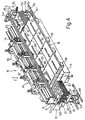
- Number 10 in Figure 4 indicates as a whole a machine tool for machining packs 1, and which comprises a bed 11 having two lateral appendixes 12 (only one shown in Figure 4) located adjacent to the rear side P of machine 10; appendixes 12 are fitted with two lateral uprights 13, in turn, fitted with a steel crosspiece 14; and machine 10 also comprises a worktable 18, which is moved along a number of guides 19, in a direction hereinafter referred to as the Y axis, by a known numeric-control electric motor (not shown).
- machine tool 10 comprises two rows of machining heads 33, each row defined by four heads 33; each head 33 comprises a vertical-axis tool-holder spindle 34 for receiving a tool 36, and which is moved along a vertical axis Z by a respective numeric-control reversible electric motor 37; and table 18 comprises two rows of known fixtures 38, each for aligning and clamping a pack 1 during machining, and each comprising a rectangular plate with two short sides 39 parallel to the Y axis.
- Each fixture 38 comprises a seat 40 for receiving, for example, locating pin 5 of pack 1; and a groove 41 for receiving the other locating pin 6 of pack 1.
- the grooves 41 in each row of fixtures 38 are aligned parallel to crosspiece 14, in a direction perpendicular to the Y axis and hereinafter referred to as the X axis; the fixtures 38 in the two rows are arranged adjacent one another to minimize the distance between respective grooves 41; machining heads 33 are carried by a common carriage 44 and so spaced as to correspond with fixtures 38; and carriage 44 is moved along the X axis by a known numeric-control electric motor (not shown).
- Machine 10 comprises a device, indicated as a whole by 46, for loading and unloading packs 1, and which comprises a loading station 47 for loading packs 1 for machining onto table 18, and an unloading station 48 for unloading the machined packs 1 off table 18.
- Stations 47 and 48 are located on either side of machine 10, substantially in front of the two appendixes 12 of bed 11, and are secured to bed 11 in any known manner.
- each station 47, 48 comprises a supporting structure 49 supporting two columns 51 connected at the top by a crosspiece 52; a lift carriage 53 slides along columns 51, and is powered by a reversible electric motor 54 via a screw-nut screw pair 56; carriage 53 supports a platform 57 for supporting a stack of packs 1; and crosspiece 52 is fitted with an optical sensor 55, 55' on a level with the top surface of fixtures 38.
- the sensor 55 of loading station 47 detects the top pack 1 on platform 57 to start, stop and control the rotation direction of motor 54, and is so located as to direct a light beam at a given angle, e.g. of 22° 30', with respect to the X axis, for the purpose explained later on.
- At least platform 57 of loading station 47 comprises a number of, e.g. five, holes 58 ( Figure 5) equally spaced with the same spacing as holes 8, and for housing pin 5 of a pack 1; and five grooves 59 parallel to crosspiece 14 and for housing pin 6.
- platform 57 of unloading station 48 does not require holes 58 or grooves 59, but may nevertheless be the same as platform 57 of loading station 47.
- Device 46 also comprises a transfer device 61 ( Figure 4) for transferring packs 1, and which is carried by a slide 62 of a known linear actuator 63 defining a straight guide for slide 62.
- Actuator 63 comprises a toothed belt cooperating with two horizontal-axis pulleys, one of which is rotated selectively by an electric motor 64 carried by crosspiece 52 of loading station 47; and actuator 63 is fitted to both crosspieces 52, and provides for moving slide 62 parallel to crosspiece 14 of machine 10.
- Device 61 comprises a group of six suction cups 66 ( Figures 6 and 7), which are activated to pick up one pack 1 at a time, e.g. off platform 57 of loading station 47. More specifically, suction cups 66 are arranged in two rows of three suction cups 66 each, and are moved telescopically in a given sequence to assist removal and enable gradual placement of pack 1 off and onto the respective support.
- Device 61 also comprises an activatable member for pushing one of packs 1 during transfer; which member is defined by a blade 67 hinged to a shaft 68 parallel to the Y axis, and which is rotated by an actuator (not shown) between a horizontal rest position ( Figure 4 and as indicated by the dash line in Figure 6) and a vertical position ( Figure 6) in which blade 67 engages an edge 7 of a pack 1 (Figure 12) to push the pack towards unloading station 48.
- an activatable member for pushing one of packs 1 during transfer; which member is defined by a blade 67 hinged to a shaft 68 parallel to the Y axis, and which is rotated by an actuator (not shown) between a horizontal rest position (Figure 4 and as indicated by the dash line in Figure 6) and a vertical position ( Figure 6) in which blade 67 engages an edge 7 of a pack 1 ( Figure 12) to push the pack towards unloading station 48.
- each machining head 33 ( Figure 11) comprises a mechanism 69 for unpinning the machined pack 1.
- Mechanism 69 comprises a punch 71 ( Figure 8) movable parallel to the axis of spindle 34 to remove, each time, a pin 5, 6 from pack 1; punch 71 is activated by a high-speed linear actuator comprising a pneumatic cylinder 72 fitted to head 33; and, at each fixture 38, table 18 comprises a bin (not shown) for collecting the removed pins 5, 6.
- Device 46 for loading and unloading packs 1 operates as follows.
- the operator To drill a number of packs 1 of printed circuit boards, for example, the operator first removes eight packs 1 off shelf 20 ( Figure 3) and stacks them one at a time by hand on platform 57 of loading station 47 ( Figure 4) set to the raised position. More specifically, the operator first places a first pack 1 on platform 57 ( Figure 5) with pin 5 inside the central hole 58, and pin 6 inside the central groove 59; sensor 55 activates motor 54 of station 47 to lower platform 57 by an amount equal to the thickness of the loaded pack 1; the operator then places a second pack 1 on the first pack 1, with pins 5 and 6 inserted inside holes 8 and 9; and so on, following the method described with reference to Figure 3.
- the control unit For each pack 1 to be loaded onto the rear row of fixtures 38 ( Figure 9), the control unit operates linear actuator 63 to position cursor 62 over station 47, and then lowers suction cups 66, as described previously, to engage the top pack 1. Suction cups 66 are then raised, and actuator 63 moves cursor 62 to position pack 1 over the required fixture 38. At the same time, the control unit also moves table 18 along the Y axis to align seat 40 and groove 41 of the required fixture 38 with pins 5 and 6 of pack 1.
- Sensor 55 detects the passage of pin 5, the delay of which indicates the location, along the Y axis, of pack 1 in the stack.
- the control unit determines the position in which to arrest table 18 to ensure pack 1 correctly engages fixture 38, regardless of the transverse position of the pack in the stack at loading station 47.
- control unit lowers suction cups 66 and cuts of suction to the cups to deposit pack 1 accurately onto fixture 38.
- the control unit moves table IS by an amount equal to the distance between the two rows of grooves 41, and the pack 1 loading cycles are repeated as for the rear row.
- Machining of the packs is normally programmed so that boards 2 in each pack 1 contain a number of printed circuits, e.g. nine, as shown in Figures 11 and 12; and, after machining, the control unit operates unpinning mechanisms 69 ( Figure 11) to unpin the machined packs 1.
- table 18 is first moved to position pins 5 and 6 of the rear row of packs 1 in the plane, parallel to crosspiece 14, containing punches 71; at the same time, carriage 44 is moved along the X axis to align punches 71 with pins 5 of packs 1; and the control unit then operates cylinders 72 ( Figure 8) and hence punches 71 to remove the four pins 5 from the rear row of packs 1.
- Carriage 44 is then moved rightwards by a distance equal to the distance between pins 5 and 6 of the packs, and cylinders 72 are again operated to remove pins 6 from the packs in the rear row.
- Table 18 is then moved rearwards ( Figure 11 position) to position pins 5 and 6 of the front row of packs 1 in the plane containing punches 71, and the above two cycles are repeated to unpin the front row of packs 1.
- the control unit then provides for unloading the unpinned packs 1.
- platform 57 at unloading station 48 is located on a level with fixtures 38; the control unit operates actuator 63 to position cursor 62 to the right of table 18; table 18 is moved frontwards to align the rear row of packs 1 with cursor 62; and blade 67 is moved into the vertical position.
- Actuator 63 is then operated to move cursor 62 leftwards, so that blade 67 engages edge 7 of, and begins pushing, the first pack 1 on the right; the first pack 1, in turn, engages and pushes the second pack 1, and so on, so that the last pack 1 is pushed onto platform 57; and, by means of sensor 55, platform 57 together with the unloaded pack 1 is lowered onto a level with fixture 38 to receive the next pack. All the packs 1 in the row are thus unloaded in one movement of cursor 62, and the above operation is then repeated for the front row of packs 1.
- station 47 may be loaded and station 48 unloaded automatically using automatic conveyors or manipulators.
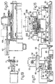
- transfer device 61 comprises a pair of pickup assemblies 73 and 74 for picking up pack 1, and which are carried by cursor 62 of linear actuator 63, are aligned along the X axis, are symmetrical with each other, and each comprise four vertical pins 76 ( Figure 16) spaced with the same spacing as holes 8 and 9 ( Figure 1) and so aligned as to simultaneously engage at least two of holes 8 and 9 regardless of the position of pack 1 in the stack.
- Each assembly 73, 74 comprises an unpinning mechanism 69, in turn, comprising a punch 71 ( Figure 18), which is located between pins 76 with the same spacing as holes 8 and 9, and which acts on respective pin 5, 6 to unpin the machined pack 1. More specifically, and as shown in Figure 18, punch 71 is located with one pin 76 to the right and three to the left.
- each of pins 76 is fitted eccentrically to a pin 77 ( Figure 19) which rotates inside a seat on a body or block 78 of assembly 73.
- Each pin 77 also slides a given distance inside the seat on block 78, and is pushed downwards by a compression spring 79.
- Each pin 77 is integral with a lateral arm 81, which is normally held by a spring 82 against a flange 83 of the piston rod 84 of a pneumatic cylinder 85; the four cylinders 85 are fitted in pairs to two sides 86 integral with block 78; and each flange 83 normally keeps the respective pin 77 so positioned that pin 76 lies in the plane of the axes of pins 77.
- Block 78 is integral with a vertical guide 87 ( Figures 14 and 17), which slides along a dovetailed guide 88 fitted to a frame 89; and block 78 is also integral with an appendix 91, which extends through an opening in frame 89 and is connected to the vertical piston rod 92 of a pneumatic cylinder 93 fitted to frame 89 and for moving block 78 vertically.
- Punch 71 ( Figure 18) is fitted to a further pin 94, which slides inside a seat on block 78 and is moved downwards by a high-speed actuator defined by a pneumatic cylinder 96 fitted to a plate 97 integral with frame 89.
- the front edge of table 18 comprises a channel 95 ( Figure 16) extending the whole length of table 18 along the X axis.
- Frame 89 also comprises a pair of lateral arms 98, the bottom ends of which are fitted with a pair of levers 99 (Figure 14).
- Each lever 99 is hinged to a respective horizontal pin 100, is normally set to the rest position shown in Figure 14, and is activated by a respective pneumatic cylinder 101 to rotate clockwise and engage the underside of a pack 1.
- Cylinder 96 of assembly 74 is fitted to a plate 102 ( Figure 13) in turn fitted to cursor 62; and cylinder 96 of assembly 73 is fitted to a slide 103, which moves along a guide 104 fitted to cursor 62 to adjust the distance between assemblies 73 and 74 according to the length M of pack 1.
- slide 103 comprises a nut screw 105 engaging a screw 106, which rotates on two supports of cursor 62; and one end of screw 106 is fitted to a handwheel 107 for manually adjusting the distance between assemblies 73 and 74.
- Transfer device 61 in the Figure 13-20 variation operates as follows.
- the control unit For each pack 1 to be loaded onto a fixture 38, the control unit first operates linear actuator 63 to position cursor 62, as before, over loading station 47 ( Figure 4). The control unit then operates both cylinders 93 ( Figure 13) to lower blocks 78; and, by virtue of springs 79, the pins 76 of assemblies 73 and 74 ( Figures 14 and 16) engage at least two holes 8 and two holes 9, depending on the position, along the Y axis, of pack 1 in the stack. By virtue of respective springs 79, the pins 76 encountering no holes 8, 9 ( Figure 3) rest simply on the upper surface of pack 1.
- Pack 1 is transferred along actuator 63 as in the previous case, and, to deposit pack 1 onto fixture 38, the control unit first operates cylinders 101 to release pack 1 from levers 99, and then operates cylinders 93 to lower pack 1 onto fixture 38. The control unit then operates cylinders 85 to free pack 1 completely from pins 76, and cylinders 93 are operated once more to raise blocks 78.
- pack 1 is clamped and transferred in the same way as for loading; and the packs are unpinned as device 61 is transferred along linear actuator 63.
- table 18 is positioned with channel 95 ( Figure 16) aligned vertically with the two punches 71 ( Figure 18) of assemblies 73 and 74.
- the control unit then operates the two high-speed actuators 96, which, by means of pins 94, push punches 71 downwards to push pins 5 and 6 out while pack 1 is locked positively by levers 99, so that pins 5 and 6 drop down into channel 95.
- linear actuator 63 comprises two end blocks 108, each of which travels along a respective prismatic guide 109 fitted to the corresponding crosspiece 52 of respective station 47, 48; and each crosspiece 52 is fitted with a pneumatic cylinder 110, the rod 111 of which is connected to the corresponding end block 108 of actuator 63.
- device 61 To access fixtures 38 in the rear row, device 61 is moved along actuator 63 as in the previous case; upon device 61 reaching the required fixture 38, pickup assemblies 73 and 74 are located on either side of the corresponding head 33 ( Figure 4) in the front row; and cylinders 110 are activated to move actuator 63, parallel to itself, from the continuous-line to the dash-line position in Figure 20 to bring pack 1 onto the rear-row fixture 38.
- the device for loading the packs onto the machine tool - particularly one featuring a number of machining heads - is simplified by eliminating the rack from which to remove the packs for transfer onto the table.
- unpinning packs 1 as soon as they are machined, by means of unpinning mechanisms 69 fitted to heads 33, provides for practically simultaneously unloading a whole row of packs 1 off table 18.
- the mechanism for unpinning the machined packs 1 may be eliminated, and the machined packs may be picked up by device 61 and stacked on platform 57 of unloading station 48 using the method according to the invention, and by operating transfer device 61 in the same way, only in reverse, as for loading the packs onto table 18.
- transfer device 61 may be guided along the X axis on a prismatic guide, and may be activated by a different type of actuator.
- device 61 may also be movable along the Y axis to allow for any phase displacement of packs 1 at loading station 47, without having to move table 18.
Landscapes
- Engineering & Computer Science (AREA)
- Manufacturing & Machinery (AREA)
- Microelectronics & Electronic Packaging (AREA)
- Mechanical Engineering (AREA)
- Feeding Of Workpieces (AREA)
- Stacking Of Articles And Auxiliary Devices (AREA)
- Perforating, Stamping-Out Or Severing By Means Other Than Cutting (AREA)
- Supply And Installment Of Electrical Components (AREA)
- Pile Receivers (AREA)
- Discharge By Other Means (AREA)
Applications Claiming Priority (2)
| Application Number | Priority Date | Filing Date | Title |
|---|---|---|---|
| IT97TO000872A IT1295460B1 (it) | 1997-10-02 | 1997-10-02 | Metodo per impilare pacchi di piastre di circuiti stampati e relativo dispositivo di carico e scarico di pacchi per una macchina utensile. |
| ITTO970872 | 1997-10-02 |
Publications (2)
| Publication Number | Publication Date |
|---|---|
| EP0906808A2 true EP0906808A2 (de) | 1999-04-07 |
| EP0906808A3 EP0906808A3 (de) | 2000-04-05 |
Family
ID=11416042
Family Applications (1)
| Application Number | Title | Priority Date | Filing Date |
|---|---|---|---|
| EP98118304A Withdrawn EP0906808A3 (de) | 1997-10-02 | 1998-09-28 | Verfahren zum Stapeln von Packen von Leiterplatten und entsprechende Vorrichtung zum Laden und Entladen von Packen für eine Werkzeugmaschine |
Country Status (4)
| Country | Link |
|---|---|
| US (1) | US6183190B1 (de) |
| EP (1) | EP0906808A3 (de) |
| JP (1) | JPH11220291A (de) |
| IT (1) | IT1295460B1 (de) |
Cited By (2)
| Publication number | Priority date | Publication date | Assignee | Title |
|---|---|---|---|---|
| US8097593B1 (en) | 2002-05-09 | 2012-01-17 | Oncothyreon Inc. | Lipid A and other carbohydrate ligand analogs |
| CN121531578A (zh) * | 2026-01-19 | 2026-02-13 | 四川英创力电子科技股份有限公司 | 一种电路板过水平线用叠板装置 |
Families Citing this family (22)
| Publication number | Priority date | Publication date | Assignee | Title |
|---|---|---|---|---|
| US6585967B2 (en) | 2001-07-05 | 2003-07-01 | Closure Medical Corporation | Adhesive treatment for tinea cruris |
| US6942875B2 (en) * | 2001-07-05 | 2005-09-13 | Closure Medical Corporation | Adhesive treatment for skin yeast infections |
| US6602496B2 (en) | 2001-07-05 | 2003-08-05 | Closure Medical Corporation | Adhesive treatment for tinea corporis |
| US6767552B2 (en) | 2001-07-05 | 2004-07-27 | Closure Medical Corporation | Adhesive treatment for oral fungal infection |
| US7516534B2 (en) * | 2001-11-25 | 2009-04-14 | Stresswave, Inc. | Method for attaching a nut element to a metal structure |
| JP3855879B2 (ja) * | 2002-08-07 | 2006-12-13 | 松下電器産業株式会社 | フレキシブルプリント基板の搬送用キャリアおよびフレキシブルプリント基板への電子部品実装方法 |
| FR2859466B1 (fr) * | 2003-09-10 | 2005-12-02 | Labadis | Dispositif de manutention de caisses et analogues |
| ITMI20050809A1 (it) * | 2005-05-04 | 2006-11-05 | Cem Spa | Dispositivo e procedimento di taglio di moduli continui |
| US20070040314A1 (en) * | 2005-07-12 | 2007-02-22 | Lkt Automation Sdn Bhd | Adjustable tool holder |
| TWI271837B (en) * | 2005-11-25 | 2007-01-21 | Ind Tech Res Inst | Clamping device for a flexible and method for fabricating the same |
| US20090241329A1 (en) * | 2008-03-28 | 2009-10-01 | Utac Thai Limited | Side rail remover |
| US20150128856A1 (en) * | 2013-11-14 | 2015-05-14 | Illinois Tool Works Inc. | Dispensing apparatus having transport system and method for transporting a substrate within the dispensing apparatus |
| US9504163B2 (en) * | 2014-08-28 | 2016-11-22 | Wojciech B. Kosmowski | Y axis beam positioning system for a PCB drilling machine |
| DE102014219060A1 (de) * | 2014-09-22 | 2016-03-24 | Homag Holzbearbeitungssysteme Gmbh | Bearbeitungsvorrichtung |
| CN106696475B (zh) * | 2015-11-13 | 2019-06-18 | 富泰华工业(深圳)有限公司 | 打印机及利用打印机打印电路板的方法 |
| JP7343303B2 (ja) * | 2019-05-26 | 2023-09-12 | 大船企業日本株式会社 | 基板の回収方法と、該回収方法の実施に供する加工後基板回収装置 |
| CN111573189A (zh) * | 2019-07-19 | 2020-08-25 | 维嘉数控科技(苏州)有限公司 | Pcb板输送系统 |
| TWI755906B (zh) * | 2020-10-23 | 2022-02-21 | 尚城科技股份有限公司 | 雙對稱結構交互式影像自動疊板機 |
| CN113814778B (zh) * | 2021-09-24 | 2022-09-30 | 西安航空职业技术学院 | 一种旁推取料式多零件工作台码放装置 |
| CN114126228B (zh) * | 2021-11-12 | 2023-02-03 | 东莞市吉宏五金科技有限公司 | 收板机、上pin针包胶及收板一体化生产设备 |
| CN114340189B (zh) * | 2022-01-13 | 2023-12-19 | 深圳市众芯合创科技有限公司 | 一种基于电路板的精修、检测、测试、包装设备 |
| CN116997094B (zh) * | 2023-09-08 | 2024-12-06 | 琥珀电子封装(苏州)有限公司 | Pcba封装装置及pcba偏移调整方法 |
Family Cites Families (13)
| Publication number | Priority date | Publication date | Assignee | Title |
|---|---|---|---|---|
| JPS61197143A (ja) * | 1985-02-25 | 1986-09-01 | Toshiba Mach Co Ltd | 板状ワ−クの加工機械 |
| JPS62105811A (ja) * | 1985-10-31 | 1987-05-16 | Mazda Motor Corp | 板状部材の位置決め搬送装置 |
| JPS6331959A (ja) * | 1986-07-23 | 1988-02-10 | Seikosha Co Ltd | ワ−ク位置決め装置 |
| EP0273086B1 (de) * | 1986-12-31 | 1991-02-27 | Willi Steiner | Satz von Bauelementen und Verwendung desselben |
| US5109584A (en) * | 1989-02-28 | 1992-05-05 | Hitachi Seiko Ltd. | Printed circuit board adapter supplying apparatus and method for use in printed circuit board drilling apparatus |
| JP2828488B2 (ja) * | 1990-05-23 | 1998-11-25 | 日立精工株式会社 | プリント基板加工装置 |
| US5101546A (en) * | 1990-11-30 | 1992-04-07 | Hitachi Seiko Ltd. | Apparatus for removing printed board |
| JPH0625931A (ja) * | 1992-07-07 | 1994-02-01 | Toyobo Co Ltd | 複合マルチフイラメント糸 |
| DE4338656C2 (de) * | 1993-11-12 | 1995-11-16 | Multiline International Europa | Vorrichtung zum Ausrichten von Leiterplatten und Bildträgern |
| DE19514163B4 (de) * | 1995-04-15 | 2005-12-29 | Atg Test Systems Gmbh & Co.Kg | Verfahren zum vollautomatischen Handhaben von elektrisch zu prüfenden Leiterplatten und Vorrichtung zum Ausführen dieses Verfahrens |
| US5692286A (en) * | 1995-10-02 | 1997-12-02 | Posulax S.A. | Method for shaping parts in one or more stacked board shaped elements and machine tool for implementing this method |
| US5768772A (en) * | 1996-05-17 | 1998-06-23 | International Business Machines Corporation | Pinstacking process and fixture |
| DE29712034U1 (de) * | 1997-07-09 | 1997-09-18 | Schmoll Maschinen GmbH, 63322 Rödermark | Automatisierte Leiterplatten-Bohrmaschine |
-
1997
- 1997-10-02 IT IT97TO000872A patent/IT1295460B1/it active IP Right Grant
-
1998
- 1998-09-28 EP EP98118304A patent/EP0906808A3/de not_active Withdrawn
- 1998-09-29 JP JP10312657A patent/JPH11220291A/ja not_active Withdrawn
- 1998-09-29 US US09/162,641 patent/US6183190B1/en not_active Expired - Fee Related
Cited By (3)
| Publication number | Priority date | Publication date | Assignee | Title |
|---|---|---|---|---|
| US8097593B1 (en) | 2002-05-09 | 2012-01-17 | Oncothyreon Inc. | Lipid A and other carbohydrate ligand analogs |
| CN121531578A (zh) * | 2026-01-19 | 2026-02-13 | 四川英创力电子科技股份有限公司 | 一种电路板过水平线用叠板装置 |
| CN121531578B (zh) * | 2026-01-19 | 2026-04-14 | 四川英创力电子科技股份有限公司 | 一种电路板过水平线用叠板装置 |
Also Published As
| Publication number | Publication date |
|---|---|
| US6183190B1 (en) | 2001-02-06 |
| IT1295460B1 (it) | 1999-05-12 |
| EP0906808A3 (de) | 2000-04-05 |
| JPH11220291A (ja) | 1999-08-10 |
| ITTO970872A1 (it) | 1999-04-02 |
Similar Documents
| Publication | Publication Date | Title |
|---|---|---|
| US6183190B1 (en) | Method of stacking packs of printed circuit boards and relative pack loading and unloading device for a machine tool | |
| US7131361B2 (en) | Workpiece-transfer device | |
| EP1810803A1 (de) | Maschine zur Bearbeitung von Holzelementen mit automatischer Ladung und Entladung dieser Elemente sowie Verfahren zum Laden dieser Elemente | |
| CN1155864A (zh) | 加工中心 | |
| CN111470330B (zh) | 工件堆叠装置 | |
| EP0138600B1 (de) | Werkzeugbereitstellungssystem für eine Werkzeugmaschine | |
| WO1992009382A1 (en) | Tape automated bonding feeder and lead forming apparatus | |
| KR102790088B1 (ko) | 기판 매거진의 로딩 및 언로딩 장치, 기판 매거진 시스템 | |
| CN210557932U (zh) | 一种基板隔板自动上料结构 | |
| CN116493901A (zh) | 一种萃盘上下料装置 | |
| US20080003084A1 (en) | High speed tray transfer system | |
| CN212412011U (zh) | 自动合片机 | |
| JPS60153308A (ja) | プリント板給排装置 | |
| CN216989936U (zh) | 板料加工装置 | |
| CN119057090A (zh) | 一种金属件自动化车削设备 | |
| CN117943291A (zh) | 柔板外观自动检测设备 | |
| US20090294249A1 (en) | Device For Transporting Workpiece Holders | |
| CN116936427A (zh) | 芯片翻转结构、整摞载具和芯片翻转一体机 | |
| KR200286751Y1 (ko) | 반도체패키지 제조 장비의 트레이 공급장치 | |
| EP0278608A2 (de) | Ansaug-Aufnahmevorrichtung für elektrische und elektronische Komponenten | |
| JP3566865B2 (ja) | 部品供給方法と装置、これを用いた部品装着装置 | |
| EP1479477A1 (de) | Werkzeugmaschine zum Bearbeiten von Werkstücken | |
| CN220055311U (zh) | 输送机构、下料装置及载板作业系统 | |
| CN116422650B (zh) | 一种等离子清洗设备 | |
| CN216871904U (zh) | 一种集成电路封装的生产线 |
Legal Events
| Date | Code | Title | Description |
|---|---|---|---|
| PUAI | Public reference made under article 153(3) epc to a published international application that has entered the european phase |
Free format text: ORIGINAL CODE: 0009012 |
|
| AK | Designated contracting states |
Kind code of ref document: A2 Designated state(s): AT BE CH DE DK FR GB IE IT LI LU NL SE |
|
| AX | Request for extension of the european patent |
Free format text: AL;LT;LV;MK;RO;SI |
|
| RAP1 | Party data changed (applicant data changed or rights of an application transferred) |
Owner name: BORGOTEC TECNOLOGIE PER L'AUTOMAZIONE S.P.A. |
|
| K1C1 | Correction of patent application (title page) published |
Effective date: 19990407 |
|
| PUAL | Search report despatched |
Free format text: ORIGINAL CODE: 0009013 |
|
| AK | Designated contracting states |
Kind code of ref document: A3 Designated state(s): AT BE CH CY DE DK ES FI FR GB GR IE IT LI LU MC NL PT SE |
|
| AX | Request for extension of the european patent |
Free format text: AL;LT;LV;MK;RO;SI |
|
| 17P | Request for examination filed |
Effective date: 20000926 |
|
| AKX | Designation fees paid |
Free format text: AT BE CH DE DK FR GB IE IT LI LU NL SE |
|
| STAA | Information on the status of an ep patent application or granted ep patent |
Free format text: STATUS: THE APPLICATION IS DEEMED TO BE WITHDRAWN |
|
| 18D | Application deemed to be withdrawn |
Effective date: 20020403 |