EP0906821B1 - Extrudeuse à vis - Google Patents
Extrudeuse à vis Download PDFInfo
- Publication number
- EP0906821B1 EP0906821B1 EP98115392A EP98115392A EP0906821B1 EP 0906821 B1 EP0906821 B1 EP 0906821B1 EP 98115392 A EP98115392 A EP 98115392A EP 98115392 A EP98115392 A EP 98115392A EP 0906821 B1 EP0906821 B1 EP 0906821B1
- Authority
- EP
- European Patent Office
- Prior art keywords
- screw
- casing
- extrusion machine
- machine according
- type extrusion
- Prior art date
- Legal status (The legal status is an assumption and is not a legal conclusion. Google has not performed a legal analysis and makes no representation as to the accuracy of the status listed.)
- Expired - Lifetime
Links
Images

Classifications
-
- B—PERFORMING OPERATIONS; TRANSPORTING
- B29—WORKING OF PLASTICS; WORKING OF SUBSTANCES IN A PLASTIC STATE IN GENERAL
- B29C—SHAPING OR JOINING OF PLASTICS; SHAPING OF MATERIAL IN A PLASTIC STATE, NOT OTHERWISE PROVIDED FOR; AFTER-TREATMENT OF THE SHAPED PRODUCTS, e.g. REPAIRING
- B29C48/00—Extrusion moulding, i.e. expressing the moulding material through a die or nozzle which imparts the desired form; Apparatus therefor
- B29C48/25—Component parts, details or accessories; Auxiliary operations
- B29C48/36—Means for plasticising or homogenising the moulding material or forcing it through the nozzle or die
- B29C48/50—Details of extruders
- B29C48/503—Extruder machines or parts thereof characterised by the material or by their manufacturing process
-
- B—PERFORMING OPERATIONS; TRANSPORTING
- B29—WORKING OF PLASTICS; WORKING OF SUBSTANCES IN A PLASTIC STATE IN GENERAL
- B29C—SHAPING OR JOINING OF PLASTICS; SHAPING OF MATERIAL IN A PLASTIC STATE, NOT OTHERWISE PROVIDED FOR; AFTER-TREATMENT OF THE SHAPED PRODUCTS, e.g. REPAIRING
- B29C48/00—Extrusion moulding, i.e. expressing the moulding material through a die or nozzle which imparts the desired form; Apparatus therefor
- B29C48/25—Component parts, details or accessories; Auxiliary operations
- B29C48/36—Means for plasticising or homogenising the moulding material or forcing it through the nozzle or die
- B29C48/50—Details of extruders
- B29C48/68—Barrels or cylinders
- B29C48/682—Barrels or cylinders for twin screws
-
- B—PERFORMING OPERATIONS; TRANSPORTING
- B29—WORKING OF PLASTICS; WORKING OF SUBSTANCES IN A PLASTIC STATE IN GENERAL
- B29C—SHAPING OR JOINING OF PLASTICS; SHAPING OF MATERIAL IN A PLASTIC STATE, NOT OTHERWISE PROVIDED FOR; AFTER-TREATMENT OF THE SHAPED PRODUCTS, e.g. REPAIRING
- B29C48/00—Extrusion moulding, i.e. expressing the moulding material through a die or nozzle which imparts the desired form; Apparatus therefor
- B29C48/25—Component parts, details or accessories; Auxiliary operations
- B29C48/256—Exchangeable extruder parts
- B29C48/2562—Mounting or handling of the die
-
- B—PERFORMING OPERATIONS; TRANSPORTING
- B29—WORKING OF PLASTICS; WORKING OF SUBSTANCES IN A PLASTIC STATE IN GENERAL
- B29C—SHAPING OR JOINING OF PLASTICS; SHAPING OF MATERIAL IN A PLASTIC STATE, NOT OTHERWISE PROVIDED FOR; AFTER-TREATMENT OF THE SHAPED PRODUCTS, e.g. REPAIRING
- B29C48/00—Extrusion moulding, i.e. expressing the moulding material through a die or nozzle which imparts the desired form; Apparatus therefor
- B29C48/25—Component parts, details or accessories; Auxiliary operations
- B29C48/36—Means for plasticising or homogenising the moulding material or forcing it through the nozzle or die
- B29C48/50—Details of extruders
- B29C48/68—Barrels or cylinders
- B29C48/6801—Barrels or cylinders characterised by the material or their manufacturing process
-
- B—PERFORMING OPERATIONS; TRANSPORTING
- B29—WORKING OF PLASTICS; WORKING OF SUBSTANCES IN A PLASTIC STATE IN GENERAL
- B29C—SHAPING OR JOINING OF PLASTICS; SHAPING OF MATERIAL IN A PLASTIC STATE, NOT OTHERWISE PROVIDED FOR; AFTER-TREATMENT OF THE SHAPED PRODUCTS, e.g. REPAIRING
- B29C48/00—Extrusion moulding, i.e. expressing the moulding material through a die or nozzle which imparts the desired form; Apparatus therefor
- B29C48/03—Extrusion moulding, i.e. expressing the moulding material through a die or nozzle which imparts the desired form; Apparatus therefor characterised by the shape of the extruded material at extrusion
Definitions
- the invention is directed to a screw machine according to the preamble of claim 1.
- a generic screw machine is known from DE 39 36 085 A1.
- the problem basically arises with such screw machines on that when heating the machine and also during operation Temperature differences between the housing sections and the tie rods occur. If, especially with larger and heavier machines, a uniform temperature distribution is not guaranteed, tightness problems can occur.
- DE 29 52 348 A1 describes a connection of housing sections, in particular for twin screw extruders, described, the housing sections by means of prestressed, in two to the cylinder double bores axially parallel and diametrically opposed planes Threaded bolts are connected to each other. To achieve the The threaded bolts are heated so that they cool down sets the desired preload due to the shortening of the length. These measures are only possible with smaller machines if the tie rods in closed holes and relatively close to the double cylinder holes are so that the temperature differences are very small are.
- the invention is based, in screw machines the task Generic type, in particular with larger machines, under Maintaining the basic advantages of a tie rod construction high tightness at all operating temperatures, including during Heating process and in the heated state to achieve.
- the provision of a spring arrangement according to the invention is similar to that which occurs uneven expansion due to a non-uniform temperature distribution in an optimal manner and ensures a high level of tightness for sure.
- the plate spring packages provided according to claim 2 enable realizing a very favorable displacement-force characteristic of the spring arrangement, in particular to design the spring arrangement so that on the one hand Utilization of approx. 50% of the maximum spring travel sufficient sealing force is applied and on the other hand about 25% of the remaining travel is sufficient, the differences in length due to the different thermal expansion to record. The remaining 25% of the maximum possible Travel can remain as a reserve.
- Claim 3 enters optimal ratio of the expansion of the tie rod and disc spring package again.
- control pin provided according to claims 8 and 9 enables one optical control of the preload such that the correct preload is reached when the edge of a placed on the disc spring package Thrust washer reached the tip of the control pin.
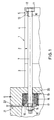
- a screw machine 1 shown in the drawing comprises a Screw housing 2, of which housing sections 3 and 4, an end plate 5 and a front part 6 are shown.
- the housing sections 3, 4 and the end plate 5 and the front part 6 are connected via tie rods 7, the outside in recesses 8 of the housing 2 are arranged parallel to its central longitudinal axis 9. How 2 can be removed, the recesses 8 of the housing 2 are open laterally, so that the tie rods 7 are transverse to their own longitudinal direction, i.e. across can be inserted into the recesses 8 to the axis 9.
- the tie rods 7 have a first end on the right in FIG. 1 illustrated thread 10, which also in a laterally open recess 11 of the end plate 5 opens, in this area a nut 12th is screwed, which is supported on the bottom 13 of the recess 11.
- a thread 14 is provided on which a nut 15 is screwed.
- the nut 15 is supported against a thrust washer 16 which on one Snap ring 17 is present.
- a disc spring assembly is connected to the thrust washer 16 18 on, with a shim 19 between this plate spring package 18 and an inner end wall 20 of the end part 6 are provided is.
- the nut 15 with the thrust washer 16 forms a first abutment on Tie rod 7 and the shim 19 with the end wall 20 a second Abutment on the housing 2 each for the plate spring package 18.
- the Snap ring 17 prevents the pressure plate 16 and the from falling out Disc spring pack 18 when the tie rod 7 is removed.
- the front part 6 is of a bore 21 in the direction perpendicular to Longitudinal axis 9 of the housing 2 passes through, in which a control pin 22nd is used, which extends into the area of the pressure plate 16 and one Control of proper assembly allows.
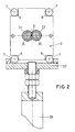
- the housing 2 two penetrating has in cross section circular longitudinal recesses 23, 24, in which Screws 25, 26 are arranged.
- the screw machine 1 shown overall in FIG. 3 is concerned an extruder. It has one supported on a foundation 29 Underframe 30 on which a reduction and distribution gear 31 is supported. On the input side of the transmission 31 is a drive motor 32 flanged with a clutch; on the output side of the gearbox 31 is the front part 6, a so-called lantern, attached to which The housing 2 forming the process part is attached.
- This housing 2 consists of the housing sections 3 and 4 and further housing sections.
- the working direction 33 corresponds to the longitudinal direction of the housing 2.
- On the first housing section 3 in the working direction 33 is a Inlet 34 is provided for material to be treated.
- the one in the working direction 33 last housing section is provided with a nozzle head 35 through the treated material emerges.
- the nozzle head 35 lies on the end plate 5 on.
- the process part forming the housing 2 is by means of a support trained receptacle 28 supported on the base 30.
- the lower Tie rods 7 lie on the crossbar or beam Table 27 on.
- the ratio of the elongation defined in mm / N from tie rod 7 to disc spring package 18 is in the range of 1: 1.5 to 1: 5.
- the elongation of the plate spring assembly 18 in each case 1.5 to 5 times greater than the elongation of the tie rods 7, so that changes in length of the tie rods 7, in particular due to thermally induced different expansions of housing 2 and tie rods 7, without much change in the preload the tie rod 7 can be collected.
Landscapes
- Engineering & Computer Science (AREA)
- Mechanical Engineering (AREA)
- Manufacturing & Machinery (AREA)
- Extrusion Moulding Of Plastics Or The Like (AREA)
- Formation And Processing Of Food Products (AREA)
- Structure Of Belt Conveyors (AREA)
- Control Of Conveyors (AREA)
- Investigating Strength Of Materials By Application Of Mechanical Stress (AREA)
- Extrusion Of Metal (AREA)
- Heat-Exchange Devices With Radiators And Conduit Assemblies (AREA)
- Screw Conveyors (AREA)
Claims (9)
- Extrudeuse à vis comportant un boítier (2) composite présentant des tronçons (3, 4) de boítier juxtaposés les uns aux autres en direction longitudinale, les tronçons (3, 4) de boítier étant serrés fermement les uns contre les autres par une multitude de tirants d'ancrage (7) qui s'étendent sur la face extérieure du boítier en parallèle les uns aux autres en direction longitudinale du boítier (2) et qui sont agencés dans des évidements (8) du boítier (2) ouverts vers l'extérieur, caractérisée en ce que les tirants d'ancrage (7) sont sollicités chacun en direction longitudinale par un agencement à ressort précontraint.
- Extrudeuse à vis selon la revendication 1, caractérisée en ce que l'agencement à ressort est formé par un empilement de rondelles Belleville (18) posé sur le tirant d'ancrage (7) respectif.
- Extrudeuse à vis selon la revendication 2, caractérisée en ce que le rapport entre l'extension du tirant d'ancrage (7) et l'extension de l'empilement de rondelles Belleville (18) est dans la plage de 1:1,5 à 1:5.
- Extrudeuse à vis selon la revendication 2, caractérisée en ce que l'empilement de rondelles Belleville (18) prend appui d'une part sur une paroi frontale (20) associée au boítier (2) et d'autre part au moins indirectement sur un écrou vissé sur un filetage (14) à l'extrémité de chaque tirant d'ancrage (7).
- Extrudeuse à vis selon la revendication 2, caractérisée en ce que l'empilement de rondelles Belleville (18) est soutenu par un disque d'égalisation (19).
- Extrudeuse à vis selon la revendication 1, caractérisée en ce que des tirants d'ancrage (7) inférieurs sont en appui sur un logement (28).
- Extrudeuse à vis selon la revendication 2, caractérisée en ce qu'il est prévu un dispositif de contrôle visuel pour vérifier la précontrainte d'un empilement de rondelles Belleville (18).
- Extrudeuse à vis selon la revendication 7, caractérisée en ce qu'il est prévu une goupille de contrôle (22) pour vérifier la précontrainte d'un empilement de rondelles Belleville (18), laquelle s'étend avec une extrémité jusque dans la région de l'extrémité extérieure libre de l'empilement de rondelles de Belleville (18).
- Extrudeuse à vis selon la revendication 8, caractérisée en ce que la goupille de contrôle (22) traverse un perçage (21) du boítier (2) qui s'étend sensiblement perpendiculairement à la direction longitudinale du boítier (2).
Applications Claiming Priority (2)
| Application Number | Priority Date | Filing Date | Title |
|---|---|---|---|
| DE19740836 | 1997-09-17 | ||
| DE19740836 | 1997-09-17 |
Publications (2)
| Publication Number | Publication Date |
|---|---|
| EP0906821A1 EP0906821A1 (fr) | 1999-04-07 |
| EP0906821B1 true EP0906821B1 (fr) | 2001-11-21 |
Family
ID=7842604
Family Applications (1)
| Application Number | Title | Priority Date | Filing Date |
|---|---|---|---|
| EP98115392A Expired - Lifetime EP0906821B1 (fr) | 1997-09-17 | 1998-08-17 | Extrudeuse à vis |
Country Status (7)
| Country | Link |
|---|---|
| EP (1) | EP0906821B1 (fr) |
| KR (1) | KR19990029887A (fr) |
| AT (1) | ATE209093T1 (fr) |
| BR (1) | BR9803468A (fr) |
| DE (2) | DE59802693D1 (fr) |
| ES (1) | ES2168711T3 (fr) |
| TR (1) | TR199801768A2 (fr) |
Families Citing this family (2)
| Publication number | Priority date | Publication date | Assignee | Title |
|---|---|---|---|---|
| DE202004019291U1 (de) * | 2004-12-14 | 2005-02-24 | Thread Guard Technology Ltd. | Vorrichtung zur Abstützung von Rohren |
| DE102010027664A1 (de) * | 2010-07-19 | 2012-01-19 | Thermo Electron (Karlsruhe) Gmbh | Extruder |
Family Cites Families (5)
| Publication number | Priority date | Publication date | Assignee | Title |
|---|---|---|---|---|
| DD141134A1 (de) * | 1979-02-05 | 1980-04-16 | Siegfried Schreiter | Zylinderstueckverbindung,insbesondere fuer doppelschneckenextruder |
| DE3810079A1 (de) * | 1988-03-25 | 1989-10-05 | Bayer Ag | Schneckenmaschine mit keramischem verfahrensteil |
| FR2632892B1 (fr) * | 1988-06-21 | 1990-12-07 | Clextral | Fourreau pour machine de traitement de matieres en particulier pour une ex-trudeuse a vis |
| DE3936085A1 (de) * | 1989-10-30 | 1991-05-02 | Blach Josef A | Schneckenwellenmaschine mit zusammengesetztem gehaeuse |
| JP2638552B2 (ja) * | 1995-03-31 | 1997-08-06 | 株式会社神戸製鋼所 | 押出機のバレル接続装置 |
-
1998
- 1998-08-17 EP EP98115392A patent/EP0906821B1/fr not_active Expired - Lifetime
- 1998-08-17 DE DE59802693T patent/DE59802693D1/de not_active Expired - Lifetime
- 1998-08-17 ES ES98115392T patent/ES2168711T3/es not_active Expired - Lifetime
- 1998-08-17 AT AT98115392T patent/ATE209093T1/de not_active IP Right Cessation
- 1998-08-17 DE DE19837171A patent/DE19837171A1/de not_active Withdrawn
- 1998-09-07 TR TR1998/01768A patent/TR199801768A2/xx unknown
- 1998-09-16 BR BR9803468-5A patent/BR9803468A/pt not_active Application Discontinuation
- 1998-09-17 KR KR1019980038400A patent/KR19990029887A/ko not_active Withdrawn
Also Published As
| Publication number | Publication date |
|---|---|
| BR9803468A (pt) | 1999-11-23 |
| TR199801768A2 (xx) | 1999-04-21 |
| EP0906821A1 (fr) | 1999-04-07 |
| KR19990029887A (ko) | 1999-04-26 |
| DE19837171A1 (de) | 1999-03-18 |
| ATE209093T1 (de) | 2001-12-15 |
| DE59802693D1 (de) | 2002-02-21 |
| ES2168711T3 (es) | 2002-06-16 |
Similar Documents
| Publication | Publication Date | Title |
|---|---|---|
| DE3931397C2 (fr) | ||
| DE19615505C2 (de) | Doppelplattenkörper | |
| DE2836498A1 (de) | Nichtmetallische kette | |
| EP0147736B1 (fr) | Section de boîtier pour boudineuse à deux vis | |
| DE4343658A1 (de) | Gleitverbindungsvorrichtung zwischen zwei Teilen, die starken mechanischen und thermischen Belastungen unterliegen | |
| DE4302007C1 (de) | Einrichtung zum Verbinden eines Motorblocks mit einem Getriebeblock | |
| EP0052310B1 (fr) | Dispositif de mise sous tension d'une chenille, en particulier pour un tracteur chenillé | |
| DE4316913C2 (de) | Breitschlitzdüse | |
| EP0767315A2 (fr) | Palier de vilebrequin pour moteur à combustion | |
| EP0906821B1 (fr) | Extrudeuse à vis | |
| DE2936630C2 (de) | Kolben für eine Brennkraftmaschine | |
| EP3587002A1 (fr) | Fermeture coulissante pour un récipient métallurgique, de préférence un récipient de distribution pour une installation de coulée continue | |
| EP1002634B1 (fr) | Machine à plusieurs vis | |
| EP1707759A2 (fr) | Carter d'une turbomachine | |
| DE102004021644A1 (de) | Wälzkörpergewindetrieb mit Rückführhülse | |
| DE2715076C3 (de) | Rohrweite für Schiffs-Wellenleitung | |
| DE4018094C2 (fr) | ||
| DE3130229C2 (de) | Mehrschneidenwerkzeug | |
| EP0773376A1 (fr) | Palier de vilebrequin | |
| CH687710A5 (de) | Halterung fuer Spinn- oder Zwirnspindeln. | |
| DE4138441C2 (de) | Preßwerkzeug für eine Stauchpresse zur Reduzierung der Brammenbreite in Warmbreitband-Vorstraßen | |
| EP0742698B1 (fr) | Ecarteur a vis | |
| DE2952348A1 (de) | Zylinderstueckverbindung, insbesondere fuer doppelschneckenextruder | |
| EP1270967B1 (fr) | Bielle avec une extrémité supérieure rapportée | |
| CH647101A5 (en) | Electrical connecting device on a plastic part and a method for its production |
Legal Events
| Date | Code | Title | Description |
|---|---|---|---|
| PUAI | Public reference made under article 153(3) epc to a published international application that has entered the european phase |
Free format text: ORIGINAL CODE: 0009012 |
|
| AK | Designated contracting states |
Kind code of ref document: A1 Designated state(s): AT BE CH DE ES FI FR GB IT LI NL SE |
|
| AX | Request for extension of the european patent |
Free format text: AL;LT;LV;MK;RO;SI |
|
| 17P | Request for examination filed |
Effective date: 19990216 |
|
| AKX | Designation fees paid |
Free format text: AT BE CH DE ES FI FR GB IT LI NL SE |
|
| 17Q | First examination report despatched |
Effective date: 20000804 |
|
| GRAG | Despatch of communication of intention to grant |
Free format text: ORIGINAL CODE: EPIDOS AGRA |
|
| RAP1 | Party data changed (applicant data changed or rights of an application transferred) |
Owner name: COPERION WERNER & PFLEIDERER GMBH & CO. KG |
|
| GRAG | Despatch of communication of intention to grant |
Free format text: ORIGINAL CODE: EPIDOS AGRA |
|
| GRAH | Despatch of communication of intention to grant a patent |
Free format text: ORIGINAL CODE: EPIDOS IGRA |
|
| GRAA | (expected) grant |
Free format text: ORIGINAL CODE: 0009210 |
|
| AK | Designated contracting states |
Kind code of ref document: B1 Designated state(s): AT BE CH DE ES FI FR GB IT LI NL SE |
|
| PG25 | Lapsed in a contracting state [announced via postgrant information from national office to epo] |
Ref country code: FI Free format text: LAPSE BECAUSE OF FAILURE TO SUBMIT A TRANSLATION OF THE DESCRIPTION OR TO PAY THE FEE WITHIN THE PRESCRIBED TIME-LIMIT Effective date: 20011121 |
|
| REF | Corresponds to: |
Ref document number: 209093 Country of ref document: AT Date of ref document: 20011215 Kind code of ref document: T |
|
| REG | Reference to a national code |
Ref country code: CH Ref legal event code: EP |
|
| REG | Reference to a national code |
Ref country code: GB Ref legal event code: IF02 |
|
| GBT | Gb: translation of ep patent filed (gb section 77(6)(a)/1977) |
Effective date: 20020121 |
|
| PG25 | Lapsed in a contracting state [announced via postgrant information from national office to epo] |
Ref country code: SE Free format text: LAPSE BECAUSE OF FAILURE TO SUBMIT A TRANSLATION OF THE DESCRIPTION OR TO PAY THE FEE WITHIN THE PRESCRIBED TIME-LIMIT Effective date: 20020221 |
|
| REF | Corresponds to: |
Ref document number: 59802693 Country of ref document: DE Date of ref document: 20020221 |
|
| REG | Reference to a national code |
Ref country code: ES Ref legal event code: FG2A Ref document number: 2168711 Country of ref document: ES Kind code of ref document: T3 |
|
| PGFP | Annual fee paid to national office [announced via postgrant information from national office to epo] |
Ref country code: CH Payment date: 20020708 Year of fee payment: 5 |
|
| PLBQ | Unpublished change to opponent data |
Free format text: ORIGINAL CODE: EPIDOS OPPO |
|
| PLBI | Opposition filed |
Free format text: ORIGINAL CODE: 0009260 |
|
| PG25 | Lapsed in a contracting state [announced via postgrant information from national office to epo] |
Ref country code: AT Free format text: LAPSE BECAUSE OF NON-PAYMENT OF DUE FEES Effective date: 20020817 |
|
| PGFP | Annual fee paid to national office [announced via postgrant information from national office to epo] |
Ref country code: ES Payment date: 20020826 Year of fee payment: 5 |
|
| PLBF | Reply of patent proprietor to notice(s) of opposition |
Free format text: ORIGINAL CODE: EPIDOS OBSO |
|
| 26 | Opposition filed |
Opponent name: LEISTRITZ AKTIENGESELLSCHAFT Effective date: 20020806 |
|
| NLR1 | Nl: opposition has been filed with the epo |
Opponent name: LEISTRITZ AKTIENGESELLSCHAFT |
|
| PLBF | Reply of patent proprietor to notice(s) of opposition |
Free format text: ORIGINAL CODE: EPIDOS OBSO |
|
| PLBF | Reply of patent proprietor to notice(s) of opposition |
Free format text: ORIGINAL CODE: EPIDOS OBSO |
|
| PG25 | Lapsed in a contracting state [announced via postgrant information from national office to epo] |
Ref country code: ES Free format text: LAPSE BECAUSE OF NON-PAYMENT OF DUE FEES Effective date: 20030818 |
|
| PGFP | Annual fee paid to national office [announced via postgrant information from national office to epo] |
Ref country code: NL Payment date: 20030818 Year of fee payment: 6 |
|
| PGFP | Annual fee paid to national office [announced via postgrant information from national office to epo] |
Ref country code: BE Payment date: 20030827 Year of fee payment: 6 |
|
| PG25 | Lapsed in a contracting state [announced via postgrant information from national office to epo] |
Ref country code: LI Free format text: LAPSE BECAUSE OF NON-PAYMENT OF DUE FEES Effective date: 20030831 Ref country code: CH Free format text: LAPSE BECAUSE OF NON-PAYMENT OF DUE FEES Effective date: 20030831 |
|
| PLBD | Termination of opposition procedure: decision despatched |
Free format text: ORIGINAL CODE: EPIDOSNOPC1 |
|
| REG | Reference to a national code |
Ref country code: CH Ref legal event code: PL |
|
| PLBM | Termination of opposition procedure: date of legal effect published |
Free format text: ORIGINAL CODE: 0009276 |
|
| STAA | Information on the status of an ep patent application or granted ep patent |
Free format text: STATUS: OPPOSITION PROCEDURE CLOSED |
|
| 27C | Opposition proceedings terminated |
Effective date: 20040222 |
|
| PG25 | Lapsed in a contracting state [announced via postgrant information from national office to epo] |
Ref country code: BE Free format text: LAPSE BECAUSE OF NON-PAYMENT OF DUE FEES Effective date: 20040831 |
|
| NLR2 | Nl: decision of opposition |
Effective date: 20040222 |
|
| REG | Reference to a national code |
Ref country code: ES Ref legal event code: FD2A Effective date: 20030818 |
|
| BERE | Be: lapsed |
Owner name: *COPERION WERNER & PFLEIDERER G.M.B.H. & CO. K.G. Effective date: 20040831 |
|
| PG25 | Lapsed in a contracting state [announced via postgrant information from national office to epo] |
Ref country code: NL Free format text: LAPSE BECAUSE OF NON-PAYMENT OF DUE FEES Effective date: 20050301 |
|
| NLV4 | Nl: lapsed or anulled due to non-payment of the annual fee |
Effective date: 20050301 |
|
| BERE | Be: lapsed |
Owner name: *COPERION WERNER & PFLEIDERER G.M.B.H. & CO. K.G. Effective date: 20040831 |
|
| REG | Reference to a national code |
Ref country code: FR Ref legal event code: PLFP Year of fee payment: 18 |
|
| REG | Reference to a national code |
Ref country code: FR Ref legal event code: PLFP Year of fee payment: 19 |
|
| REG | Reference to a national code |
Ref country code: FR Ref legal event code: PLFP Year of fee payment: 20 |
|
| PGFP | Annual fee paid to national office [announced via postgrant information from national office to epo] |
Ref country code: FR Payment date: 20170823 Year of fee payment: 20 Ref country code: IT Payment date: 20170824 Year of fee payment: 20 Ref country code: GB Payment date: 20170824 Year of fee payment: 20 |
|
| PGFP | Annual fee paid to national office [announced via postgrant information from national office to epo] |
Ref country code: DE Payment date: 20171019 Year of fee payment: 20 |
|
| REG | Reference to a national code |
Ref country code: DE Ref legal event code: R071 Ref document number: 59802693 Country of ref document: DE |
|
| REG | Reference to a national code |
Ref country code: GB Ref legal event code: PE20 Expiry date: 20180816 |
|
| PG25 | Lapsed in a contracting state [announced via postgrant information from national office to epo] |
Ref country code: GB Free format text: LAPSE BECAUSE OF EXPIRATION OF PROTECTION Effective date: 20180816 |