EP0906825A2 - Method for operating a rotary press and device for carrying out the method - Google Patents
Method for operating a rotary press and device for carrying out the method Download PDFInfo
- Publication number
- EP0906825A2 EP0906825A2 EP98115978A EP98115978A EP0906825A2 EP 0906825 A2 EP0906825 A2 EP 0906825A2 EP 98115978 A EP98115978 A EP 98115978A EP 98115978 A EP98115978 A EP 98115978A EP 0906825 A2 EP0906825 A2 EP 0906825A2
- Authority
- EP
- European Patent Office
- Prior art keywords
- printing
- imaging
- printing form
- impression
- press
- Prior art date
- Legal status (The legal status is an assumption and is not a legal conclusion. Google has not performed a legal analysis and makes no representation as to the accuracy of the status listed.)
- Granted
Links
Images


Classifications
-
- B—PERFORMING OPERATIONS; TRANSPORTING
- B41—PRINTING; LINING MACHINES; TYPEWRITERS; STAMPS
- B41F—PRINTING MACHINES OR PRESSES
- B41F7/00—Rotary lithographic machines
- B41F7/02—Rotary lithographic machines for offset printing
-
- B—PERFORMING OPERATIONS; TRANSPORTING
- B41—PRINTING; LINING MACHINES; TYPEWRITERS; STAMPS
- B41P—INDEXING SCHEME RELATING TO PRINTING, LINING MACHINES, TYPEWRITERS, AND TO STAMPS
- B41P2217/00—Printing machines of special types or for particular purposes
- B41P2217/10—Printing machines of special types or for particular purposes characterised by their constructional features
- B41P2217/13—Machines with double or multiple printing units for "flying" printing plates exchange
-
- B—PERFORMING OPERATIONS; TRANSPORTING
- B41—PRINTING; LINING MACHINES; TYPEWRITERS; STAMPS
- B41P—INDEXING SCHEME RELATING TO PRINTING, LINING MACHINES, TYPEWRITERS, AND TO STAMPS
- B41P2227/00—Mounting or handling printing plates; Forming printing surfaces in situ
- B41P2227/70—Forming the printing surface directly on the form cylinder
Definitions
- the invention relates to a method for operating a rotary printing press at least two printing forms that can be imaged in the printing press, with which after a single illustration several prints can be carried out, according to Preamble of claim 1, and an apparatus for performing the method.
- DE-PS 28 44 418 is a web-fed rotary printing press with flying Print image change described in an impression unit, that is, when Reaching a certain edition with a first impression of the moment printing printing unit turned off and another printing unit of the impression unit is put into operation without machine downtime. During the further Printing unit works, the parked printing unit can be used for the next impression to get prepared.
- An illustration of printing forms in the printing press is here not provided, so that the cost of printing a small print run Prepress, e.g. B. the photochemical plate copy, a comparative represent a large proportion of the total costs. Automation of the Printing plate change can only be done with considerable technical effort to reach.
- the invention has for its object a method for operating a Rotary printing machine, through which partial runs of short runs are also possible economical with low waste and low machine utilization can be produced, and to provide a device for carrying out the method.
- the method for operating a Rotary printing press with at least two images that can be imaged in the printing press Printing forms with which several prints after a single illustration are feasible characterized in that during printing with the first Printing form the second printing form is illustrated.
- the illustration of the second Printing form takes place in particular for printing with the first printing form subsequent printing with the second printing form.
- an apparatus for performing the method is distinguished characterized in that the first printing form a first imaging device and the a second imaging device is assigned to a second printing form.
- a further device for pressure control of the Process characterized in that the first printing form and the second printing form only common imaging device is assigned, which for Illustration of the first and the second printing form can be used.
- the method can be used in the operation of rotary and rotary Use sheet-fed rotary printing machines.
- the devices are in these Machines can be used.
- the invention In contrast to the dynamic or erasable forms in as Output devices used for personal computers, e.g. B. after the electrographic Principle working printers and plotters, the invention relates to unique imageable - i.e. assignable to the master system - printing forms with one storable, non-erasable print image.
- These printing forms can be in the form of a Pressure plate, a sleeve or a curable fluid layer or preferably a print film that can be unwound and wound up can be applied to printing form cylinders.
- the printing forms can be used as offset printing forms, e.g. B. as conventional Wet offset printing forms or as dry offset printing forms working without a dampening agent, and also be designed as printing forms of direct planographic printing (dilitho).
- the direct imaging of the printing forms can be according to one computer-to-press - imaging process that uses a local or Pixel by pixel, preferably high-energy, radiation and a subsequent one manual or automatic cleaning of the printing form from Imaging residues, e.g. B. thermally decompose a non-printing material Layer of the printing form, so that a printing layer at the image points is exposed and activated.
- the non-printing layer of the printing form can be a Silicone layer and the printing layer an infrared absorption layer.
- the printing form can be cleaned by means of a cleaning device or by the substrate.
- the one to be printed on below or made of a material specially designed for cleaning Printing material can be used.
- the imaging residues can be from Printing material immediately during the start of printing z. B. by a few Sheets becoming waste, or in a preceding sheet Cleaning run can be included.
- the imaging process is one that follows the actual imaging process Cleaning process not necessary. Instead, other processes can Make the printing form ready for printing and attach the images.
- the complete illustration of the printing form requires depending on the respective Imaging process a certain amount of time, z. B. a total of 12 minutes, the irradiation of the printing form and the cleaning can take 6 minutes.
- a total print run can consist of a first partial print run, which is to be provided with a printed image or impression, and a second Partial edition, which are provided with a different print image or impression image should exist.
- the first printing form can print the first printing or impression image
- the second Illustrated printing form in the printing press e.g. B. irradiated and cleaned.
- the production of the first partial edition requires very little time, in example above less than 12 min., it is possible that the imaging of the second printing form is not yet complete when the first partial edition is completed is completed, so that the printing press for the duration of the finished imaging can stand still. In this case, the imaging of the second printing form takes place partially while printing with the first printing form. As a rule, this requires Printing the first partial edition, however, far more time than that Imaging process takes up so that it is complete can be carried out during the printing of the first partial edition.
- a the second printing form comprising second printing device via a drive Production speed accelerated, the second printing device with the Printing machine speed synchronized and to the main drive of the Coupled printing machine and brought the second printing form into printing position.
- the first printing form can be brought out of the printing position and the the first printing form comprising the first printing device from the main drive be uncoupled so that the first printing device to a standstill or can be decelerated to reach a lower speed (creep speed).
- the flying change described above can be done continuously Operation of a third or more others included in the printing press Printing devices or printing units take place.
- Printing units can be the actual print image of the total print run of the order are printed, the first and second printing device additional impressions in this actual print image can be printed.
- the other printing units can be conventional Include printing forms, the z. B. by means of plate copying outside the printing press and cannot be imaged within the printing press.
- alternate images can be used and an alternate use of the first printing form and the second printing form respectively.
- the method can also be done using more are carried out as two printing forms that can be imaged in the printing press, where z. B. a first printing form is in use, while a second printing form and a third printing form can be illustrated.
- a first printing form is in use
- a second printing form and a third printing form can be illustrated.
- the first and the second Imaging device of the device for performing the method can by a separately assigned one or by a single selectable one common electronic control device can be controlled.
- the Control device can e.g. B. contain a microprocessor and bitmap files from electronic publishing systems, e.g. B. from a raster image processor, take over, these digital data to the z. B. a line of 11 Including laser diodes or electroerosive spark generating electrodes Print heads of the imaging devices are forwarded.
- a common imaging device of the device according to the invention can by optional attachment, e.g. B. a change of a first, the first Printing form associated holder in a second, the second printing form assigned bracket to be assigned to the respective printing form.
- the common imaging device in a first position Imaging of the first printing form and in a second position for imaging the second printing form adjustable, e.g. B.
- displaceable, rotatable or pivotable be.
- a device can be used to carry out a special embodiment of the inventive method, which includes that in an already printed Print image can be printed in-line impressions, be trained.
- a Rotary printing machine can be designed such that in the substrate conveying direction seen the one or two-sided four or multi-color printing necessary printing units are subordinated to two impression devices.
- Each of the Impression devices can e.g. B. on and on an impression cylinder adjustable printing form cylinder or one on the impression cylinder on and adjustable printing form and blanket cylinder combination.
- the method according to the invention further comprises a method variant, in which is a printing machine with four printing units for two-color printing is used, each printing unit being imageable in the printing press Printing form includes. This is done while printing a first two-color Order with a first and a second printing unit an illustration of the third and fourth printing units for a subsequent second two-tone Assignment. In this way, printing presses with a large number of Printing units for orders with a smaller number of colors to be printed - e.g. B.
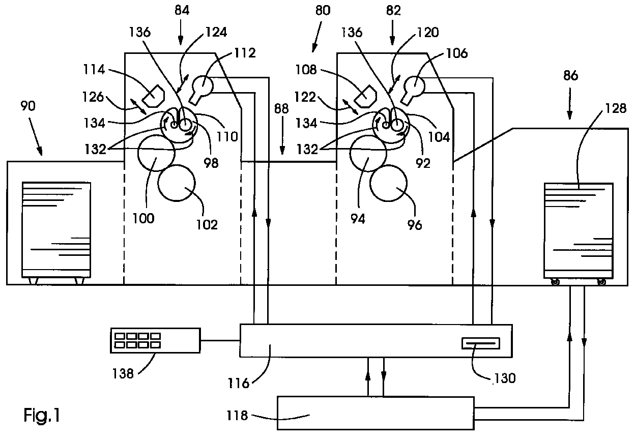
- the rotary printing machine shown in Fig. 1 in a row with A device for carrying out the method according to the invention comprises a first one Printing unit 82, a second printing unit 84, a sheet feeder 86, one Sheet transfer and / or sheet turning device 88, a sheet delivery 90 and a central control device 118 for controlling the said Components of the printing press including those not shown in FIG. 1 Drives of the components and of the printing units 82, 84, not shown assigned ink or ink and dampening units.
- Each of the printing units 82, 84 includes an impression cylinder 96, 102, a blanket cylinder 94, 100 and a printing form cylinder 92, 98 with a printing form 104, 110.
- the printing form 104, 110 are a cleaning device 108, 114 and one each Imaging device 106, 112 assigned.
- the imaging devices 106, 112 can be a laser, a modulator downstream of this and a die include modulated radiation to a focusing optics transmitting fiber optics.
- the Focusing optics can spiral over the surface of the printing form 104, 110 on the rotating printing form cylinders 92, 98 are guided, where the laser beam to the Positions of the grid drills the desired cells.
- the Imaging devices 106, 112 are by a Imaging control device 116 controlled, which is in a first operating mode the first imaging device 106 and in a second operating mode controls second imaging device 112 and that with the central Control device 118 is connected.
- the central control device 118 is connected to a control panel 138, via which in a known manner Operating parameters and commands for controlling the printing press can be entered.
- a control panel 138 Through which in a known manner Operating parameters and commands for controlling the printing press can be entered.
- Imaging control device 116 or an imaging control by the central control device 118 are also possible.
- the printing form cylinders 92, 98 are in an imaging position movable, in which they do not contact the blanket cylinders 94, 100.
- a Positioning 120, 124 of the imaging devices 106, 112 can additionally be provided so that in this way a suitable distance for imaging between the effective elements of the imaging devices 106, 112, e.g. B. Laser diodes or focusing optics, and the printing form surface of the Printing forms 104, 110 can be set and kept constant, so that a exactly defined diameter of the grid points or cells is guaranteed.
- the Cleaning devices 108, 114 are also positionable and can be in shape of a winding and unwinding cleaning cloth in combination with one the pressing element pressing the printing plate surface may be formed, wherein a cleaning fluid indirectly via the cleaning device or directly can be applied to the printing form surface.
- the implementation of the method according to the invention is exemplified below explained in the event that two print jobs are processed.
- the first Print job is already using the second printing unit 84 illustrated second printing form 110 printed.
- Sheets 128 are from Sheet feeder 86 to the first printing unit 82, from this via the Sheet transfer device 88 to the second printing unit 84 and via this to Supported sheet delivery 90.
- the first printing form 104 is imaged in the first Printing unit 82 for the second print job, which is the first print job to be processed below.
- the printing form cylinder 92 is switched off from the blanket cylinder 94, the Blanket cylinder 94 placed on the impression cylinder 96 or by this can be turned off.
- Processing the complete edition of the first Print job can be a sufficient for imaging the first printing form 104 Require a period of time so that complete imaging, including one Burning all pixels into the first printing form 104 and one subsequent cleaning of the first printing form 104 from the ablative Imaging of thermally decomposed printing plate material using the Cleaning device 108 can be carried out in this period.
- the second Print job started by the printing form cylinder 92 in a working position is brought, in which an interaction with the blanket cylinder 94th is given and by simultaneously the printing form cylinder 98 from such Working position is brought into an imaging position.
- Such a flying one Changing the printing form minimizes the amount of waste, with a possibly briefly washing the blanket cylinder 100 and / or picking it up whose contact to the impression cylinder 102 can take place.
- the preferably as Printing film webs 104, 110 formed by printing foils can be formed by a Printing film feed 132 can be renewed by illustrated and used Areas of a printing film web wound onto a first roll 134 and fresh ones imageable printing film sections unwound from a second roll 136 become. After that, while printing the second print job The second printing form 110 is imaged in the first printing unit 82.
- the imaging controller 116 can be operated manually or, as shown, by the central control device 118 optionally in a first operating mode - for Activation of the first imaging device 106 for imaging the first Printing form 104 - and in a second operating mode - for controlling the second Imaging device 112 for imaging the second printing form 110 - switchable be.
- the print image data and other data for imaging the printing forms 104, 110 can be from the imaging control device 116 in the data flow upstream electronic publishing systems on-line or, as shown, by portable data storage media 130, e.g. B. floppy disks.
- the Connection of the imaging control device 116 to the central one Control device 118 and also an integration in the latter enable a further one Use of the image data for the control of further machine components, e.g.
- the printing press 80 for inking unit-specific setting, as well as a current operating status the printing press 80, in particular the printing units 82, 84 Signal flow to the imaging control device 116. Furthermore, one is also optional Connection of the imaging control device 116 to the Imaging devices 106, 112 and their activation and deactivation possible by manual operation.
- the printing press 80 in other functions also as a multi-color printing machine and as a beauty and Back printing machine operated, z. B. one after the other imaging of the printing forms 104, 110 can take place before the start of printing.
- the printing press 80 can comprise further printing units, which are the printing units 82, 84 can be upstream, intermediate and downstream.
- the invention Procedure using appropriate control software in one Microprocessor circuit comprising central control device 118 realized.
- An example of a program flow chart for such control software is shown in Fig. 2 and is referred to below as an example to Fig. 1 described.
- step 142 After starting the program in stage 140, which, for. B. with turning on Printing machine can take place, in step 142, the printing positions in second printing unit 84 set, z. B. the one already fully illustrated first Printing form cylinder 98 carrying printing form 110 from an imaging position in a working position is brought relative to the blanket cylinder 100.
- the next program stage 144 is the printing in the second printing unit 84 Printing machine 80 started.
- the imaging of the first takes place in a subsequent program stage 146
- Printing form 104 which is complete in a further program stage 148 is completed, so that the first printing form 104 is now ready for printing.
- an adjustment of the printing positions in the first printing unit 82 e.g. B.
- a program level 150 After a first print job with the one contained in the second printing unit 84 second printing form 110 was completed and after the complete edition of the program step 152, in which a flying change from printing with the second printing unit 84 to printing with the first printing unit 82, i.e. H. one with the printing end of the printing with the second printing form 110 simultaneous printing start of a second print job with the first printing form 104.
- This flying change can take place by z.
- the Blanket cylinder 94 first on the inked printing plate cylinder 92 and is subsequently turned on the impression cylinder 96, meanwhile simultaneously the blanket cylinder 100 from the impression cylinder 102 and the Printing form cylinder 98 is turned off.
- the printing form cylinders 92, 98 can over Couplings can be coupled to and from the drive of the printing press 80 Be uncoupled so that the respective non-printing form cylinder 92; 98 through another drive with a machine speed independent Imaging speed can be driven.
- the second printing form 110 is renewed, e.g. B. by manually replacing a printing form sleeve or a printing plate is automatically changed or a print film web that can be wound up and unwound is clocked further, so that the printing form cylinder 98 with a new imageable Printing form 110 is provided.
- a further program stage 156 there is a Return query, that is, whether the second print job has other print jobs follow or whether the number n of successive orders to be processed is greater than that Number z orders completed.
- one in FIG. 3 comprises Rotary printing machine shown a satellite printing unit 2 with four or more grouped around a multi-size common impression cylinder 14 Printing devices 6, 8, 10, 12 and an impression unit 4 with a first Impression device 16 and a second impression device 18 and if necessary, further impression facilities.
- the satellite printing unit 2 and the impression unit 4 can be coupled and uncoupled from one another, the Interface 48 of the coupling between the single-sized, second Transfer drum 26 and the double-sized - d. H. two sheets at the same time leading - transfer drum 24, which is a single-sized, first transfer drum 22 is upstream, runs.
- the satellite printing unit 2 and the Imprinting unit 4 can be coupled to one another with the connecting element 78, wherein further couplings are not shown in the figure.
- the driving Coupling can e.g. B. via an electronic coupling of separate drives both Units 2, 4 by means of the central control device 71 or via one into a of units 2; 4 integrated central drive and one of its drive power for other unit 2; 4 transmitting gear, z. B. realized a gear train be.
- At least one of the units 2; 4 is displaceable in a direction 46, while the other unit 2; 4 can be anchored stationary in the foundation 33.
- the Displaceability of the units 2, 4 can be guided in rails 35 Rollers 36 or other guides facilitating displacements can be made possible, the displaceable units 2, 4 in the foundation 33 with locking elements 37 can be locked.
- the units 2, 4 and operation with additional modules e.g. B. bow-laying and -interpreting and print processing modules, - d. H. an operational one optional combination and also separate operation of units 2, 4 - possible.
- the satellite printing unit 2 can essentially with a similar or mirror image trained additional satellite printing unit be combined so that a two-sided four or multi-color printing or a single-sided axis or multi-color printing is possible.
- the method according to the invention can be within only one of the satellite printing units or impression units or be carried out across modules.
- the transfer drums 22, 26 and the transfer drum 24 have printed sheets holding facilities, e.g. B. gripper bars and suction pads, so that the Print sheets 30 secure on the circumferential surfaces of the drum 22, 24, 26th guided and by a drum 22; 24 to the other drum 24; 26 handed over can be.
- the print sheet transfer device 22, 24, 26 can be switched and thereby be designed to be operable in two operating modes.
- the of the Sheet transfer device 22, 24, 26 from the satellite printing unit 2, z. B. directly from the quadruple-sized impression cylinder 14, a print image of the front side 40 carrying printing sheets 30 can in a first Operating mode - the straight printing mode - such to the impression unit 4, z. B.
- the sheet transfer device 22, 24, 26 operates as one Turning device, wherein the transfer drum 24 as a storage drum with the second transfer drum 26 in which acts here as a turning drum cooperates in a known manner, acts so that the printing sheets 30 applied the impression unit 4 are transferred, the printing sheets 30 with their previous front 40 rest on the impression cylinder 20 and a Printing the back 44 is feasible.
- the arrowheads in Fig. 3 symbolize the colors printed on the printed sheet on the respective page.
- a first variant includes that an illustration of one or more impression devices 16, 18 of the unit 4 during printing with the printing devices 5, 7, 9, 11 of the unit 2 or that during printing with one or more of the Impression devices 16, 18 of unit 4 illustrate one or more Printing devices 5, 7, 9, 11 of the unit 2 takes place.
- This first variant is too applicable to two coupled satellite printing units.
- one or more of the printing forms 5, 7, 9, 11 during printing with one or more of the printing forms 5, 7, 9, 11 illustrated can be used in separate operation of the Satellite printing unit 2 as well as with other modules, eg. B. the Impression unit 4, coupled operation can be realized.
- the preferred third variant includes the implementation of the invention Method by means of the devices 62 integrated in the impression unit 4, 70, 72, 73.
- the z. B. trained as a write head with laser diodes Imaging device 72 is in a first position a for imaging the first Printing form 49 and in a second position b for imaging the second Printing form 51 and optionally in a neutral position c. This can preferably done by pivoting the imaging device 72. In addition to the pivoting movement 74, a further one - if appropriate with this forcibly synchronized movement 76 of the imaging device 72 respectively.
- Imaging device 66, 72 a separate imaging control device 73 assigned. It can also be provided that the imaging devices 66, 72 a common, optionally switchable imaging control device 73 is assigned, which the imaging of the printing plates 5, 7, 9, 11 and Illustration of the printing forms 49, 51 controls.
- a single imaging device 66 with an associated one Imaging control device 73 for sequential imaging of the Printing devices 6, 8, 10, 12 or printing forms 5, 7, 9, 11 are used.
- Fig. 3 it is shown that the impression device 16 except for imaging Operation has taken place, for which the printing form cylinder 58 and the inking unit 60 Printing form cylinder 58 and the blanket cylinder 56 and the blanket cylinder 56 and impression cylinder 20 are separated and parked. While four-color printed images of a first printed in the satellite printing unit 2 Partial order on the front side 42 of the printing sheet with the second printing form 51 18 impression images are printed in the second impression device, one takes place Illustration of the first printing form 49 of the first impression device 16 for the Imprinting another imprint image into four-color print images of a second one Partial order.
- Printing form 49 can illustrate the second printing form 51 for a third Partial order take place, the printing form 51 brought first by a new one imageable printing form is replaced, then irradiation with the Imaging device 62 and this one may be required Cleaning the printing form 51 can be done with the cleaning device 62.
Landscapes
- Engineering & Computer Science (AREA)
- Mechanical Engineering (AREA)
- Inking, Control Or Cleaning Of Printing Machines (AREA)
- Rotary Presses (AREA)
- Manufacture Or Reproduction Of Printing Formes (AREA)
Abstract
Die Erfindung bezieht sich auf ein Verfahren zum Betrieb einer
Rotationsdruckmaschine (80), wobei während des Druckens mit einer ersten
Druckform (104) eine zweite Druckform (110) bebildert wird. Weiterhin bezieht sich
die Erfindung auf eine Vorrichtung zur Durchführung des Verfahrens, welche
mindestens eine den Druckformen (104, 110) zugeordnete
Bebilderungseinrichtung (106, 108) umfaßt.
Description
Die Erfindung betrifft ein Verfahren zum Betrieb einer Rotationsdruckmaschine mit mindestens zwei in der Druckmaschine bebilderbaren Druckformen, mit denen nach einer einmaligen Bebilderung mehrere Drucke durchführbar sind, gemäß dem Oberbegriff von Anspruch 1, und eine Vorrichtung zur Durchführung des Verfahrens.The invention relates to a method for operating a rotary printing press at least two printing forms that can be imaged in the printing press, with which after a single illustration several prints can be carried out, according to Preamble of claim 1, and an apparatus for performing the method.
In der DE 195 12 420 A1 ist eine Mehrfarbendruckmaschine mit einer mehreren Druckformzylindern nacheinander zuordenbaren Bebilderungseinheit beschrieben. Auf diese Weise werden die Kosten im Vergleich zu einer Zuordnung von je einer Bebilderungseinrichtung pro Druckformzylinder reduziert. Ein Bebildern von Druckformen während des Betriebes der Druckmaschine ist hier nicht vorgesehen, so daß für jeden Auftragswechsel eine Betriebsunterbrechung notwendig ist. Der daraus resultierende Makulaturanfall bei Betriebsfortsetzung und die in der Summe hohen Stillstandszeiten verursachen eine vergleichsweise schlechte Wirtschaftlichkeit.DE 195 12 420 A1 describes a multi-color printing press with one Printing form cylinders described sequentially assignable imaging unit. This way the costs are compared to an assignment of one Imaging device per printing form cylinder reduced. An illustration of Printing forms during the operation of the printing press are not provided here, so that a business interruption is necessary for each order change. Of the resulting waste in the event of business continuation and the total high downtimes cause a comparatively bad one Economics.
In der DE-PS 28 44 418 ist eine Rollenrotationsdruckmaschine mit fliegendem Druckbildwechsel in einer Eindruckeinheit beschrieben, das heißt, daß beim Erreichen einer bestimmten Auflage mit einem ersten Eindruckbild das momentan druckende Druckwerk abgestellt und ein weiteres Druckwerk der Eindruckeinheit ohne Maschinenstillstand in Betrieb genommen wird. Während das weitere Druckwerk arbeitet, kann das abgestellte Druckwerk für den nächsten Eindruck vorbereitet werden. Ein Bebildern von Druckformen in der Druckmaschine ist hier nicht vorgesehen, so daß bei kleinen Auflagenhöhen pro Druckbild die Kosten für die Druckvorstufe, z. B. die photochemische Plattenkopie, einen vergleichsweisen großen Kostenanteil der Gesamtkosten darstellen. Eine Automatisierung des Druckplattenwechsels läßt sich nur mit einem erheblichen technischen Aufwand erreichen.In DE-PS 28 44 418 is a web-fed rotary printing press with flying Print image change described in an impression unit, that is, when Reaching a certain edition with a first impression of the moment printing printing unit turned off and another printing unit of the impression unit is put into operation without machine downtime. During the further Printing unit works, the parked printing unit can be used for the next impression to get prepared. An illustration of printing forms in the printing press is here not provided, so that the cost of printing a small print run Prepress, e.g. B. the photochemical plate copy, a comparative represent a large proportion of the total costs. Automation of the Printing plate change can only be done with considerable technical effort to reach.
Der Erfindung liegt die Aufgabe zugrunde, ein Verfahren zum Betrieb einer Rotationsdruckmaschine, durch welches auch Teilauflagen geringer Auflagenhöhe bei geringem Makulaturanfall und günstiger Maschinenauslastung wirtschaftlich herstellbar sind, und eine Vorrichtung zur Durchführung des Verfahrens zu schaffen.The invention has for its object a method for operating a Rotary printing machine, through which partial runs of short runs are also possible economical with low waste and low machine utilization can be produced, and to provide a device for carrying out the method.
Die Aufgabe wird gemäß der Erfindung durch ein Verfahren mit den Merkmalen von Anspruch 1 und durch eine Vorrichtung mit den Merkmalen von Anspruch 5 oder 6 gelöst. Weitere Merkmale der Erfindung sind in den Unteransprüchen enthalten.The object is achieved according to the invention by a method with the features of Claim 1 and by a device with the features of claim 5 or 6 solved. Further features of the invention are contained in the subclaims.
Gemäß der vorliegenden Erfindung zeichnet sich das Verfahren zum Betrieb einer Rotationsdruckmaschine mit mindestens zwei in der Druckmaschine bebilderbaren Druckformen, mit denen nach einer einmaligen Bebilderung mehrere Drucke durchführbar sind, dadurch aus, daß während des Druckens mit der ersten Druckform die zweite Druckform bebildert wird. Die Bebilderung der zweiten Druckform erfolgt insbesondere für ein dem Drucken mit der ersten Druckform nachfolgendes Drucken mit der zweiten Druckform.According to the present invention, the method for operating a Rotary printing press with at least two images that can be imaged in the printing press Printing forms with which several prints after a single illustration are feasible, characterized in that during printing with the first Printing form the second printing form is illustrated. The illustration of the second Printing form takes place in particular for printing with the first printing form subsequent printing with the second printing form.
Erfindungsgemäß zeichnet sich eine Vorrichtung zur Durchführung des Verfahrens dadurch aus, daß der ersten Druckform eine erste Bebilderungseinrichtung und der zweiten Druckform eine zweite Bebilderungseinrichtung zugeordnet ist.According to the invention, an apparatus for performing the method is distinguished characterized in that the first printing form a first imaging device and the a second imaging device is assigned to a second printing form.
Erfindungsgemäß zeichnet sich eine weitere Vorrichtung zur Druckführung des Verfahrens dadurch aus, daß der ersten Druckform und der zweiten Druckform eine einzige gemeinsame Bebilderungseinrichtung zugeordnet ist, welche zur Bebilderung der ersten und der zweiten Druckform einsetzbar ist. According to the invention, a further device for pressure control of the Process characterized in that the first printing form and the second printing form only common imaging device is assigned, which for Illustration of the first and the second printing form can be used.
Das Verfahren läßt sich beim Betrieb von Rollenrotations- und von Bogenrotationsdruckmaschinen anwenden. Die Vorrichtungen sind in diesen Maschinen einsetzbar.The method can be used in the operation of rotary and rotary Use sheet-fed rotary printing machines. The devices are in these Machines can be used.
Im Gegensatz zu den dynamischen bzw. löschbaren Druckformen in als Ausgabegeräte für Personalcomputer genutzten, z. B. nach dem elektrografischen Prinzip arbeitende Druckern und Plottern, bezieht sich die Erfindung auf einmalig bebilderbare - also dem Master-System zuordenbare - Druckformen mit einem speicherbaren, nicht löschbaren Druckbild. Diese Druckformen können in Form einer Druckplatte, einer Hülse oder einer aushärtbaren Fluidschicht oder vorzugsweise einer ab- und aufwickelbaren Druckfolie auf Druckformzylindern aufgebracht sein. Die Druckformen können als Offsetdruckformen, z. B. als konventionelle Naßoffsetdruckformen oder als feuchtmittellos arbeitende Trockenoffsetdruckformen, und auch als Druckformen des direkten Flachdrucks (Dilitho) ausgebildet sein.In contrast to the dynamic or erasable forms in as Output devices used for personal computers, e.g. B. after the electrographic Principle working printers and plotters, the invention relates to unique imageable - i.e. assignable to the master system - printing forms with one storable, non-erasable print image. These printing forms can be in the form of a Pressure plate, a sleeve or a curable fluid layer or preferably a print film that can be unwound and wound up can be applied to printing form cylinders. The printing forms can be used as offset printing forms, e.g. B. as conventional Wet offset printing forms or as dry offset printing forms working without a dampening agent, and also be designed as printing forms of direct planographic printing (dilitho).
Die Direktbebilderung der Druckformen kann gemäß eines computer-to-press - Bebilderungsverfahrens erfolgen, welches eine örtliche bzw. pixelweise, vorzugsweise hochenergetische, Bestrahlung und eine nachfolgende manuelle oder automatische Reinigung der Druckform von Bebilderungsrückständen, z. B. thermisch zersetzen Materials einer nichtdruckenden Schicht der Druckform, umfaßt, so daß eine druckende Schicht an den Bildstellen freigelegt und aktiviert wird. Die nichtdruckende Schicht der Druckform kann eine Silikonschicht und die druckende Schicht eine Infrarotabsorptionsschicht sein.The direct imaging of the printing forms can be according to one computer-to-press - imaging process that uses a local or Pixel by pixel, preferably high-energy, radiation and a subsequent one manual or automatic cleaning of the printing form from Imaging residues, e.g. B. thermally decompose a non-printing material Layer of the printing form, so that a printing layer at the image points is exposed and activated. The non-printing layer of the printing form can be a Silicone layer and the printing layer an infrared absorption layer.
Die Reinigung der Druckform kann mittels einer Reinigungseinrichtung oder durch den Bedruckstoff erfolgen. Für die Reinigung kann der nachfolgend zu bedruckende oder aus einem speziell für die Reinigung vorgesehenen Material bestehender Bedruckstoff eingesetzt werden. Die Bebilderungsrückstände können vom Bedruckstoff unmittelbar während des Druckbeginns z. B. durch wenige dabei zu Makulatur werdende Bogen, oder in einem dem Drucken vorangehenden Reinigungsdurchlauf aufgenommen werden. Bei nichtablativen Bebilderungsverfahren ist ein dem eigentlichen Bebilderungsprozeß folgender Reinigungsprozeß nicht erforderlich. Statt dessen können sich andere Prozesse zum Druckfertigmachen der Druckform dem Bebildern anschließen.The printing form can be cleaned by means of a cleaning device or by the substrate. For cleaning, the one to be printed on below or made of a material specially designed for cleaning Printing material can be used. The imaging residues can be from Printing material immediately during the start of printing z. B. by a few Sheets becoming waste, or in a preceding sheet Cleaning run can be included. With non-ablative The imaging process is one that follows the actual imaging process Cleaning process not necessary. Instead, other processes can Make the printing form ready for printing and attach the images.
Die vollständige Bebilderung der Druckform erfordert in Abhängigkeit vom jeweiligen Bebilderungsverfahren einen bestimmten Zeitaufwand, z. B. insgesamt 12 Min., wobei die Bestrahlung der Druckform 6 Min. und das Reinigen 6 Min. dauern kann.The complete illustration of the printing form requires depending on the respective Imaging process a certain amount of time, z. B. a total of 12 minutes, the irradiation of the printing form and the cleaning can take 6 minutes.
Eine Gesamtauflage eines Druckproduktes kann aus einer ersten Teilauflage, welche mit einem Druckbild oder Eindruck versehen werden soll, und einer zweiten Teilauflage, welche mit einem anderen Druckbild oder Eindruckbild versehen werden soll, bestehen. Während der Herstellung der ersten Teilauflage unter Einsatz der das erste Druck- oder Eindruckbild druckenden ersten Druckform kann die zweite Druckform in der Druckmaschine bebildert, z. B. bestrahlt und gereinigt, werden. Erfordert die Herstellung der ersten Teilauflage einen sehr geringen Zeitaufwand, im obengenannten Beispiel weniger als 12 Min., ist es möglich, daß die Bebilderung der zweiten Druckform bei Fertigstellung der ersten Teilauflage noch nicht vollständig abgeschlossen ist, so daß die Druckmaschine für die Zeitdauer des Fertigbebilderns stillstehen kann. In diesem Fall erfolgt die Bebilderung der zweiten Druckform teilweise während des Druckens mit der ersten Druckform. In der Regel erfordert das Drucken der ersten Teilauflage jedoch weitaus mehr Zeit, als der Bebilderungsvorgang insgesamt in Anspruch nimmt, so daß dieser vollständig während des Druckens der ersten Teilauflage durchgeführt werden kann.A total print run can consist of a first partial print run, which is to be provided with a printed image or impression, and a second Partial edition, which are provided with a different print image or impression image should exist. During the production of the first partial edition using the The first printing form can print the first printing or impression image, the second Illustrated printing form in the printing press, e.g. B. irradiated and cleaned. The production of the first partial edition requires very little time, in example above less than 12 min., it is possible that the imaging of the second printing form is not yet complete when the first partial edition is completed is completed, so that the printing press for the duration of the finished imaging can stand still. In this case, the imaging of the second printing form takes place partially while printing with the first printing form. As a rule, this requires Printing the first partial edition, however, far more time than that Imaging process takes up so that it is complete can be carried out during the printing of the first partial edition.
In diesem Fall kann zwischen dem Drucken mit der ersten Druckform und dem Drucken mit der zweiten Druckform ein fliegender Wechsel erfolgen. Hierzu wird eine die zweite Druckform umfassende, zweite Druckeinrichtung über einen Antrieb auf Fortdruckdrehzahl beschleunigt, die zweite Druckeinrichtung mit der Druckmaschinendrehzahl synchronisiert und an den Hauptantrieb der Druckmaschine angekuppelt sowie die zweite Druckform in Druckposition gebracht. Währenddessen kann die erste Druckform aus der Druckposition gebracht und die die erste Druckform umfassende, erste Druckeinrichtung vom Hauptantrieb abgekuppelt werden, so daß die erste Druckeinrichtung bis zum Stillstand oder bis zum Erreichen einer geringeren Drehzahl (Schleichgang) verzögert werden kann. Der zuvor beschriebene fliegende Wechsel kann bei ununterbrochen fortlaufendem Betrieb einer dritten oder mehrerer weiterer von der Druckmaschine umfaßten Druckeinrichtungen oder Druckwerke erfolgen. Mit letztgenannten weiteren Druckwerken kann das eigentliche Druckbild der Gesamtauflage des Auftrages gedruckt werden, wobei mittels der als Eindruckeinheit fungierenden ersten und zweiten Druckeinrichtung zusätzliche Eindrucke in dieses eigentliche Druckbild gedruckt werden können. Die weiteren Druckwerke können dabei konventionelle Druckformen umfassen, die z. B. mittels Plattenkopie außerhalb der Druckmaschine und nicht innerhalb der Druckmaschine bebilderbar sind.In this case, you can choose between printing with the first printing form and the Print with the second printing form a flying change. For this, a the second printing form comprising second printing device via a drive Production speed accelerated, the second printing device with the Printing machine speed synchronized and to the main drive of the Coupled printing machine and brought the second printing form into printing position. Meanwhile, the first printing form can be brought out of the printing position and the the first printing form comprising the first printing device from the main drive be uncoupled so that the first printing device to a standstill or can be decelerated to reach a lower speed (creep speed). The flying change described above can be done continuously Operation of a third or more others included in the printing press Printing devices or printing units take place. With the latter others Printing units can be the actual print image of the total print run of the order are printed, the first and second printing device additional impressions in this actual print image can be printed. The other printing units can be conventional Include printing forms, the z. B. by means of plate copying outside the printing press and cannot be imaged within the printing press.
Bei Aufträgen mit mehr als zwei Teilauflagen kann eine wechselweise Bebilderung und ein wechselweiser Einsatz der ersten Druckform und der zweiten Druckform erfolgen. Selbstverständlich kann das Verfahren auch unter Verwendung von mehr als zwei in der Druckmaschine bebilderbaren Druckformen durchgeführt werden, wobei z. B. eine erste Druckform im Einsatz ist, während eine zweite Druckform und eine dritte Druckform bebildert werden. Nach Fertigstellung der mit der ersten Druckform gedruckten Teilauflage erfolgt ein Wechsel des Druckwerkes, so daß die folgenden Drucke oder Eindrucke unter Einsatz der zweiten Druckform durchgeführt werden, währenddessen die Bebilderung der ersten Druckform beginnt und die Bebilderung der dritten Druckform zu Ende geführt wird. Die erste und die zweite Bebilderungseinrichtung der Vorrichtung zur Durchführung des Verfahrens können durch je eine separat zugeordnete oder durch eine einzige wahlweise zuschaltbare gemeinsame elektronische Steuerungseinrichtung angesteuert werden. Die Steuerungseinrichtung kann z. B. einen Mikroprozessor enthalten und Bitmap-Dateien aus Electronic-Publishing-Systemen, z. B. aus einem Raster-Image-Processor, übernehmen, wobei diese digitalen Daten an die z. B. eine Zeile von 11 Laser-Dioden oder elektroerosive Funken erzeugende Elektroden umfassenden Schreibköpfe der Bebilderungseinrichtungen weitergeleitet werden. Eine gemeinsame Bebilderungseinrichtung der erfindungsgemäßen Vorrichtung kann durch ein wahlweises Anbringen, z. B. ein Umstecken von einer ersten, der ersten Druckform zugeordneten Halterung in eine zweite, der zweiten Druckform zugeordnete Halterung, der jeweiligen Druckform zugeordnet werden. Vorzugsweise kann die gemeinsame Bebilderungseinrichtung in eine ersten Position zur Bebilderung der ersten Druckform und in eine zweite Position zur Bebilderung der zweiten Druckform verstellbar, z. B. verschieb-, dreh- oder schwenkbar, ausgebildet sein. Weitere Zuordnungen oder Verstellungen der gemeinsamen Bebilderungseinrichtung in Positionen, z. B. in eine Bebilderungsposition zur Bebilderung einer dritten oder weiterer Druckformen oder in eine eine Reinigung der zweiten Druckform während des Einsatzes der ersten Druckform ermöglichende Neutralposition, sind möglich.In the case of orders with more than two partial runs, alternate images can be used and an alternate use of the first printing form and the second printing form respectively. Of course, the method can also be done using more are carried out as two printing forms that can be imaged in the printing press, where z. B. a first printing form is in use, while a second printing form and a third printing form can be illustrated. After completion of the first Printing form printed partial edition there is a change of the printing unit, so that the following prints or impressions carried out using the second printing form during which the imaging of the first printing form begins and the Illustration of the third printing form is completed. The first and the second Imaging device of the device for performing the method can by a separately assigned one or by a single selectable one common electronic control device can be controlled. The Control device can e.g. B. contain a microprocessor and bitmap files from electronic publishing systems, e.g. B. from a raster image processor, take over, these digital data to the z. B. a line of 11 Including laser diodes or electroerosive spark generating electrodes Print heads of the imaging devices are forwarded. A common imaging device of the device according to the invention can by optional attachment, e.g. B. a change of a first, the first Printing form associated holder in a second, the second printing form assigned bracket to be assigned to the respective printing form. Preferably can the common imaging device in a first position Imaging of the first printing form and in a second position for imaging the second printing form adjustable, e.g. B. displaceable, rotatable or pivotable be. Further assignments or adjustments of the common Imaging device in positions, e.g. B. in an imaging position Illustration of a third or further printing forms or in a cleaning of the second printing form during the use of the first printing form Neutral position are possible.
Eine Vorrichtung kann zur Durchführung einer besonderen Ausführungsform des erfindungsgemäßen Verfahrens, welches beinhaltet, daß in ein bereits gedrucktes Druckbild in-line Eindrucke eingedruckt werden, ausgebildet sein. Hierzu kann eine Rotationsdruckmaschine derart ausgestaltet sein, daß in Bedruckstofförderrichtung gesehen den für einen ein- oder zweiseitigen Vier- oder Mehrfarbendruck notwendigen Druckwerken zwei Eindruckeinrichtungen nachgeordnet sind. Jede der Eindruckeinrichtungen kann z. B. einen an einen Gegendruckzylinder an- und abstellbaren Druckformzylinder oder eine an den Gegendruckzylinder an- und abstellbare Druckform - und Gummituchzylinder-Kombination umfassen.A device can be used to carry out a special embodiment of the inventive method, which includes that in an already printed Print image can be printed in-line impressions, be trained. For this, a Rotary printing machine can be designed such that in the substrate conveying direction seen the one or two-sided four or multi-color printing necessary printing units are subordinated to two impression devices. Each of the Impression devices can e.g. B. on and on an impression cylinder adjustable printing form cylinder or one on the impression cylinder on and adjustable printing form and blanket cylinder combination.
Das erfindungsgemäße Verfahren umfaßt ferner eine Verfahrensvariante, bei welcher eine Druckmaschine mit vier Druckwerken für zweifarbiges Drucken eingesetzt wird, wobei jedes Druckwerk eine in der Druckmaschine bebilderbare Druckform umfaßt. Hierbei erfolgt während des Druckens eines ersten zweifarbigen Auftrages mit einem ersten und einem zweiten Druckwerk eine Bebilderung des dritten und vierten Druckwerkes für einen nachfolgenden zweiten zweifarbigen Auftrag. Auf diese Weise können Druckmaschinen mit einer großen Anzahl von Druckwerken für Aufträge mit einer kleineren Anzahl von zu verdruckenden Farben - z. B. Vierfarbendruckmaschinen für Zweifarbenaufträge oder Perfektordruckmaschinen mit acht Druckwerken und Wendeeinrichtung zum zweiseitigen Bedrucken in einem Druckgang für einseitige Vierfarbenaufträge - sehr wirtschaftlich ausgelastet werden.The method according to the invention further comprises a method variant, in which is a printing machine with four printing units for two-color printing is used, each printing unit being imageable in the printing press Printing form includes. This is done while printing a first two-color Order with a first and a second printing unit an illustration of the third and fourth printing units for a subsequent second two-tone Assignment. In this way, printing presses with a large number of Printing units for orders with a smaller number of colors to be printed - e.g. B. Four-color printing machines for two-color jobs or Perfector printing machines with eight printing units and turning device for two-sided printing in one print run for one-sided four-color jobs - very much be used economically.
Die Erfindung wird nachfolgend mit Bezug auf die Zeichnungen anhand bevorzugter Ausführungsformen beschrieben.The invention is more preferred below with reference to the drawings Embodiments described.
In den Zeichnungen zeigen:
- Fig. 1
- eine schematische Darstellung einer Rotationsdruckmaschine in Reihenbauweise mit einer Vorrichtung zur Durchführung des erfindungsgemäßen Verfahrens;
- Fig. 2
- ein Flußdiagramm, welches schematisch den Ablauf der Steuerungsvorgänge der Steuerung einzelner Maschinenkomponenten der in Fig. 1 dargestellten Druckmaschine bei der Durchführung des erfindungsgemäßen Verfahrens veranschaulicht und
- Fig. 3
- eine schematische Darstellung einer Rotationsdruckmaschine in Satellitenbauweise mit einer weiteren Vorrichtung zur Durchführung des erfindungsgemäßen Verfahren.
- Fig. 1
- is a schematic representation of a rotary printing press in series construction with a device for performing the method according to the invention;
- Fig. 2
- a flowchart which schematically illustrates the sequence of the control processes of the control of individual machine components of the printing press shown in Fig. 1 when performing the method according to the invention and
- Fig. 3
- a schematic representation of a rotary printing press in satellite design with a further device for performing the method according to the invention.
Die in Fig. 1 dargestellte Rotationsdruckmaschine in Reihenbauweise mit einer
Vorrichtung zur Durchführung des erfindungsgemäßen Verfahrens umfaßt ein erstes
Druckwerk 82, ein zweites Druckwerk 84, einen Bogenanleger 86, eine
Bogenübergabe- und/oder Bogenwendeeinrichtung 88, einen Bogenausleger 90 und
eine zentrale Steuerungseinrichtung 118 für die Steuerung der genannten
Komponenten der Druckmaschine einschließlich der in Fig. 1 nicht dargestellten
Antriebe der Komponenten sowie der nicht dargestellten, den Druckwerken 82, 84
zugeordneten Farb- oder Farb- und Feuchtwerke. Jedes der Druckwerke 82, 84
umfaßt einen Gegendruckzylinder 96, 102, einen Gummituchzylinder 94, 100 und
einen Druckformzylinder 92, 98 mit einer Druckform 104, 110. Den Druckformen 104,
110 sind je eine Reinigungseinrichtung 108, 114 und eine
Bebilderungseinrichtung 106, 112 zugeordnet. Die Bebilderungseinrichtungen 106,
112 können einen Laser, einen diesem nachgeordneten Modulator sowie eine die
modulierte Strahlung zu einer Fokusieroptik übertragende Faseroptik umfassen. Die
Fokusieroptik kann spiralförmig über die Oberfläche der Druckform 104, 110 auf dem
rotierenden Druckformzylinder 92, 98 geführt werden, wo der Laserstrahl an den
Positionen des Rasters die gewünschten Näpfchen bohrt. Die
Bebilderungseinrichtungen 106, 112 werden durch eine
Bebilderungssteuereinrichtung 116 gesteuert, welche in einem ersten Betriebsmodus
die erste Bebilderungseinrichtung 106 und in einem zweiten Betriebsmodus die
zweite Bebilderungseinrichtung 112 ansteuert und die mit der zentralen
Steuerungseinrichtung 118 verbunden ist. Die zentrale Steuerungseinrichtung 118 ist
mit einem Bedienpult 138 verbunden, über welches in bekannter Weise
Betriebsparameter und Befehle zur Steuerung der Druckmaschine eingebbar sind.
Eine von der zentralen Steuereinrichtung 118 getrennte
Bebilderungssteuereinrichtung 116 oder eine Bebilderungssteuerung durch die
zentrale Steuereinrichtung 118 sind ebenso möglich.The rotary printing machine shown in Fig. 1 in a row with
A device for carrying out the method according to the invention comprises a first one
Zur Bebilderung sind die Druckformzylinder 92, 98 in eine Bebilderungsposition
bewegbar, in der sie die Gummituchzylindern 94, 100 nicht kontaktieren. Eine
Positionierung 120, 124 der Bebilderungseinrichtungen 106, 112 kann zusätzlich
vorgesehen sein, so daß auf diese Weise ein für die Bebilderung geeigneter Abstand
zwischen den wirksamen Elementen der Bebilderungseinrichtungen 106, 112, z. B.
Laser-Dioden oder einer Fokusieroptik, und der Druckformoberfläche der
Druckformen 104, 110 eingestellt und konstant gehalten werden kann, so daß ein
exakt definierter Durchmesser der Rasterpunkte bzw. Näpfchen gewährleistet ist. Die
Reinigungseinrichtungen 108, 114 sind ebenfalls positionierbar und können in Form
eines auf- und abwickelbaren Reinigungstuches in Kombination mit einem dieses an
die Druckformoberfläche anpressenden Andrückelement ausgebildet sein, wobei
indirekt über die Reinigungseinrichtung oder auf direktem Weg ein Reinigungsfluid
auf die Druckformoberfläche aufgebracht werden kann.For the purpose of imaging, the
Die Durchführung des erfindungsgemäßen Verfahrens wird nachfolgend beispielhaft
für den Fall erläutert, daß zwei Druckaufträge bearbeitet werden. Der erste
Druckauftrag wird mit dem zweiten Druckwerk 84 unter Einsatz der bereits
bebilderten zweiten Druckform 110 gedruckt. Die Bögen 128 werden vom
Bogenanleger 86 zum ersten Druckwerk 82, von diesem über die
Bogenübergabeeinrichtung 88 zum zweiten Druckwerk 84 und über dieses zum
Bogenausleger 90 gefördert. Während die Bögen 128 im zweiten Druckwerk 84
bedruckt werden, erfolgt eine Bebilderung der ersten Druckform 104 im ersten
Druckwerk 82 für den zweiten Druckauftrag, welcher dem ersten Druckauftrag
nachfolgend bearbeitet werden soll. Bei der Bebilderung der ersten Druckform 104
ist der Druckformzylinder 92 vom Gummituchzylinder 94 abgestellt, wobei der
Gummituchzylinder 94 an den Gegendruckzylinder 96 angestellt oder von diesem
abgestellt sein kann. Die Bearbeitung der kompletten Auflage des ersten
Druckauftrages kann eine zur Bebilderung der ersten Druckform 104 hinreichende
Zeitspanne erfordern, so daß eine komplette Bebilderung, einschließlich eines
Einbrennens aller Bildpunkte bzw. Pixel in die ersten Druckform 104 sowie eines
nachfolgenden Reinigens der ersten Druckform 104 vom bei der ablativen
Bebilderung thermisch zersetzten Druckformmaterial mittels der
Reinigungseinrichtung 108, in dieser Zeitspanne durchführbar sein kann. Nach
Bearbeitung des ersten Druckauftrages wird die Bearbeitung des zweiten
Druckauftrages begonnen, indem der Druckformzylinder 92 in eine Arbeitsposition
gebracht wird, in welcher ein Zusammenwirken mit dem Gummituchzylinder 94
gegeben ist und indem gleichzeitig der Druckformzylinder 98 aus einer derartigen
Arbeitsposition in eine Bebilderungsposition gebracht wird. Ein solcher fliegender
Druckformenwechsel minimiert die anfallende Makulatur, wobei gegebenenfalls ein
kurzes Zwischenwaschen des Gummituchzylinders 100 und / oder ein Aufheben
dessen Kontaktes zum Gegendruckzylinder 102 erfolgen kann. Die vorzugsweise als
Druckfolienbahnen ausgebildeten Druckform 104, 110 können durch einen
Druckfolienvorschub 132 erneuert werden, indem bebilderte und gebrauchte
Bereiche einer Druckfolienbahn auf einen ersten Wickel 134 aufgewickelt und frische
bebilderbare Druckfolienabschnitte von einem zweiten Wickel 136 abgewickelt
werden. Danach kann während der Druckbearbeitung des zweiten Druckauftrages
im ersten Druckwerk 82 eine Bebilderung der zweiten Druckform 110 erfolgen.The implementation of the method according to the invention is exemplified below
explained in the event that two print jobs are processed. The first
Print job is already using the
Die Bebilderungssteuereinrichtung 116 kann manuell oder, wie gezeigt, durch die
zentrale Steuereinrichtung 118 wahlweise in einen ersten Betriebsmodus - zur
Ansteuerung der ersten Bebilderungseinrichtung 106 zur Bebilderung der ersten
Druckform 104 - und in einen zweiten Betriebsmodus - zur Ansteuerung der zweiten
Bebilderungseinrichtung 112 zur Bebilderung der zweiten Druckform 110 - schaltbar
sein. Die Druckbilddaten und andere Daten für die Bebilderung der Druckformen
104, 110 können von der Bebilderungssteuereinrichtung 116 von im Datenfluß
vorgeordneten electronic-publishing-Systemen on-line oder, wie gezeigt, von
transportablen Datenspeichermedien 130, z. B. Disketten, übernommen werden. Die
Verbindung der Bebilderungssteuereinrichtung 116 mit der zentralen
Steuereinrichtung 118 und auch eine Integration in letzerer ermöglichen eine weitere
Nutzung der Bilddaten für die Steuerung weiterer Maschinenkomponenten, z. B. zur
druckbildspezifschen Farbwerkseinstellung, sowie einen aktuelle Betriebszustände
der Druckmaschine 80, insbesondere der Druckwerke 82, 84, betreffenden
Signalfluß zur Bebilderungssteuereinrichtung 116. Ferner ist auch eine wahlweise
Zuschaltung der Bebilderungssteuereinrichtung 116 zu den
Bebilderungseinrichtungen 106, 112 sowie deren Aktivierung und Deaktivierung
durch manuelle Bedienung möglich. Selbstverständlich kann die Druckmaschine 80
in weiteren Funktionen auch als eine Mehrfarbendruckmaschine und als eine Schön- und
Widerdruckmaschine betrieben werden, wobei z. B. eine nacheinander
erfolgende Bebilderung der Druckformen 104, 110 vor Druckbeginn erfolgen kann.
Die Druckmaschine 80 kann weitere Druckwerke umfassen, die den Druckwerken
82, 84 vor -, zwischen- und nachgeordnet sein können. The
Bei einer bevorzugten Ausführungsform der Erfindung wird das erfindungsgemäße
Verfahren unter Einsatz einer entsprechenden Steuerungssoftware in der eine
Microprozessor-Schaltung umfassenden zentralen Steuereinrichtung 118 realisiert.
Ein Beispiel für einen Programmablaufplan für eine derartige Steuerungssoftware ist
in Fig. 2 dargestellt und wird nachfolgend beispielhaft auf Fig. 1 bezogen
beschrieben.In a preferred embodiment of the invention, the invention
Procedure using appropriate control software in one
Microprocessor circuit comprising
Nach dem Programmstart in Stufe 140, welcher z. B. mit dem Einschalten der
Druckmaschine erfolgen kann, werden in der Stufe 142 die Druckpositionen im
zweiten Druckwerk 84 eingestellt, wobei z. B. der eine bereits fertig bebilderte erste
Druckform 110 tragende Druckformzylinder 98 aus einer Bebilderungsposition in
eine Arbeitsposition relativ zum Gummituchzylinder 100 gebracht wird. In der
nächsten Programmstufe 144 wird mit dem Druck im zweiten Druckwerk 84 der
Druckmaschine 80 begonnen. Nach dem Druckbeginn mit dem zweiten Druckwerk
84 erfolgt in einer nachfolgenden Programmstufe 146 die Bebilderung der ersten
Druckform 104, welche in einer weiteren Programmstufe 148 vollständig
abgeschlossen wird, so daß jetzt die ersten Druckform 104 druckfertig bebildert ist.
Jetzt kann eine Einstellung der Druckpositionen im ersten Druckwerk 82, z. B. in
oben der beschriebenen Weise, gemäß einer Programmstufe 150 erfolgen.
Nachdem ein erster Druckauftrag mit der im zweiten Druckwerk 84 enthaltenen
zweiten Druckform 110 fertiggestellt wurde und nachdem die komplette Auflage des
ersten Druckauftrages gedruckt wurde, folgt eine Programmstufe 152, in welcher ein
fliegender Wechsel vom Drucken mit dem zweiten Druckwerk 84 zum Drucken mit
dem ersten Druckwerk 82, d. h. ein mit der Druckbeendung des Druckens mit der
zweiten Druckform 110 gleichzeitiger Druckbeginn eines zweiten Druckauftrages mit
der ersten Druckform 104. Dieser fliegende Wechsel kann erfolgen, indem z. B. der
Gummituchzylinder 94 zuerst an den eingefärbten Druckformzylinder 92 und
nachfolgend an den Gegendruckzylinder 96 angestellt wird, währenddessen
gleichzeitig der Gummituchzylinder 100 vom Gegendruckzylinder 102 und dem
Druckformzylinder 98 abgestellt wird. Die Druckformzylinder 92, 98 können über
Kupplungen an den Antrieb der Druckmaschine 80 koppelbar und von diesem
abkoppelbar sein, so daß der jeweils nichtdruckende Druckformzylinder 92; 98 durch
einen weiteren Antrieb mit einer von der Maschinengeschwindigkeit unabhängigen
Bebilderungsgeschwindigkeit antreibbar ist.After starting the program in
In einer nachfolgenden Programmstufe 154 wird die zweite Druckform 110 erneuert,
z. B. indem eine Druckformhülse manuell ausgetauscht wird oder eine Druckplatte
automatisch gewechselt wird oder eine auf- und abwickelbare Druckfolienbahn
weitergetaktet wird, so daß der Druckformzylinder 98 mit einer neuen bebilderbaren
Druckform 110 versehen wird. In einer weiteren Programmstufe 156 erfolgt eine
Rücksprungabfrage, das heißt, ob dem zweiten Druckauftrag weitere Druckaufträge
folgen bzw. ob die Anzahl n hintereinander zu bearbeitender Aufträge größer als die
Anzahl z fertiggestellter Aufträge ist. Liegt kein weiterer Druckauftrag vor, kann,
nachdem die komplette Auflage des zweiten Druckauftrages gedruckt wurde, in einer
folgenden Programmstufe 158, das Drucken mit der ersten Druckform 104 beendet
werden, indem der Druckformzylinder 92 vom Gummituchzylinder 96 abgestellt wird.
Liegen weitere Druckaufträge, z. B. ein dritter Druckauftrag, vor, dann werden die
vorangegangenen Programmstufen erneut durchlaufen, wie mit der Schleife 160
angedeutet. In der letzten Programmstufe 161 wird das Programm beendet.In a
Gemäß einer bevorzugten Ausführungsform der Erfindung umfaßt eine in Fig. 3
dargestellte Rotationsdruckmaschine eine Satellitendruckwerkseinheit 2 mit vier oder
mehr um einen mehrfachgroßen gemeinsamen Gegendruckzylinder 14 gruppierten
Druckeinrichtungen 6, 8, 10, 12 und einer Eindruckwerkseinheit 4 mit einer ersten
Eindruckeinrichtung 16 und einer zweiten Eindruckeinrichtung 18 und
gegebenenfalls weiterer Eindruckeinrichtungen. Die Satellitendruckwerkseinheit 2
und die Eindruckwerkseinheit 4 sind zueinander an- und abkoppelbar, wobei die
Trennstelle 48 der Koppelung zwischen der einfachgroßen, zweiten
Übergabetrommel 26 und der doppeltgroßen - d. h. zwei Druckbögen zugleich
führenden - Transfertrommel 24, welcher eine einfachgroße, erste Übergabetrommel
22 vorgeordnet ist, verläuft. Die Satellitendruckwerkseinheit 2 und die
Eindruckwerkseinheit 4 sind mit dem Verbindungselement 78 aneinander koppelbar,
wobei weitere Koppelungen nicht in der Figur dargestellt sind. Die antriebsmäßige
Koppelung kann z. B. über eine elektronische Koppelung separater Antriebe beider
Einheiten 2, 4 mittels der zentralen Steuerungseinrichtung 71 oder über einen in eine
der Einheiten 2; 4 integrierten Zentralantrieb und einen dessen Antriebsleistung zur
anderen Einheit 2; 4 übertragendes Getriebe, z. B. einen Zahnräderzug, realisiert
sein.According to a preferred embodiment of the invention, one in FIG. 3 comprises
Rotary printing machine shown a
Zumindest eine der Einheiten 2; 4 ist in eine Richtung 46 verschiebbar, während die
andere Einheit 2; 4 stationär im Fundament 33 verankert sein kann. Die
Verschiebbarkeit der Einheiten 2, 4 kann durch in Laufschienen 35 geführte
Rollen 36 oder andere Verschiebungen erleichternde Führungen ermöglicht sein,
wobei die verschiebbaren Einheiten 2, 4 im Fundament 33 mit Feststellelementen 37
arretierbar sein können.At least one of the
Durch die geschaffene Trenn- und Koppelbarkeit ist eine Koppelung der Einheiten 2,
4 und ein Betrieb mit weiteren Modulen, z. B. bogenanlegenden und
-auslegenden sowie druckweiterverarbeitenden Modulen, - d. h. eine einsatzbedingte
wahlweise Kombination und auch ein Separatbetrieb der Einheiten 2, 4 - möglich.
Beispielsweise kann die Satellitendruckwerkseinheit 2 mit einer im wesentlichen
gleichartig oder spiegelbildlich ausgebildeten weiteren Satellitendruckwerkseinheit
kombiniert werden, so daß ein zweiseitiger Vier- oder Mehrfarbendruck oder ein
einseitiger Ach- oder Mehrfarbendruck möglich ist. Das erfindungsgemäße Verfahren
kann dabei innerhalb nur einer der Satellitendruckwerke- bzw. Eindruckeinheiten
oder modulübergreifend durchgeführt werden.Due to the separability and connectivity created, the
Die Übergabetrommeln 22, 26 und die Transfertrommel 24 weisen Druckbögen
haltende Einrichtungen, z. B. Greiferleisten und Sauggreifer, auf, so daß die
Druckbögen 30 lagesicher auf den Umfangsoberflächen der Trommel 22, 24, 26
geführt und von einer Trommel 22; 24 zur anderen Trommel 24; 26 übergeben
werden können. Die Druckbogentransfereinrichtung 22, 24, 26 kann umstellbar und
dadurch in zwei Betriebsmodi betreibbar ausgebildet sein. Die von der
Bogentransfereinrichtung 22, 24, 26 von der Satellitendruckwerkseinheit 2, z. B.
direkt vom vierfachgroßen Gegendruckzylinder 14 übernommenen, ein Druckbild auf
der Vorderseite 40 tragenden Druckbögen 30 können in einem ersten
Betriebsmodus - dem Schöndruckmodus - derart an die Eindruckwerkseinheit 4, z.
B. direkt an den mehrfachgroßen Gegendruckzylinder 20, übergeben werden, daß
mit der Eindruckwerkseinheit 4 Eindruckbilder in das Druckbild der Vorderseite 42
eindruckbar sind. In einem zweiten Betriebsmodus - dem Schön- und
Wiederdruckmodus - arbeitet die Druckbogentransfereinrichtung 22, 24, 26 als eine
Wendeeinrichtung, wobei die Transfertrommel 24 als eine Speichertrommel, die mit
der hierbei als Wendetrommel fungierenden zweiten Übergabetrommel 26 in
bekannter Weise zusammenwirkt, fungiert, so daß die Druckbögen 30 gewendet an
die Eindruckwerkseinheit 4 übergeben werden, wobei die Druckbögen 30 mit ihrer
vormaligen Vorderseite 40 auf dem Gegendruckzylinder 20 aufliegen und ein
Bedrucken der Rückseite 44 durchführbar ist. Die Pfeilspitzen in Fig. 3 symbolisieren
die auf den Druckbogen auf der jeweilige Seite aufgedruckten Farben.The transfer drums 22, 26 and the
Das erfindungsgemäße Verfahren kann mit der in Fig. 3 dargestellten Vorrichtung
auf verschiedene Weise durchgeführt werden. Eine ersten Variante beinhaltet, daß
eine Bebilderung einer oder mehrerer Eindruckeinrichtungen 16, 18, der Einheit 4
während des Druckens mit den Druckeinrichtungen 5, 7, 9, 11 der Einheit 2 erfolgt
oder daß während des Druckens mit einer oder mehreren der
Eindruckeinrichtungen 16, 18 der Einheit 4 eine Bebilderung einer oder mehrerer
Druckeinrichtungen 5, 7, 9, 11 der Einheit 2 erfolgt. Diese ersten Variante ist auch
auf zwei gekoppelte Satellitendruckwerkseinheiten anwendbar.The method according to the invention can be performed with the device shown in FIG. 3
can be done in different ways. A first variant includes that
an illustration of one or
Gemäß einer zweiten Variante werden ein oder mehrere der Druckformen 5, 7, 9, 11
während des Druckens mit einer oder mehreren der Druckformen 5, 7, 9, 11
bebildert. Diese Variante kann sowohl im Separatbetrieb der
Satellitendruckwerkseinheit 2 als auch im mit anderen Modulen, z. B. der
Eindruckwerkseinheit 4, gekoppelten Betrieb realisiert sein. According to a second variant, one or more of the
Eine Kombination dieser Varianten untereinander und mit einer nachfolgend beschriebenen bevorzugten dritten Varianten und mit in der Beschreibung zu den Fig. 1 und 2 genannten oder in diesen gezeigten Merkmalen ist möglich.A combination of these variants with each other and with one below described preferred third variants and with in the description of the 1 and 2 or shown in these features is possible.
Die bevorzugte dritte Variante beinhaltet die Durchführung des erfindungsgemäßen
Verfahrens mittels der in die Eindruckwerkseinheit 4 integrierten Vorrichtungen 62,
70, 72, 73. Die z. B. als Schreibkopf mit Laserdioden ausgebildete
Bebilderungseinrichtung 72 ist in eine erste Position a zur Bebilderung der ersten
Druckform 49 und in eine zweite Position b zur Bebilderung der zweiten
Druckform 51 sowie gegebenenfalls in eine Neutralpositon c stellbar. Dies kann
vorzugsweise erfolgen, indem die Bebilderungseinrichtung 72 geschwenkt wird.
Neben der Schwenkbewegung 74 kann eine weitere - gegebenenfalls mit dieser
zwangsweise synchronisierte - Bewegung 76 der Bebilderungseinrichtung 72
erfolgen.The preferred third variant includes the implementation of the invention
Method by means of the
Bei der in Fig. 3 dargestellten Ausführungsvariante ist jeder
Bebilderungseinrichtung 66, 72 eine separate Bebilderungssteuereinrichtung 73
zugeordnet. Es kann auch vorgesehen sein, daß den Bebilderungseinrichtungen 66,
72 eine gemeinsame, wahlweise zuschaltbare Bebilderungssteuereinrichtung 73
zugeordnet ist, welche die Bebilderung der Druckformen 5, 7, 9, 11 und die
Bebilderung der Druckformen 49, 51 steuert.In the embodiment variant shown in FIG. 3, everyone is
Imaging
Ferner kann auch eine einzige Bebilderungseinrichtung 66 mit zugehöriger
Bebilderungssteuereinrichtung 73 zur nacheinander erfolgenden Bebilderung der
Druckeinrichtungen 6, 8, 10, 12 bzw. Druckformen 5, 7, 9, 11 eingesetzt werden.Furthermore, a
In Fig. 3 ist dargestellt, daß die Eindruckeinrichtung 16 zur Bebilderung außer
Betrieb genommen ist, wozu der Druckformzylinder 58 und das Farbwerk 60, der
Druckformzylinder 58 und der Gummituchzylinder 56 sowie der Gummituchzylinder
56 und Gegendruckzylinder 20 voneinander getrennt und abgestellt sind. Während
in der Satellitendruckwerkseinheit 2 gedruckte vierfarbige Druckbilder eines ersten
Teilauftrages auf der Vorderseite 42 des Druckbogens mit der zweiten Druckform 51
der zweiten Eindruckeinrichtung 18 Eindruckbilder eingedruckt werden, erfolgt eine
Bebilderung der ersten Druckform 49 der ersten Eindruckeinrichtung 16 für das
Eindrucken eines anderen Eindruckbildes in vierfarbige Druckbilder eines zweiten
Teilauftrages. Während des Druckens dieses zweiten Teilauftrages mit der ersten
Druckform 49 kann eine Bebilderung der zweiten Druckform 51 für einen dritten
Teilauftrag erfolgen, wobei zuerst die gebrachte Druckform 51 durch eine neue
bebilderbare Druckform ersetzt wird, dann eine Bestrahlung mit der
Bebilderungseinrichtung 62 und dieser nachfolgend eine eventuell erforderliche
Reinigung der Druckform 51 mit der Reinigungsvorrichtung 62 erfolgen kann. In Fig. 3 it is shown that the
- 22nd
- SatellitendruckwerkseinheitSatellite printing unit
- 44th
- EindruckwerkseinheitImpression unit
- 5, 7, 9, 115, 7, 9, 11
- DruckformenPrinting forms
- 6, 8, 10, 126, 8, 10, 12
- DruckeinrichtungPrinting device
- 14, 2014, 20
- GegendruckzylinderImpression cylinder
- 1616
- erste Eindruckeinrichtungfirst impression device
- 1818th
- zweite Eindruckeinrichtungsecond impression device
- 2222
- erste Übergabetrommelfirst transfer drum
- 2424th
- TransfertrommelTransfer drum
- 2626
- zweite Übergabetrommelsecond transfer drum
- 2828
- BogenanlegerSheet feeder
- 3030th
- DruckbogenPrinted sheet
- 3131
- AnlagestapelInvestment pile
- 3232
- BogenauslegerSheet boom
- 3333
- Fundamentfoundation
- 3434
- AuslagestapelDelivery pile
- 3636
- Rollenroll
- 3737
- FeststellelementLocking element
- 3838
- LaufschieneTrack
- 40, 4240, 42
- BogenvorderseiteSheet front
- 4444
- BogenrückseiteBack of sheet
- 4646
- Richtungdirection
- 4848
- TrennstelleSeparation point
- 4949
- erste Druckformfirst printing form
- 50, 5650, 56
- GummituchzylinderBlanket cylinder
- 5151
- zweite Druckformsecond printing form
- 52, 5852, 58
- DruckformzylinderPrinting form cylinder
- 54, 6054, 60
- Farbwerk Inking unit
- 6262
- ReinigungseinrichtungCleaning facility
- 6464
- ZustellbewegungDelivery movement
- 6868
- Achseaxis
- 7070
- SchwenkarmSwivel arm
- 7171
- Zentrale SteuereinrichtungCentral control facility
- 7272
- BebilderungseinrichtungImaging device
- 7373
- BebilderungssteuereinrichtungImaging control device
- 7474
- SchwenkbewegungSwivel motion
- 7676
- BewegungMove
- 7878
- VerbindungselementFastener
- 8080
- Bogenoffset-RotationsdruckmaschineSheetfed rotary press
- 8282
- erstes Druckwerkfirst printing unit
- 8484
- zweites Druckwerksecond printing unit
- 8686
- BogenanlegerSheet feeder
- 8888
- BogenübergabeeinrichtungSheet transfer device
- 9090
- BogenauslegerSheet boom
- 92, 9892, 98
- DruckformzylinderPrinting form cylinder
- 94, 10094, 100
- GummituchzylinderBlanket cylinder
- 96, 10296, 102
- GegendruckzylinderImpression cylinder
- 104104
- erste Druckformfirst printing form
- 106106
- erste Bebilderungseinrichtungfirst imaging device
- 108108
- erste Reinigungseinrichtungfirst cleaning device
- 110110
- zweite Druckformsecond printing form
- 112112
- zweite Bebilderungseinrichtungsecond imaging device
- 114114
- zweite Reinigungseinrichtungsecond cleaning device
- 116116
- BebilderungssteuereinrichtungImaging control device
- 118118
- zentrale Steuereinrichtungcentral control device
- 120, 124120, 124
- Positionierung der BebilderungseinrichtungPositioning of the imaging device
- 122, 126122, 126
- Positionierung der ReinigungseinrichtungPositioning of the cleaning device
- 128128
- DruckbogenPrinted sheet
- 130130
- Datenspeichermedium Data storage medium
- 132132
- DruckfolienvorschubPrinting film feed
- 134134
- erster Wickelfirst wrap
- 136136
- zweiter Wickelsecond wrap
- 138138
- Bedienpultcontrol panel
- 140, 142, 144,140, 142, 144,
- 146, 148, 150,146, 148, 150,
- 152, 154, 156,152, 154, 156,
- 158, 160, 161158, 160, 161
- ProgrammstufenProgram levels
- a, b, ca, b, c
- PositionenPositions
Claims (13)
dadurch gekennzeichnet,
daß die zweite Druckform (51, 110) während des Druckens mit der ersten Druckform (49, 104) bebildert wird.Method for operating a rotary printing press with at least two printing forms that can be imaged in the printing press and with which a number of prints can be carried out after a single imaging process.
characterized by
that the second printing form (51, 110) is imaged with the first printing form (49, 104) during printing.
dadurch gekennzeichnet,
daß zwischen dem Einsatz der ersten Druckform (49, 104) und der zweiten Druckform (51, 110) zum Drucken ein fliegender Wechsel der Druckformen (49, 51; 104;110) erfolgt.Method according to claim 1,
characterized by
that between the use of the first printing form (49, 104) and the second printing form (51, 110) for printing there is a flying change of the printing forms (49, 51; 104; 110).
dadurch gekennzeichnet,
daß die Bebilderung der Druckformen (49, 51; 104, 110) durch örtliche Bestrahlung erfolgt.Method according to one or more of the preceding claims,
characterized by
that the printing plates (49, 51; 104, 110) are imaged by local radiation.
dadurch gekennzeichnet,
daß die Druckformen (49, 51; 104, 110) nach der Bestrahlung durch einen Reinigungsvorgang von Bebilderungsrückständen gereinigt werden. Method according to claim 3,
characterized by
that the printing plates (49, 51; 104, 110) are cleaned after the irradiation by a cleaning process of imaging residues.
dadurch gekennzeichnet,
daß der ersten Druckform (104) eine erste Bebilderungseinrichtung (106) und der zweiten Druckform (110) eine zweite Bebilderungseinrichtung (112) zugeordnet ist.Device with at least two printing forms that can be imaged in a printing press, with which several prints can be carried out after a single imaging, for carrying out the method according to one or more of claims 1 to 4, in a rotary printing press,
characterized by
that the first printing form (104) is assigned a first imaging device (106) and the second printing form (110) is assigned a second imaging device (112).
dadurch gekennzeichnet,
daß der ersten Druckform (49) und der zweiten Druckform (51) eine einzige gemeinsame Bebilderungseinrichtung (72) zugeordnet ist.Device with at least two printing forms that can be imaged in a printing press, with which several prints can be carried out after a single imaging, for carrying out the method according to one or more of claims 1 to 4, in a rotary printing press,
characterized by
that the first printing form (49) and the second printing form (51) are assigned a single common imaging device (72).
dadurch gekennzeichnet,
daß die gemeinsame Bebilderungseinrichtung (72) zur Bebilderung der ersten Druckform (49) in eine erste Position a und zur Bebilderung der zweiten Druckform (51) in eine zweite Position b verstellbar ist.Apparatus according to claim 6,
characterized by
that the common imaging device (72) for imaging the first printing form (49) in a first position a and for imaging the second printing form (51) in a second position b is adjustable.
dadurch gekennzeichnet,
daß die gemeinsame Bebilderungseinrichtung (72) in die erste Position a und die zweite Position b schwenkbar ist. Device according to claim 7.
characterized by
that the common imaging device (72) can be pivoted into the first position a and the second position b.
dadurch gekennzeichnet,
daß die Rotationsdruckmaschine (80) als eine Mehrfarbenbogenoffsetdruckmaschine ausgebildet ist.Device according to one or more of claims 5 to 8,
characterized by
that the rotary printing press (80) is designed as a multi-color sheetfed offset printing press.
dadurch gekennzeichnet,
daß die erste Druckform (49) einer ersten Eindruckeinrichtung (16) und die zweite Druckform (51) einer zweiten Eindruckeinrichtung (18) zugehörig ist.Device according to one or more of claims 5 to 9.
characterized by
that the first printing form (49) is associated with a first impression device (16) and the second printing form (51) with a second impression device (18).
dadurch gekennzeichnet,
daß die Bebilderungseinrichtung (72, 106, 112) einen Laserschreibkopf umfaßt.Device according to one or more of claims 5 to 10.
characterized by
that the imaging device (72, 106, 112) comprises a laser writing head.
dadurch gekennzeichnet,
daß den Bebilderungseinrichtungen (106, 112) eine gemeinsame Bebilderungssteuereinrichtung (116) zugeordnet ist.Device according to claim 5,
characterized by
that the imaging devices (106, 112) are assigned a common imaging control device (116).
Applications Claiming Priority (2)
| Application Number | Priority Date | Filing Date | Title |
|---|---|---|---|
| DE19743770A DE19743770A1 (en) | 1997-10-02 | 1997-10-02 | Method for operating a rotary printing press and device for carrying out the method |
| DE19743770 | 1997-10-02 |
Publications (3)
| Publication Number | Publication Date |
|---|---|
| EP0906825A2 true EP0906825A2 (en) | 1999-04-07 |
| EP0906825A3 EP0906825A3 (en) | 1999-09-15 |
| EP0906825B1 EP0906825B1 (en) | 2002-11-20 |
Family
ID=7844517
Family Applications (1)
| Application Number | Title | Priority Date | Filing Date |
|---|---|---|---|
| EP98115978A Expired - Lifetime EP0906825B1 (en) | 1997-10-02 | 1998-08-25 | Method for operating a rotary press |
Country Status (5)
| Country | Link |
|---|---|
| US (1) | US6101944A (en) |
| EP (1) | EP0906825B1 (en) |
| JP (1) | JPH11157046A (en) |
| DE (2) | DE19743770A1 (en) |
| IL (1) | IL126108A0 (en) |
Cited By (4)
| Publication number | Priority date | Publication date | Assignee | Title |
|---|---|---|---|---|
| WO2002024454A1 (en) * | 2000-09-20 | 2002-03-28 | Koenig & Bauer Aktiengesellschaft | Printing unit |
| EP1193057A1 (en) * | 2000-09-28 | 2002-04-03 | Koenig & Bauer Aktiengesellschaft | Printing press with production of images on printing plates |
| EP1834769A3 (en) * | 2006-03-18 | 2010-10-20 | manroland AG | Sheet fed printing press |
| EP1834771A3 (en) * | 2006-03-14 | 2011-05-11 | manroland AG | Rotary printing press |
Families Citing this family (29)
| Publication number | Priority date | Publication date | Assignee | Title |
|---|---|---|---|---|
| DE59802466D1 (en) * | 1997-06-03 | 2002-01-24 | Kba Planeta Ag | METHOD AND DEVICE FOR DRIVING A PRINTING MACHINE WITH AN INTEGRATED IMAGE DEVICE |
| DE19812226B4 (en) * | 1998-03-20 | 2008-08-14 | Koenig & Bauer Aktiengesellschaft | Method and device for imaging |
| DE19859437A1 (en) * | 1998-12-22 | 2000-06-29 | Heidelberger Druckmasch Ag | Inking unit |
| DE19961605A1 (en) * | 1999-01-18 | 2000-07-20 | Heidelberger Druckmasch Ag | Printing press for multiple color printing has image transfer process which prepares print masters for subsequent application to transfer rollers while previous images are being printed |
| DE29908649U1 (en) | 1999-05-15 | 1999-08-05 | Sandhoo, Sarbjeet Singh, 67133 Maxdorf | Self-service device for individual sample design of products |
| DE10046466A1 (en) | 1999-10-15 | 2001-04-19 | Heidelberger Druckmasch Ag | Modular sheet printing machine, includes registration correction at supply unit transferring sheets to the second backing-pressure cylinder |
| DE10047394A1 (en) | 1999-10-15 | 2001-04-19 | Heidelberger Druckmasch Ag | Modular printing machine system satellite system of print cylinders and a second printer with one zone-less printing device for uniform dosage of ink |
| DE10047040A1 (en) | 1999-10-15 | 2001-04-19 | Heidelberger Druckmasch Ag | Modular printing machine includes additional non-impact printer permitting individual markings, which is allocated to sheet transport system of printing machine |
| DE19949751A1 (en) | 1999-10-15 | 2001-04-19 | Heidelberger Druckmasch Ag | Modular printing machine system for printing sheets |
| JP2001322250A (en) * | 2000-05-17 | 2001-11-20 | Komori Corp | Printing press and control method for the printing press |
| JP2001322254A (en) * | 2000-05-17 | 2001-11-20 | Komori Corp | Printing press and control method for the printing press |
| US6474231B1 (en) | 2000-07-26 | 2002-11-05 | Heidelberger Druckmaschinen Ag | Multi-color printing press with common blanket cylinder |
| DE10050097A1 (en) * | 2000-10-09 | 2002-06-20 | Roland Man Druckmasch | Rubber cylinder sleeve for offset printing machines |
| DE10155038B4 (en) * | 2000-12-04 | 2014-03-06 | Heidelberger Druckmaschinen Ag | Changeable imaging device for imaging of printing forms |
| DE10105926B4 (en) * | 2001-02-09 | 2005-06-16 | Koenig & Bauer Ag | Rotary press |
| US6796239B2 (en) * | 2001-03-22 | 2004-09-28 | Heidelberger Druckmaschinen Ag | Method and device for driving a printing press |
| DE10121827B4 (en) * | 2001-05-04 | 2005-12-22 | Man Roland Druckmaschinen Ag | Printing unit with reversible imaging and digital conversion |
| US6851368B2 (en) * | 2001-08-29 | 2005-02-08 | Heidelberger Druckmaschinen Ag | Rotary printing press having a switchable speed-change gear mechanism with plant gears |
| US7692802B2 (en) * | 2001-11-15 | 2010-04-06 | Heidelberger Druckmaschinen Ag | Image setting device, module and printing press for relative motion compensation of image setting device and printing form |
| US6722279B2 (en) * | 2001-12-05 | 2004-04-20 | Heidelberger Druckmaschinen Ag | Device and corresponding method for rapid image data transfer in printing presses |
| DE10308436C5 (en) * | 2003-02-27 | 2010-08-26 | Heidelberger Druckmaschinen Ag | Printing platesetter for recording artwork |
| DE10319685A1 (en) * | 2003-05-02 | 2004-11-18 | Werner Kammann Maschinenfabrik Gmbh | Device for exposing printing plates of a printing unit |
| DE102004021657B4 (en) * | 2004-05-03 | 2010-04-08 | Manroland Ag | Method for carrying out a printing plate-specific production change on a printing press |
| DE102005018367B4 (en) * | 2004-12-20 | 2008-08-07 | Koenig & Bauer Aktiengesellschaft | Apparatus for forming a printed image on at least one print image location on a form cylinder and their use |
| WO2006067117A1 (en) | 2004-12-20 | 2006-06-29 | Koenig & Bauer Aktiengesellschaft | Device for producing a printed image at at least one printed image location |
| US20070235923A1 (en) * | 2006-04-05 | 2007-10-11 | Keller James J | Sheet feeder, feed roller system and method |
| DE102006032201B4 (en) * | 2006-07-12 | 2013-07-18 | Koenig & Bauer Aktiengesellschaft | Handling device for handling printing plates in a printing machine |
| US7920279B2 (en) * | 2006-10-13 | 2011-04-05 | Infoprint Solutions Company, Llc | Apparatus and methods for improved printing in a tandem LED printhead engine |
| DE102010001314A1 (en) | 2010-01-28 | 2011-08-18 | KOENIG & BAUER Aktiengesellschaft, 97080 | Method for operating sheet-fed offset print machine, involves arranging multiple aggregates in series, forming printing elements, paint work or combination of printing element and paint work |
Family Cites Families (22)
| Publication number | Priority date | Publication date | Assignee | Title |
|---|---|---|---|---|
| DE7235379U (en) * | 1972-12-21 | H Clauberg Maschinenfab | Imprinting work | |
| DE1039537B (en) * | 1956-02-17 | 1958-09-25 | Goebel Gmbh Maschf | Method and device for printing alternating text or image impressions |
| DE2033836C3 (en) * | 1970-07-08 | 1980-07-10 | Walter Dr. 6100 Darmstadt Matuschke | Web-fed rotary printing press |
| DE2844418C3 (en) * | 1978-10-12 | 1982-02-11 | Albert-Frankenthal Ag, 6710 Frankenthal | Web-fed rotary printing machine with a device for producing printed products with changing impressions |
| DE3825145A1 (en) * | 1988-07-23 | 1990-01-25 | Koenig & Bauer Ag | ROLL ROTATION OFFSET PRINTING MACHINE WITH A PRINTER FOR FLYING PLATE REPLACEMENT |
| US5163368B1 (en) * | 1988-08-19 | 1999-08-24 | Presstek Inc | Printing apparatus with image error correction and ink regulation control |
| US5072671A (en) * | 1988-11-09 | 1991-12-17 | Man Roland Druckmaschinen Ag | System and method to apply a printing image on a printing machine cylinder in accordance with electronically furnished image information |
| DE3837898A1 (en) * | 1988-11-09 | 1990-06-13 | Roland Man Druckmasch | METHOD AND DEVICE FOR THE INTEGRATED PRINT FORM MANUFACTURING ON AN OFFSET PRINTING MACHINE |
| DE4103744C1 (en) * | 1991-02-07 | 1992-09-17 | Man Roland Druckmaschinen Ag, 6050 Offenbach, De | |
| DE4112925A1 (en) * | 1991-04-19 | 1992-10-22 | Frankenthal Ag Albert | PRINTING UNIT FOR A ROTATIONAL PRINTING MACHINE |
| DE9116212U1 (en) * | 1991-04-19 | 1992-04-02 | Albert-Frankenthal Ag, 6710 Frankenthal | Printing unit for a rotary printing press |
| US5305019A (en) * | 1992-03-02 | 1994-04-19 | Rockwell International Corporation | Imaging system for a printing press |
| US5351617A (en) * | 1992-07-20 | 1994-10-04 | Presstek, Inc. | Method for laser-discharge imaging a printing plate |
| DE4328058A1 (en) * | 1993-08-20 | 1995-02-23 | Roland Man Druckmasch | Printing machine with at least one exchangeable cylinder, in particular an exchangeable forme cylinder, or with an exchangeable printing form |
| US5816161A (en) * | 1994-07-22 | 1998-10-06 | Man Roland Druckmaschinen Ag | Erasable printing plate having a smooth pore free metallic surface |
| DE19503619A1 (en) * | 1995-02-03 | 1996-08-08 | Heidelberger Druckmasch Ag | Satellite sheet printing press units |
| DE19512420B4 (en) * | 1995-04-03 | 2005-01-27 | Koenig & Bauer Ag | Multi-color printing machine with printing plate illustration |
| DE19523378A1 (en) * | 1995-06-30 | 1997-01-02 | Koenig & Bauer Albert Ag | Sheet offset rotary printing machine |
| DE19533811A1 (en) * | 1995-09-13 | 1997-03-20 | Heidelberger Druckmasch Ag | Controlling illustration of printed form carrier for printing press |
| DE19602289A1 (en) * | 1996-01-23 | 1997-07-24 | Roland Man Druckmasch | High resolution print cylinder |
| DE19603663A1 (en) * | 1996-02-02 | 1997-08-07 | Roland Man Druckmasch | Printing unit for the flying printing plate change |
| JP3466867B2 (en) * | 1997-03-28 | 2003-11-17 | 大日本スクリーン製造株式会社 | Printing equipment |
-
1997
- 1997-10-02 DE DE19743770A patent/DE19743770A1/en not_active Withdrawn
-
1998
- 1998-08-25 DE DE59806339T patent/DE59806339D1/en not_active Expired - Lifetime
- 1998-08-25 EP EP98115978A patent/EP0906825B1/en not_active Expired - Lifetime
- 1998-09-07 IL IL12610898A patent/IL126108A0/en unknown
- 1998-10-02 JP JP10281524A patent/JPH11157046A/en active Pending
- 1998-10-02 US US09/165,605 patent/US6101944A/en not_active Expired - Fee Related
Cited By (6)
| Publication number | Priority date | Publication date | Assignee | Title |
|---|---|---|---|---|
| WO2002024454A1 (en) * | 2000-09-20 | 2002-03-28 | Koenig & Bauer Aktiengesellschaft | Printing unit |
| US6895857B2 (en) | 2000-09-20 | 2005-05-24 | Koenig & Bauer Aktiengesellschaft | Printing unit of a web-fed printing press with driven cylinder pairs |
| EP1361047A3 (en) * | 2000-09-20 | 2008-10-29 | Koenig & Bauer Aktiengesellschaft | Printing unit |
| EP1193057A1 (en) * | 2000-09-28 | 2002-04-03 | Koenig & Bauer Aktiengesellschaft | Printing press with production of images on printing plates |
| EP1834771A3 (en) * | 2006-03-14 | 2011-05-11 | manroland AG | Rotary printing press |
| EP1834769A3 (en) * | 2006-03-18 | 2010-10-20 | manroland AG | Sheet fed printing press |
Also Published As
| Publication number | Publication date |
|---|---|
| US6101944A (en) | 2000-08-15 |
| IL126108A0 (en) | 1999-05-09 |
| EP0906825B1 (en) | 2002-11-20 |
| DE59806339D1 (en) | 2003-01-02 |
| DE19743770A1 (en) | 1999-04-08 |
| JPH11157046A (en) | 1999-06-15 |
| EP0906825A3 (en) | 1999-09-15 |
Similar Documents
| Publication | Publication Date | Title |
|---|---|---|
| EP0906825B1 (en) | Method for operating a rotary press | |
| EP0834398B1 (en) | Drive for a sheet-fed offset press | |
| DE19739283C2 (en) | Method for achieving the production printing status in a web-fed rotary printing press | |
| DE69809000T2 (en) | Printing machine with interchangeable plate cylinders mounted on a carriage | |
| DE69402638T2 (en) | Printing plate cylinder with a device for automatically supplying printing plate material for use in a system for producing printing plates | |
| EP1170122B1 (en) | Device for imaging surfaces in printing machines | |
| EP2098368B1 (en) | Method for individualising the sides of a printed product | |
| EP1176008B1 (en) | Multi-colour printing machine with a common blanket cylinder | |
| EP0824070A1 (en) | Method and apparatus for producing printed products | |
| EP0925189A1 (en) | Multicolor sheet-fed printing press | |
| WO2009040178A1 (en) | Method for accelerating a rotary press | |
| DE2033836A1 (en) | Method for printing a newspaper with several partial editions and rotary printing press for carrying out the method | |
| DE19921628A1 (en) | Process for optimizing the amount of ink or emulsion used in an offset printing process | |
| EP1361047A2 (en) | Printing unit | |
| DE60225386T2 (en) | Apparatus and method for automatically changing plate cylinders in rotary printing machines | |
| DE60129633T2 (en) | Printing machine and control method of this printing press | |
| DE10311514B4 (en) | Method for operating an offset printing unit and offset printing unit | |
| EP1179425B1 (en) | Method for treating a reusable printing form or cylinder in a printing machine | |
| DE3011031C2 (en) | Sheet-fed rotary proofing offset printing machine | |
| DE4407642C1 (en) | Process for changing the speed of a printing press | |
| EP2022643A2 (en) | Development of print plates in offset printers | |
| DE102023107271A1 (en) | Method for operating a printing press and printing press | |
| EP1354700A2 (en) | Process for handling renewable imageable printing plates or cylinders in printing machines | |
| EP1638773A1 (en) | Method for operating an inking system | |
| WO2008095557A1 (en) | Method for the stripping and/or run-up of a rotary press |
Legal Events
| Date | Code | Title | Description |
|---|---|---|---|
| PUAI | Public reference made under article 153(3) epc to a published international application that has entered the european phase |
Free format text: ORIGINAL CODE: 0009012 |
|
| 17P | Request for examination filed |
Effective date: 19980825 |
|
| AK | Designated contracting states |
Kind code of ref document: A2 Designated state(s): BE CH DE FR GB IT LI NL |
|
| AX | Request for extension of the european patent |
Free format text: AL;LT;LV;MK;RO;SI |
|
| PUAL | Search report despatched |
Free format text: ORIGINAL CODE: 0009013 |
|
| AK | Designated contracting states |
Kind code of ref document: A3 Designated state(s): AT BE CH CY DE DK ES FI FR GB GR IE IT LI LU MC NL PT SE |
|
| AX | Request for extension of the european patent |
Free format text: AL;LT;LV;MK;RO;SI |
|
| AKX | Designation fees paid |
Free format text: BE CH DE FR GB IT LI NL |
|
| 17Q | First examination report despatched |
Effective date: 20000925 |
|
| RTI1 | Title (correction) |
Free format text: METHOD FOR OPERATING A ROTARY PRESS |
|
| GRAG | Despatch of communication of intention to grant |
Free format text: ORIGINAL CODE: EPIDOS AGRA |
|
| GRAG | Despatch of communication of intention to grant |
Free format text: ORIGINAL CODE: EPIDOS AGRA |
|
| GRAH | Despatch of communication of intention to grant a patent |
Free format text: ORIGINAL CODE: EPIDOS IGRA |
|
| GRAH | Despatch of communication of intention to grant a patent |
Free format text: ORIGINAL CODE: EPIDOS IGRA |
|
| GRAA | (expected) grant |
Free format text: ORIGINAL CODE: 0009210 |
|
| AK | Designated contracting states |
Kind code of ref document: B1 Designated state(s): BE CH DE FR GB IT LI NL |
|
| REG | Reference to a national code |
Ref country code: GB Ref legal event code: FG4D Free format text: NOT ENGLISH |
|
| REG | Reference to a national code |
Ref country code: CH Ref legal event code: EP |
|
| REF | Corresponds to: |
Ref document number: 59806339 Country of ref document: DE Date of ref document: 20030102 |
|
| GBT | Gb: translation of ep patent filed (gb section 77(6)(a)/1977) |
Effective date: 20030127 |
|
| ET | Fr: translation filed | ||
| PG25 | Lapsed in a contracting state [announced via postgrant information from national office to epo] |
Ref country code: GB Free format text: LAPSE BECAUSE OF NON-PAYMENT OF DUE FEES Effective date: 20030825 |
|
| PG25 | Lapsed in a contracting state [announced via postgrant information from national office to epo] |
Ref country code: LI Free format text: LAPSE BECAUSE OF NON-PAYMENT OF DUE FEES Effective date: 20030831 Ref country code: CH Free format text: LAPSE BECAUSE OF NON-PAYMENT OF DUE FEES Effective date: 20030831 Ref country code: BE Free format text: LAPSE BECAUSE OF NON-PAYMENT OF DUE FEES Effective date: 20030831 |
|
| PLBE | No opposition filed within time limit |
Free format text: ORIGINAL CODE: 0009261 |
|
| STAA | Information on the status of an ep patent application or granted ep patent |
Free format text: STATUS: NO OPPOSITION FILED WITHIN TIME LIMIT |
|
| 26N | No opposition filed |
Effective date: 20030821 |
|
| BERE | Be: lapsed |
Owner name: *HEIDELBERGER DRUCKMASCHINEN A.G. Effective date: 20030831 |
|
| PG25 | Lapsed in a contracting state [announced via postgrant information from national office to epo] |
Ref country code: NL Free format text: LAPSE BECAUSE OF NON-PAYMENT OF DUE FEES Effective date: 20040301 |
|
| GBPC | Gb: european patent ceased through non-payment of renewal fee | ||
| REG | Reference to a national code |
Ref country code: CH Ref legal event code: PL |
|
| PG25 | Lapsed in a contracting state [announced via postgrant information from national office to epo] |
Ref country code: FR Free format text: LAPSE BECAUSE OF NON-PAYMENT OF DUE FEES Effective date: 20040430 |
|
| NLV4 | Nl: lapsed or anulled due to non-payment of the annual fee |
Effective date: 20040301 |
|
| REG | Reference to a national code |
Ref country code: FR Ref legal event code: ST |
|
| PG25 | Lapsed in a contracting state [announced via postgrant information from national office to epo] |
Ref country code: IT Free format text: LAPSE BECAUSE OF NON-PAYMENT OF DUE FEES Effective date: 20050825 |
|
| PGFP | Annual fee paid to national office [announced via postgrant information from national office to epo] |
Ref country code: DE Payment date: 20100920 Year of fee payment: 13 |
|
| REG | Reference to a national code |
Ref country code: DE Ref legal event code: R119 Ref document number: 59806339 Country of ref document: DE Effective date: 20120301 |
|
| PG25 | Lapsed in a contracting state [announced via postgrant information from national office to epo] |
Ref country code: DE Free format text: LAPSE BECAUSE OF NON-PAYMENT OF DUE FEES Effective date: 20120301 |